

Dini Argeo 3590EKR Series, 3590EXP Series, 3590EXT Series, 3590 EBOX Series, CPWE Series Technical Manual
...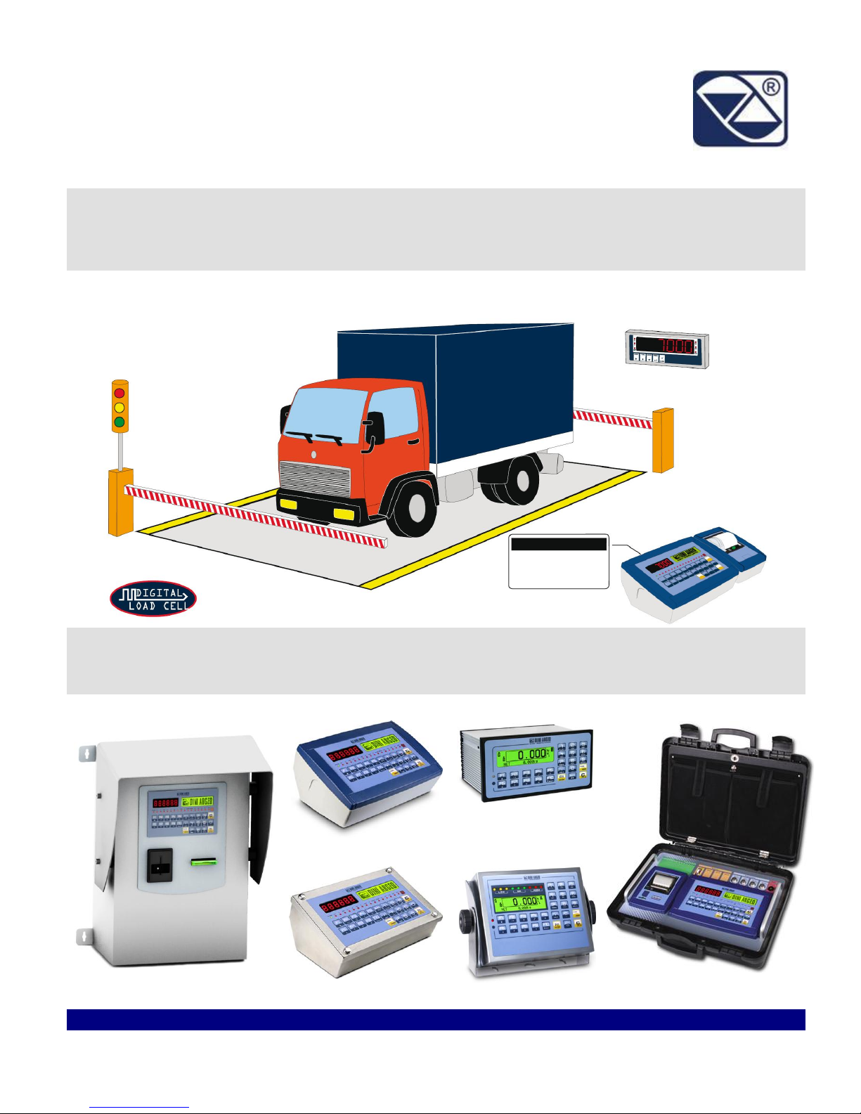
WEIGHT INDICATOR
TECHNICAL MANUAL
E-AF03: IN/OUT WEIGHING WITH
CUSTOMER/PRODUCT/VEHICLES DATABASE
3590EKR, 3590EXP, 3590EXT, 3590 EBOX, CPWE, CPWET
series indicator
E-AF03_05.01_14.07_EN_T

3590EKR, 3590EXP, 3590EXT, 3590 EBOX, CPWE, CPWET series indicator E-AF03_05.01_14.07_EN_T.doc
2
INDEX
1. REQUIREMENTS FOR AN OPTIMAL INSTALLATION ...................................................................................................................... 4
1.1 ELECTRICAL PRECAUTIONARY MEASURES ............................................................................................................................ 4
1.1.1 CABLE CLASSIFICATION ................................................................................................................................................. 5
1.1.2 RECOMMENDED DISTANCES AMONG CABLES ........................................................................................................... 5
1.1.3 MAXIMUM CABLE LENGTH .............................................................................................................................................. 5
1.2 EARTHING SYSTEM .................................................................................................................................................................... 6
2. CONNECTION TO THE LOAD RECEIVER .......................................................................................................................................... 9
2.1 ANOLOG LOAD CELLS ................................................................................................................................................................ 9
CONNECTION TO STANDARD “DINI ARGEO” FEMALE CONNECTOR ........................................................................................ 10
2.2 DIGITAL LOAD CELLS ................................................................................................................................................................ 10
2.3 CONNECTION OF LOAD CELLS TO INDICATOR ..................................................................................................................... 11
2.3.1 C16i DIGITAL CELL CONNECTION ............................................................................................................................... 12
2.3.2 RCD DIGITAL CELL CONNECTION ............................................................................................................................... 13
3. SETUP ENVIRONMENT ..................................................................................................................................................................... 14
3.1 SET-UP ENVIRONMENT BLOCK DIAGRAM ............................................................................................................................. 16
3.2 DESCRIPTION OF THE STEPS ................................................................................................................................................. 22
<< LAnG >> FIRMWARE LANGUAGE .................................................................................................................................... 22
<< nuM.SCA >> NUMBER OF CONNECTED SCALES (*)...................................................................................................... 22
<< F.ModE >> SCALE FUNCTIONING ................................................................................................................................... 23
<< SEtuP >> SCALE CONFIGURATION ................................................................................................................................. 32
<< diAG. >> DIAGNOSTICS MENU ......................................................................................................................................... 48
3.3 CALIBRATION OF THE SCALE .................................................................................................................................................. 52
3.3.1 CALIBRATION PROCEDURE.......................................................................................................................................... 52
3.3.2 LINEARIZATION POINTS ................................................................................................................................................ 54
3.3.3 ZONE OF USE DIFFERENT THAN THE ZONE OF CALIBRATION .............................................................................. 55
3.3.4 QUICK ZERO CALIBRATION .......................................................................................................................................... 55
3.3.5 CELL EQUALISATION PROCEDURE ............................................................................................................................. 56
3.3.6 ADJUSTMENT OF EQUALIZATION COEFFICIENT ....................................................................................................... 56
3.3.7 SETTING THE COMMUNICATION WITH DIGITAL CELLS ............................................................................................ 57
3.3.8 THEORETICAL CALIBRATION ....................................................................................................................................... 58
3.4 REMOTE SCALE CONFIGURATION ................................................................................................................................. 59
4. DISPLAY OF THE SCALE GRAVITY ACCELERATION AND CORRECTION OF THE WEIGHING ERROR DUE TO THE
DIFFERENT GRAVITY ATTRACTION BETWEEN THE CALIBRATION AND UTILISATION ZONE ................................................... 60
5. SERIAL OUTPUTS ............................................................................................................................................................................. 61
5.1 RS 485 CONNECTION ................................................................................................................................................................ 62
5.2 PC CONNECTION ....................................................................................................................................................................... 64
5.3 PRINTER CONNECTION ............................................................................................................................................................ 64
5.4 TRANSMISSION PROTOCOLS .................................................................................................................................................. 65
5.5 TRANSMISSION MODES ........................................................................................................................................................... 67
5.6 SERIAL COMMANDS FORMAT .................................................................................................................................................. 68
5.7 ADVANCED COMMANDS........................................................................................................................................................... 73
5.8 ALIBI MEMORY ........................................................................................................................................................................... 80
5.9 CUSTOMISATION OF THE STRING .......................................................................................................................................... 82
6. NETWORK MANAGEMENT ............................................................................................................................................................... 83
6.1 INSTRUMENT NETWORK CONFIGURATION ........................................................................................................................... 83
6.2 NETWORK FUNCTIONS............................................................................................................................................................. 84
7. SELF-SERVICE ................................................................................................................................................................................. 85
7.1 CONFIGURATION ....................................................................................................................................................................... 85
7.2 BADGE READER ....................................................................................................................................................................... 87
7.3 COIN BOX ................................................................................................................................................................................... 89
7.4 RFID READER ............................................................................................................................................................................ 91
8. ANALOGUE OUTPUT (OPTIONAL) .................................................................................................................................................. 97
8.1 OPERATING MODES ................................................................................................................................................................. 97
8.1.1 OUTPUT ON THE GROSS WEIGHT ............................................................................................................................... 97
8.1.2 OUTPUT ON THE NET WEIGHT ..................................................................................................................................... 98
8.2 CONFIGURATION ....................................................................................................................................................................... 99
9. PROGRAMMING THE PRINTOUTS ................................................................................................................................................ 100
9.1 PROGRAMMING EXAMPLE ..................................................................................................................................................... 102
9.2 ASCII CODE TABLES ............................................................................................................................................................... 103
9.2.1 CODE PAGE 1252 WINDOWS LATIN 1 ........................................................................................................................ 103

3590EKR, 3590EXP, 3590EXT, 3590 EBOX, CPWE, CPWET series indicator E-AF03_05.01_14.07_EN_T.doc
3
9.2.2 CODE PAGE 1251 WINDOWS CYRILLIC ..................................................................................................................... 104
9.2.3 CODE PAGE 1253 WINDOWS GREEK ........................................................................................................................ 105
9.3 LIST OF PRINT BLOCKS .......................................................................................................................................................... 106
9.3.1 ORDER BY KIND .......................................................................................................................................................... 106
9.3.2 NUMERICAL ORDER ................................................................................................................................................... 113
9.4 BLOCKS WITH PARAMETERS ................................................................................................................................................ 119
10. DISPLAY CUSTOMIZATION .......................................................................................................................................................... 127
11. ELECTRICAL SCHEMES ............................................................................................................................................................... 128
11.1 MOTHER BOARD ................................................................................................................................................................... 128
11.2 I/O EXPANSION BOARD (fitted with 3590EXT in IO version or CPWE) ................................................................................. 131
11.3 DISPLAY BOARD .................................................................................................................................................................... 132
11.4 CONTROL LIGHT .................................................................................................................................................................... 132

3590EKR, 3590EXP, 3590EXT, 3590 EBOX, CPWE, CPWET series indicator E-AF03_05.01_14.07_EN_T.doc
4
1. REQUIREMENTS FOR AN OPTIMAL INSTALLATION
To obtain the best results it is recommended to install the indicator and the platform (or transducer) in a place with the
following conditions:
A flat, level surface on which to rest
Stable and vibration free
No dust or strong vapours
No draughts
Make sure the platform is level or that the loading cells are resting evenly
Moderate temperature and humidity (15-30°C and 40-70%)
Do not install anywhere where there is the risk of explosion
All the indicator connections have to be made respecting the rules applicable in the zone and in the installing
environment. Respect the recommended electrical precautionary measures described in section 1.1.
Make sure that the grounding is made correctly, see section 1.2.
Everything not expressly described in this manual has to be considered as improper use of the equipment.
Avoid welding with load cells installed.
Use waterproof sheaths and couplings in order to protect the load cell cables.
Use a waterproof junction box to connect the cells.
1.1 ELECTRICAL PRECAUTIONARY MEASURES
Mains power supply is restricted to within ± 10% of the rated voltage
Electric protections (fuses etc.) are provided by the technician installing the instrument.
Respect the recommended minimal distances that are mentioned for the various cable categories, see sections
1.1.1 and 1.1.2.
The extension leads of the load cells or signal amplifiers, used for the connection of the serial ports and analogue
output must be within the allowed maximum lengths, see section 1.1.3.
The extension leads of the load cells or signal amplifiers must be screened. In addition they must be laid on their
own in a raceway or metal pipe as far away as possible from the power supply cables.
Install “RC” filters on the contactor coils, on the solenoid valves and on all devices producing electric
disturbances.
If it is possible that condensation could form inside the weight transmitter it is advisable to leave the instrument
powered at all times.
Every shielded cable or not (for instance PC cable, cell cable, power supply cable) connected to the indicator
should be as shorter as possible, then you have to come out of the shield the minimum length of cable, then
connect to the terminal box;
If the indicator is situated inside an electric panel, the power supply cable should be a shielded cable as shorter as
possible, distant from every coil supply cable, inverter, electromotive force, etc. and in addition dedicate an
uncoupler transformer in order to feed the indicator only.

3590EKR, 3590EXP, 3590EXT, 3590 EBOX, CPWE, CPWET series indicator E-AF03_05.01_14.07_EN_T.doc
5
1.1.1 CABLE CLASSIFICATION
The various cables are classified depending on the transmitted signals:
Category I
- Field bus, LAN (PROFIBUS, Ethernet, Devicenet…)
- Shielded data cables (RS232 …)
- Shielded cables for analogue/digital signals < 25V (sensors, load cells…)
- Low tension power supply cables (< 60V)
- Coaxial cables
Category II
- DC supply cables with tension > 60V and < 400V
- AC supply cables with tension > 25V and < 400V
Category III
- Power supply cables with tension > 400V
- Telephone cables
Category IV
- Any cable subject to lightning
1.1.2 RECOMMENDED DISTANCES AMONG CABLES
- When the cables are laid next to each other, these must be at the distances in the table below
- These distances are valid if in the air; these are reduced if the raceways are separated by grounded metallic shields.
- Different category cables can cross each other (90°)
Category I Category II Category III Category IV
≥ 100 mm
≥ 200 mm
≥ 500 mm
≥ 100 mm
≥ 500 mm
≥ 500 mm
1.1.3 MAXIMUM CABLE LENGTH
LOAD CELL CABLE
The maximum reachable length from the line using the appropriate load cell cable is:
- 50 m with cable 6 x 0,25 mm2
- 100 m with cable 6 x 0,5 mm
2
Over 100 metres is necessary to use a 6x1 mm2 cable
RS232 CABLE
The maximum reachable length from the line using the RS232 cable with a maximum baud rate of 19200, is about 15 m.
RS485 CABLE
The maximum reachable length from the line with the use of the appropriate cable for RS 485 connections (see section
5.1), is about 1200 meters.

3590EKR, 3590EXP, 3590EXT, 3590 EBOX, CPWE, CPWET series indicator E-AF03_05.01_14.07_EN_T.doc
6
ANALOG OUTPUT CABLE
The maximum length of the analogue output cable in current is:
- 100 m with cable 2 x 0,25 mm2
- 150 m with cable 2 x 0,5 mm2
- 300 m with cable 2 x 1 mm
2
The maximum length of the analogue output cable in voltage is:
- 50 m with cable 2 x 0,25 mm2
- 75 m with cable 2 x 0,5 mm2
- 150 m with cable 2 x 1 mm2
1.2 EARTHING SYSTEM
For the right earthing and the optimal functioning of the system, it is necessary to connect the indicator, the load cells, the
possible junction box and the weighing structure to the earth.
All earthing cables must have the shortest possible length in order to minimize their resistance.
INDICATOR
Connect the external earthing of the indicator to the earth through copper cables having at least a 16 mm2 cross-section.
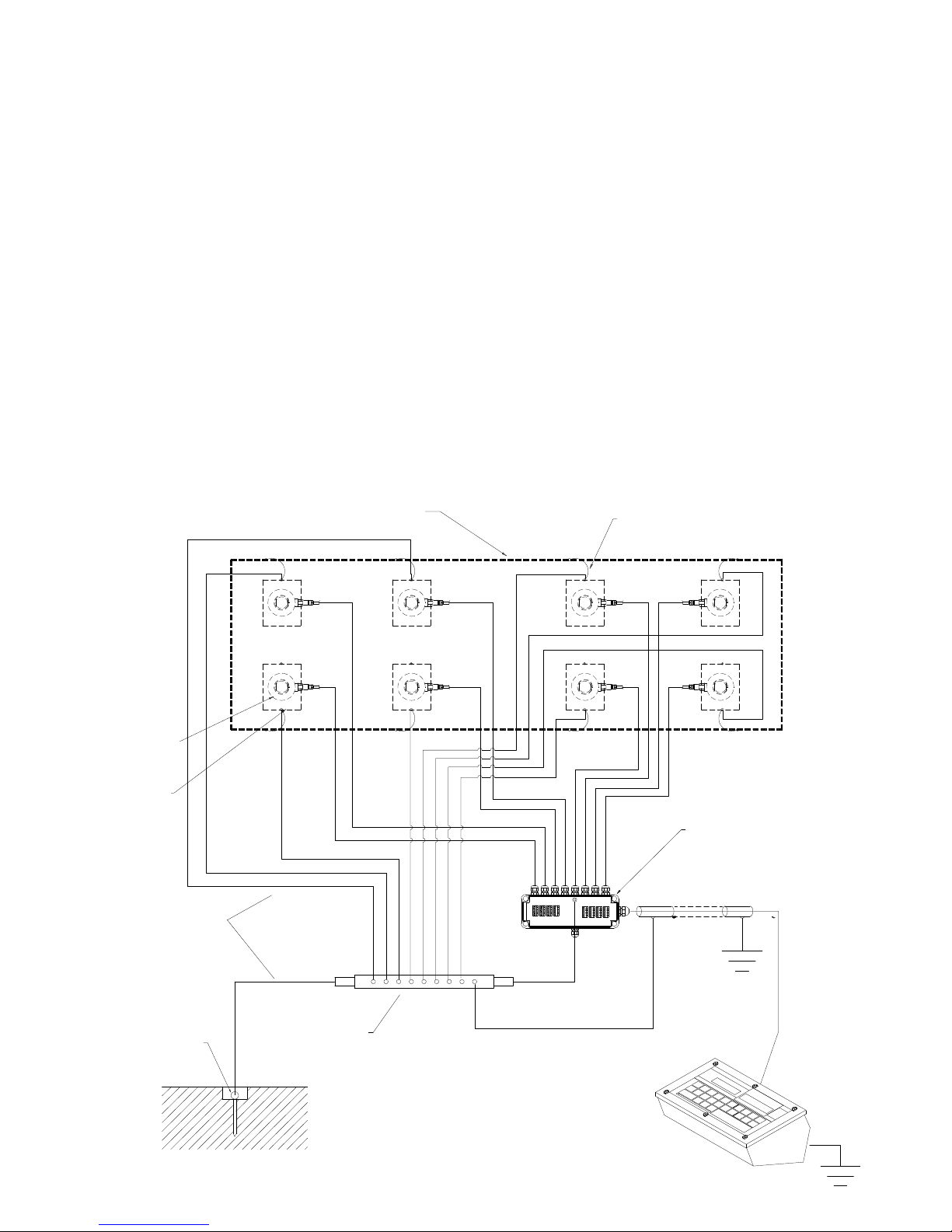
LOAD CELLS AND JUNCTION BOX
The earthing must be done by connecting the earthing cables to a ground bar with cables having a cross-section of at least
16 mm2 and by connecting the ground bar to a ground pole with a cable having a cross-section of at least 50 mm2.
- In the case the load cells are connected to the indicator through a junction box, it is necessary to connect the sheathing
both of cells cables and of indicator cable to the earthing of the junction box (refer to the junction box manual) and
connect this to the earth through copper cables having at least a 16 mm2 cross-section.
- If the load cells are connected directly to the indicator (without the use of the junction box), one should connect the
shieldings of the load cell cables to the grounding point (or earthing bar) inside the container.
- If the weighing system concerns large and/or outdoor structures, like weighbridges, and the junction box is connected
to the indicator in a distance that is greater than 10 m, or in the presence of noise, the cable shield must be earthed
both in the junction box and in the indicator, and the two ground leads must be connected with an earth cable having a
cross-section of at least 16 mm2.
WEIGHING STRUCTURE
Connect the weighing structure and the possible connected structures (for example silos that release material on the
weighing structure) to the earth through copper cables having at least a 16 mm2 cross-section.
Furthermore it is necessary that for each cell, one connects the upper part with the lower part of the load cell through a
copper braid section not less than 16 mm2; the upper part must be short-circuited with the surface of the weighing structure
and the lower part must be grounded through a copper braid section not less than 16 mm2.
CONNECTED SERIAL CABLES AND INSTRUMENTS
Connect the shield of the serial cable at the grounding point (or grounding bar) inside the container (on the end of the cable
toward the indicator) and at the earth connection of the connected instrument (on the end of the cable toward the indicator),
and ground the earth connection of the connected instrument, through a copper cable section not less than 16 mm2.
To avoid possible side effects, the earth references of the connection and power supply cable of the indicator and of the
connected instrument must be at the same potential.
3590EKR, 3590EXP, 3590EXT, 3590 EBOX, CPWE, CPWET series indicator E-AF03_05.01_14.07_EN_T.doc
7
GROUND POLE
POSITIONED UNDER
OR NEAR
WEIGHBRIDGE (NOT
SUPPLIED)
GENERAL NOTES:
All the grounding cables must have an adequate length, in order to obtain an overall resistance of grounding
system less than 1 Ω.
In the case the weighing system regards great and/or outdoor structures, like weighbridges:
- The grounding connection is to be made by connecting the grounding cables to a grounding bar and the
grounding bar to the grounding pole with a cable section not less than 50 mm2.
- the cable cross-section must be greater (for example 50 mm
2
instead of 16 mm2 and 100 mm2 instead of 50
mm2), because the voltage into play is greater (for example thunderbolts);
- the ground pole must be positioned at a distance of at least 10 metres from the weighbridge structure;
- one needs to open the SENSE inside the indicator in order to offset the drifts due to the increase in temperature.
One should check and remove, if necessary, the connection between the earth and the neutral wire of the electrical
installation.
EARTHING EXAMPLE WEIGHBRIDGE
LOAD CELL
PLATE
UNDER CELL
(NOT SUPPLIED)
JB8Q POSITIONED ON
THE WALL
SURROUNDING THE PIT
COPPER HOLED PLATE
ON THE SURROUNDING
WALL (NOT SUPPLIED)
U-BOLT BETWEEEN PLATE UNDER
CELL AND WEIGHBRIDGE
(NOT SUPPLIED)
WEIGHBRIDGE
Ø 8 (50 mm² section)
Ø 11,3 (100 mm² section)
EARTH CABLES
(NOT SUPPLIED)

3590EKR, 3590EXP, 3590EXT, 3590 EBOX, CPWE, CPWET series indicator E-AF03_05.01_14.07_EN_T.doc
8
EARTHING EXAMPLE OF A SILO
Non weighing
structure (silo)
Weighing
structure
Load cell
U-bolt between
plate under cell
and weighing
structure (not
supplied)
Ø 4,6 – 16 mm²
earth cable
section (not
supplied)
Ø 8 – 50 mm²
earth cable
section (not
supplied)
Junction
box
3590EKR, 3590EXP, 3590EXT, 3590 EBOX, CPWE, CPWET series indicator E-AF03_05.01_14.07_EN_T.doc
9
2. CONNECTION TO THE LOAD RECEIVER
2.1 ANOLOG LOAD CELLS
IMPORTANT: Respect the electrical precautionary measures indicated in section 1.
After having followed the instructions regarding the platform or the load receiver, the screened cable leading from the load
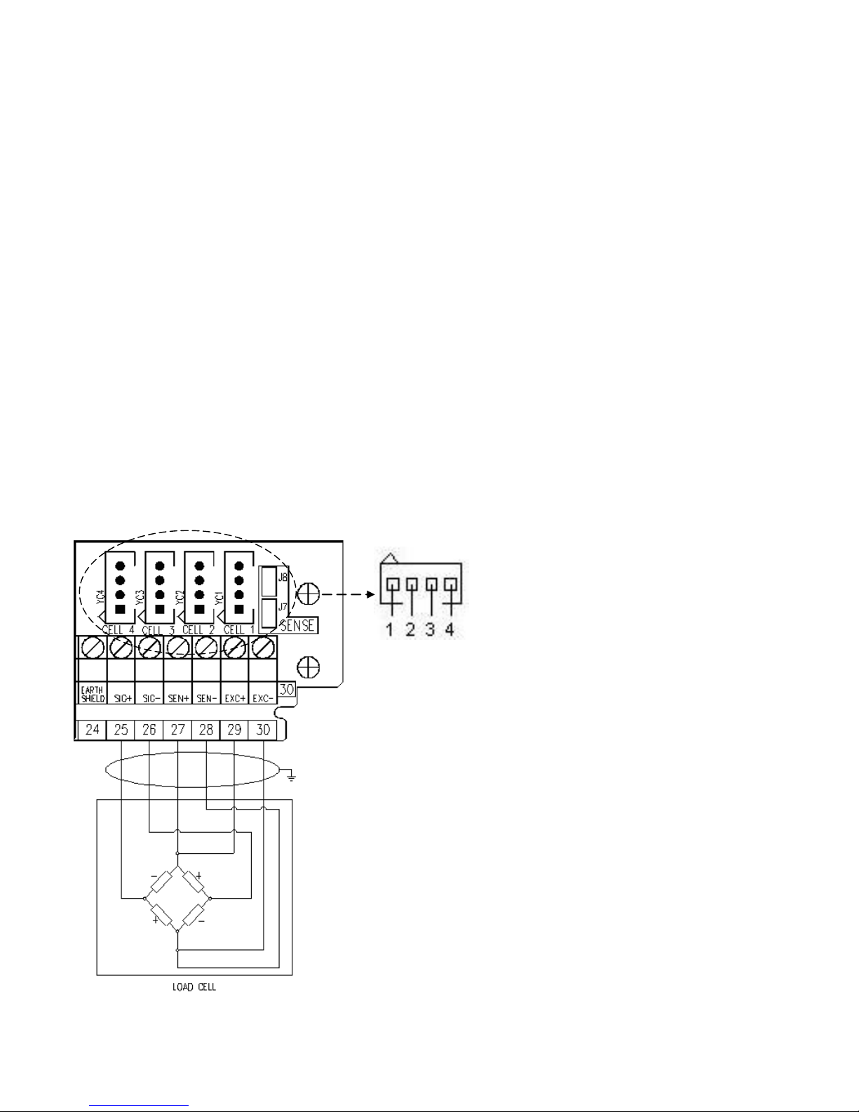
cell(s) must be connected to the instrument through the CELL1 terminal board and the CELL1, CELL2, CELL3, CELL4
connectors; see section 8.
The terminal board of the indicator may be connected to the 6-wire load receiver (with use of SENSE), or simply 4-wire; for
this, through jumper J7 and J8 it is possible to choose whether to short-circuit the SENSE with the POWER SUPPLY
(jumpers closed) or not (jumpers open).
The SENSE allows compensating for any drops in voltage in the part of the cable that connects the instrument to the
transducer. It is useful when the distance between the indicator and the transducer is greater than 10 m.
The 4-pin connectors instead allow just the 4-wire connection.
To make the connection qualified personnel must open the instrument (see terminal board connections section 8).
TAKE NOTE: if there is just one LOAD RECEIVER, it is possible to make a 6-wire connection (use of sense) directly
with the terminal board, removing the J7 and J8 jumpers.
If there are two or more LOAD RECEIVERS, one should close the J7 and J8 jumpers (sense and power supply are
short-circuited) and make the 4-wire connection.
Normally the indicator comes already connected to the platform and is ready to use. If this is a LEGAL FOR TRADE
instrument, access to the connection will be subject to a legal SEAL.
Follow the instructions for preparing the platform for use.
AMP 4 CONNECTOR
1. EXC + POWER SUPPLY +
2. EXC - POWER SUPPLY -
3. SIG + SIGNAL +
4. SIG - SIGNAL -
TERMINAL
25. SIG + SIGNAL +
26. SIG - SIGNAL -
27. SEN + REFERENCE +
28. SEN - REFERENCE -
29. EXC + POWER SUPPLY +
30. EXC - POWER SUPPLY -
See section 8 for further information.

3590EKR, 3590EXP, 3590EXT, 3590 EBOX, CPWE, CPWET series indicator E-AF03_05.01_14.07_EN_T.doc
10
CONNECTION TO STANDARD “DINI ARGEO” FEMALE CONNECTOR
1 EXCITATION +
2 EXCITATION –
3 SENSE -
4 SENSE +
5 SIGNAL -
6 SIGNAL +
7 NOT CONNECTED
8 SHIELD TO BE FOLDER AND PLACED UNDER THE
CONNECTOR CABLE TIGHTENER
2.2 DIGITAL LOAD CELLS
IMPORTANT:
- Respect the electrical precautionary measures indicated in section 1.
- Read carefully and apply what is described in chapter 5.3
After having followed the instructions regarding the platform or the load receivers, the screened cable leading from the load
cell(s) must be connected to the instrument through the COM3 RS485 terminal board.
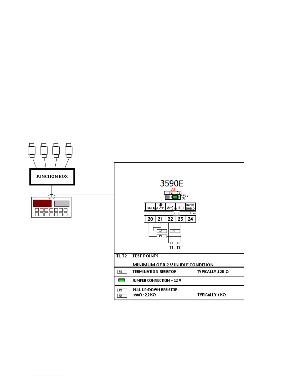
Below is the RS485 connection for digital load cells in the CoM3 of the indicator (with X15 integrated circuit):
TERMINAL MEANING
20. GND POWER SUPPLY -
21. +Vdc POWER SUPPLY +
22. TX+/RX+ Line 485 A(+)
23. TX-/RX- Line 485 B(-)
The voltage value of terminal 21 can be selected through J13 jumper, according to the
required load cells power supply.
The possible selections are 6V or 12V, working if the relative power supply is connected
to the indicator (respectively battery or external power supply, see J13 jumper description
in section 8.1).
Consequently, the functioning with only the battery doesn’t allow the connection of those
digital load cells that require 12V power supply.
In the case of digital load cells connected to a digital junction board, connect the COM3 RS 485 terminal board of the
indicator to the RS485 port of the junction board, by following the relative manual and the section 5.1.
In the case of ring connection of more digital junction boards or DGX, connect the COM3 RS 485 terminal board of the
indicator to the RS485 port of the first junction board/DGX, by following the relative manual and the section 5.1.
3590EKR, 3590EXP, 3590EXT, 3590 EBOX, CPWE, CPWET series indicator E-AF03_05.01_14.07_EN_T.doc
11
2.3 CONNECTION OF LOAD CELLS TO INDICATOR
The load cell has a digital output with an RS-485 interface (4-wire). In regards to the power supply, it needs an external
continuous voltage (CC).
To configure the cells it is necessary to go to the nuM.SCA >> 1 SCALE >> CELtyP step and then choose the type of cell:
AnALoG Cells type analog
dGX Cells type digital DGX
rCd Cells type digital RCD
CCi Ad Cells type digital CCI AD
rC3d Cells type digital RC3D
C16i Cells type digital C16i
WWS Cells type digital WWS
(!)AnALoG
In most cases in order to avoid to make a jumper connection between the cells one uses a junction box which is connected
to the indicator on the terminals dedicated to the 485 port. In between the terminals one needs to apply 2 Pull Up
resistances and a termination one in order to have a minimum 0,2 V voltage between A(+) and B(-) (terminals 22 and 23):
Since each cell uses a filter different than the default one, the functioning speed varies from one load cell type to another.
For the length and section of the connection cables, see the section “MAXIMUM LENGTHS ALLOWED FOR THE
CABLES”
3590EKR, 3590EXP, 3590EXT, 3590 EBOX, CPWE, CPWET series indicator E-AF03_05.01_14.07_EN_T.doc
12
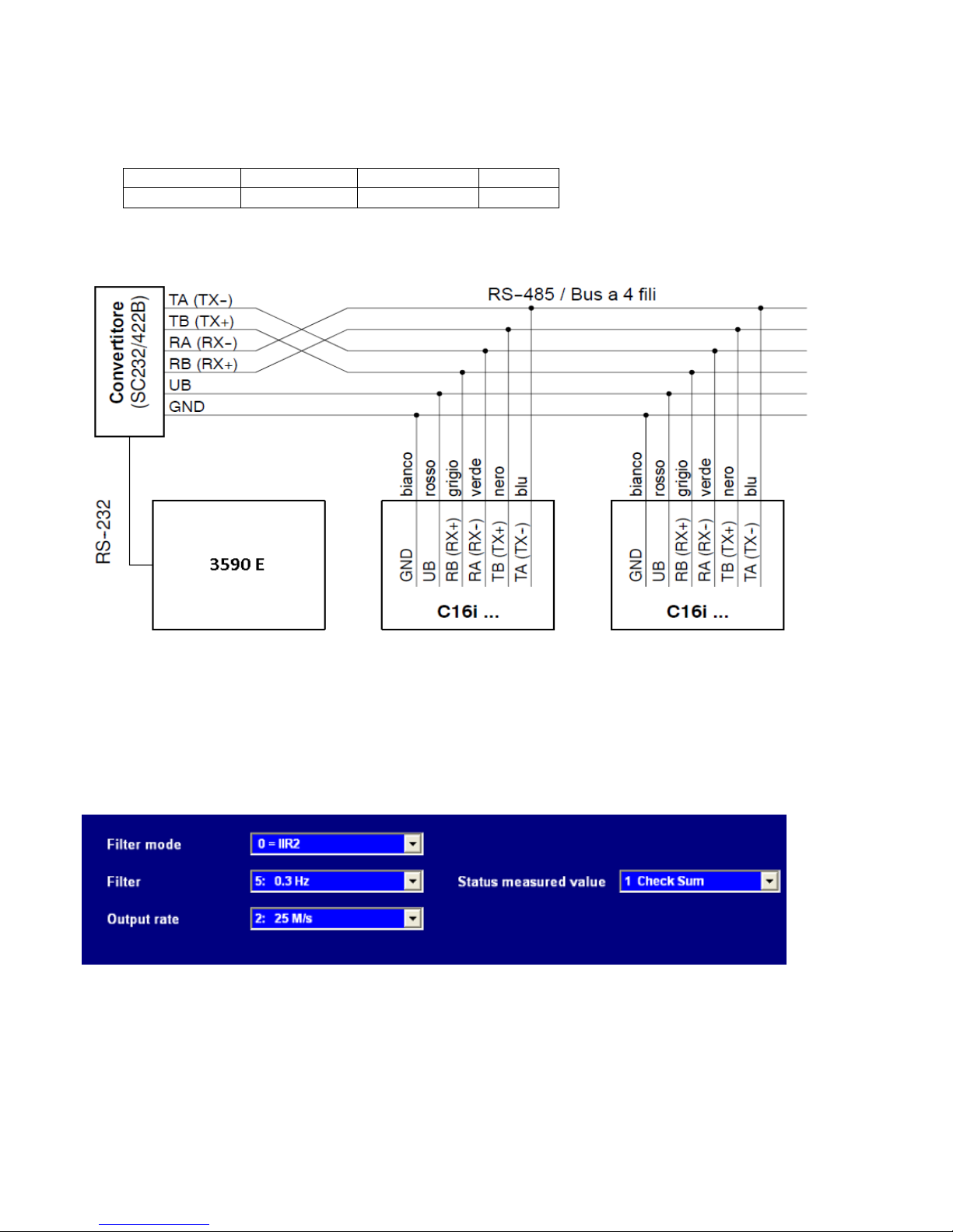
2.3.1 C16i DIGITAL CELL CONNECTION
In order to connect the C16i load cells to the indicator, a SC232/422B converter is necessary so that it is possible to
connect directly on the terminal board in 232 on the pins 14 15 and 16. To do this one should enter in the step SEtuP >>
SEriAL >> PortS and set the ports in this way:
The connection of the cells to the converter are to be made through the junction box or in parallel as described in the
following scheme
For these cells it is necessary to programme a few parameters of the configuration programme of the C16i cell, which may
be accessed by connecting the converter to the PC.
By entering in Parameters >> Basic settings one sets the type of filter one wants to use and the check sum is enabled:
Parameter
COM 1
COM 2
COM 3
AX.Pr.PC
ComAux
ComPrn
ComPC
3590EKR, 3590EXP, 3590EXT, 3590 EBOX, CPWE, CPWET series indicator E-AF03_05.01_14.07_EN_T.doc
13
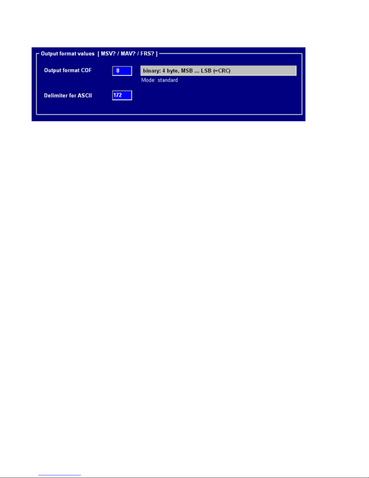
By entering in Parameters >> Communication it is necessary to insert the COF format and the ASCII delimitation as
shown in figure:
Once the type of cell is chosen (SEE 2.3) one needs to enter the number of cells used, and the indicator shows: Cells
Number.
After having chosen the number of cells the indicator automatically enters in the step
SEt.485 Set 485 Address cells
Enter the number of the cell and the relative serial number one after the other and at the end press C. The following
appears:
Snd.CFG Send configuration?
Press Enter and the setting from the indicator is finished.
2.3.2 RCD DIGITAL CELL CONNECTION
Once the type of RCD cell has been chosen, one should enter the number of cells used, the indicator shows: Cells
Number.
After having chosen the number of cells, the indicator automatically enters in the step
SEt.485 Set 485 Address cells
Enter the cell number and the relative serial number one after the other,and at the end,press C. The following appears:
Snd.CFG Send configuration?
Press Enter and the setting from the indicator is finished.
For the connection of the RCD cells to the indicator, a junction box is necessary, which is connected to the indicator
through 485, also necessary two bias resistors. (SEE SECTION “RS 485 CONNECTION)
3590EKR, 3590EXP, 3590EXT, 3590 EBOX, CPWE, CPWET series indicator E-AF03_05.01_14.07_EN_T.doc
14
“ tECh ”
for an instant on
the display
“ uSEr ”
for an instant on
the display
“ tECh ”
for an instant on
the LCD display
Part reserved for the Authorised Technical Personnel
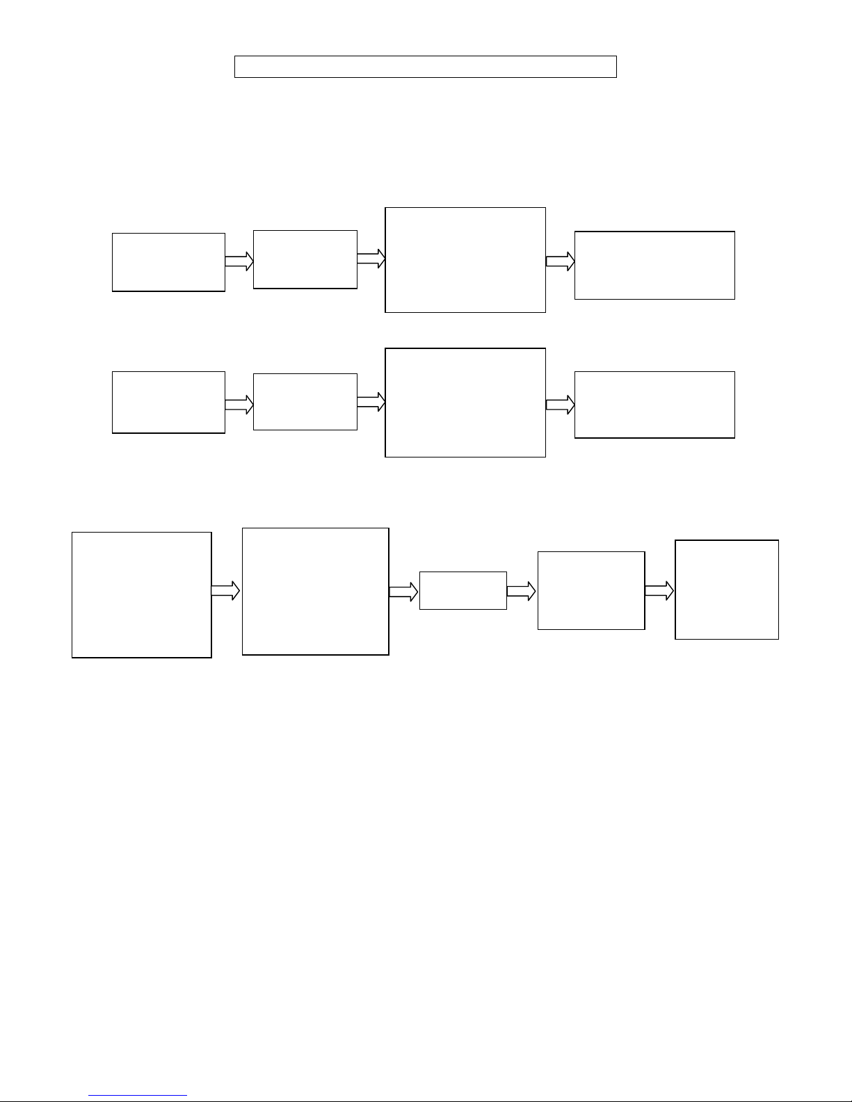
3. SETUP ENVIRONMENT
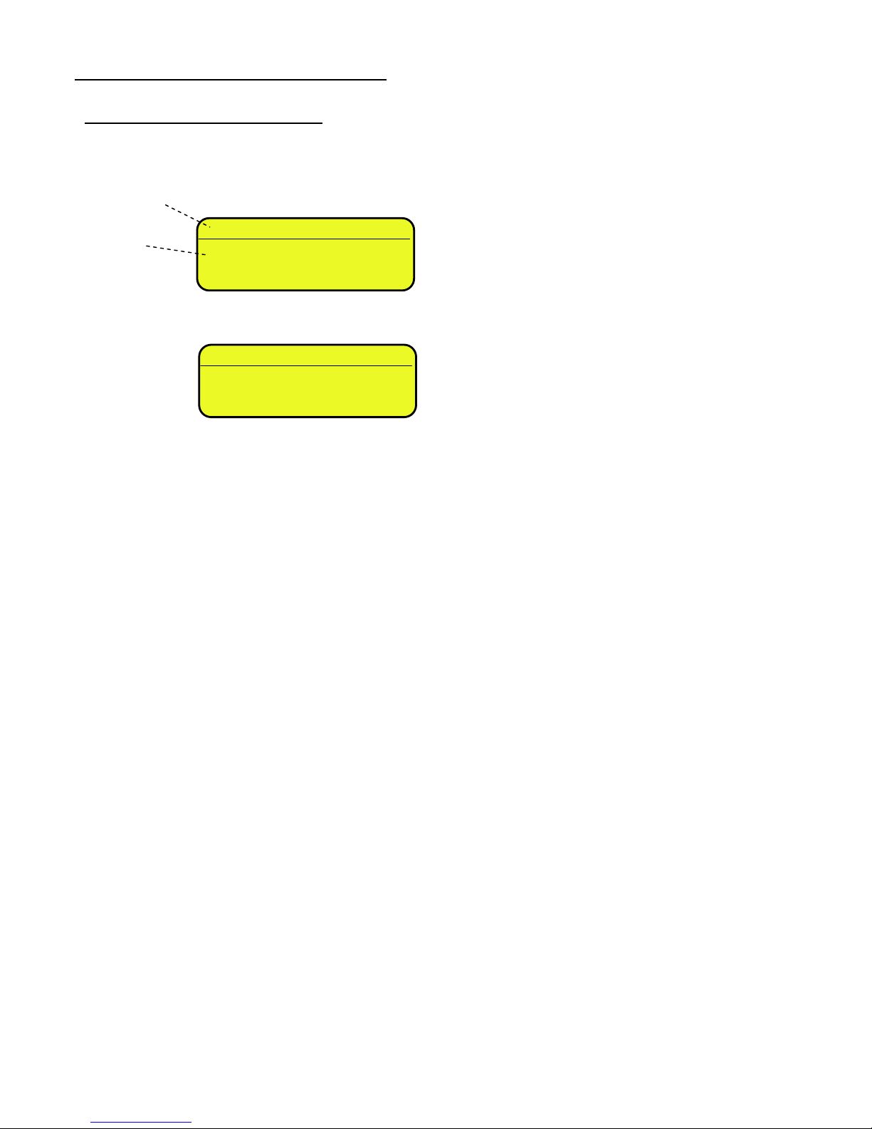
By "SETUP environment" we mean a certain menu inside which all the indicator operating parameters can be set.
To enter it, turn on the instrument and, while the firmware version is displayed, press the TARE key for an instant.
The indicator shows:
1)
Or
2)
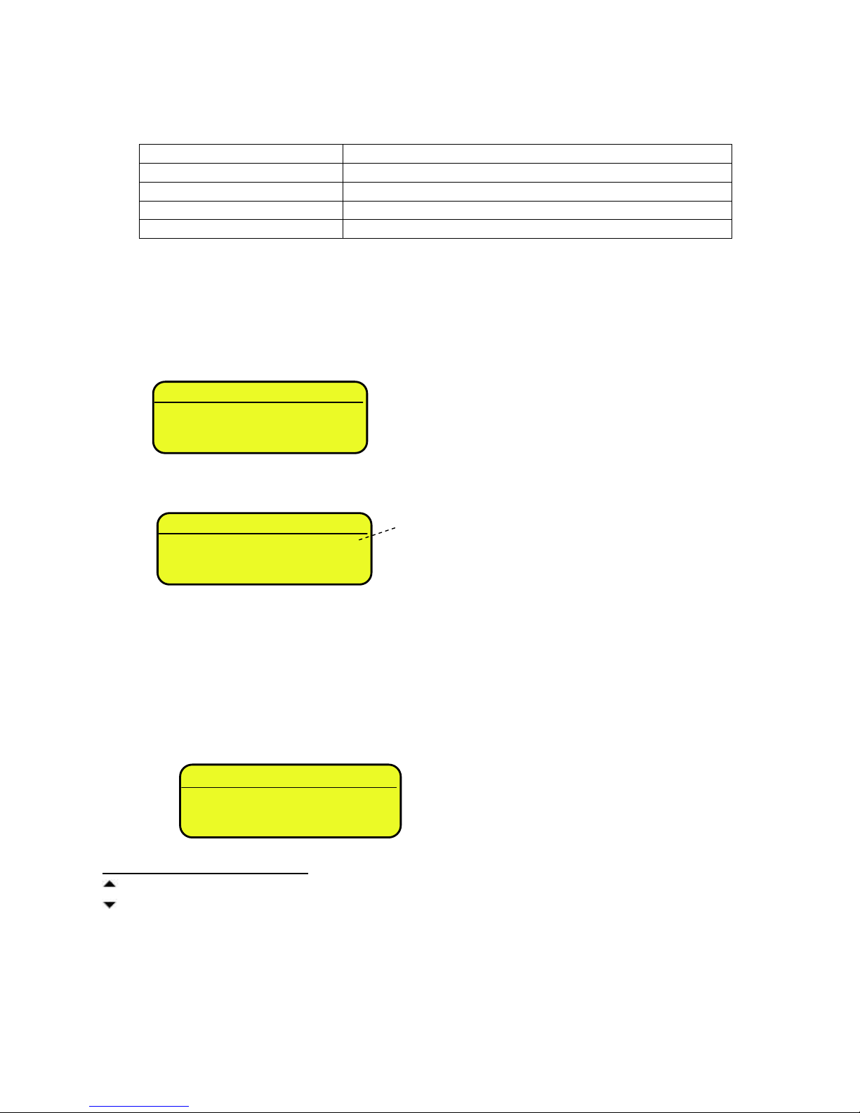
If you are in choice 2) and you want to access the complete set-up menu one should:
(*) If one has forgotten the password, one should communicate the displayed number to the manufacturer, who will supply a
valid password JUST FOR THAT SPECIFIC NUMBER.
In the parameter description and in the block diagram:
- The METRIC parameters are shown with the (*) symbol, and, with approved instrument, these may not be visible
or read only. See the explanation of the parameter for the details.
NOTE: The indicator is approved when the J1 jumper of the motherboard is closed (see the electrical scheme
in the final chapter).
- The CONDITIONAL STEPS are shown with the (§) symbol, and are not accessible or displayed in specific
conditions, shown in the step description.
- The DEFAULT VALUES are shown with the (!) symbol placed next to the step and at the end of it.
“ LAnG ”
on the display on top;
“LANGUAGE”
on the display below
COMPLETE SET-UP
MENU
(technical personnel)
“PrG.VEr”
on the display on top;
“FIRMWARE”
on the display below
PARTIAL SET-UP
MENU
(only user)
ACCESS
PASSWORD
DISABLED
ACCESS
PASSWORD
ENABLED
ENTER THE
PASSWORD
SUBSTITUTING THE
DISPLAYED (*)
RANDOM VALUE
PRESS
“ENTER”
COMPLETE
SET-UP
MENU
(technical
personnel)
Press TARE/ZERO
during the
visualisation of the
“uSEr” message
on the LCD display

3590EKR, 3590EXP, 3590EXT, 3590 EBOX, CPWE, CPWET series indicator E-AF03_05.01_14.07_EN_T.doc
15
FUNCTION OF THE KEYS IN THE SET-UP ENVIRONMENT
KEY
FUNCTION
F6, F7
Allow to scroll forwards and backwards in the menu steps or in the parameters inside a step.
Fn / ENTER
Allows to enter a step or confirm a parameter inside a step.
C / DEL
Allows to exit a step without confirming any changes made and to go to the previous level.
While entering a code, it quickly zeros the displayed value.
F5
It allows to print the entire configuration of the set-up environment (if one is in the main menu), or
to print the configuration of the single step (if one is in the desired step).
The display shows the “PRINT” message: press ENTER to confirm or C to cancel.
NUMERIC
KEYBOARD
Allows entering digits or characters.
The display show the current parameter and its description; generally, when one exits a step the instrument places itself on
the following step.
TO EXIT THE SET-UP ENVIRONMENT, PRESS THE C KEY MANY TIMES UNTIL THE INDICATOR SHOWS:
CONFIRM WITH ENTER TO SAVE CHANGES MADE OR PRESS ANOTHER KEY TO NOT SAVE.
EXITING SETUP:
SAVE ?
3590EKR, 3590EXP, 3590EXT, 3590 EBOX, CPWE, CPWET series indicator E-AF03_05.01_14.07_EN_T.doc
16
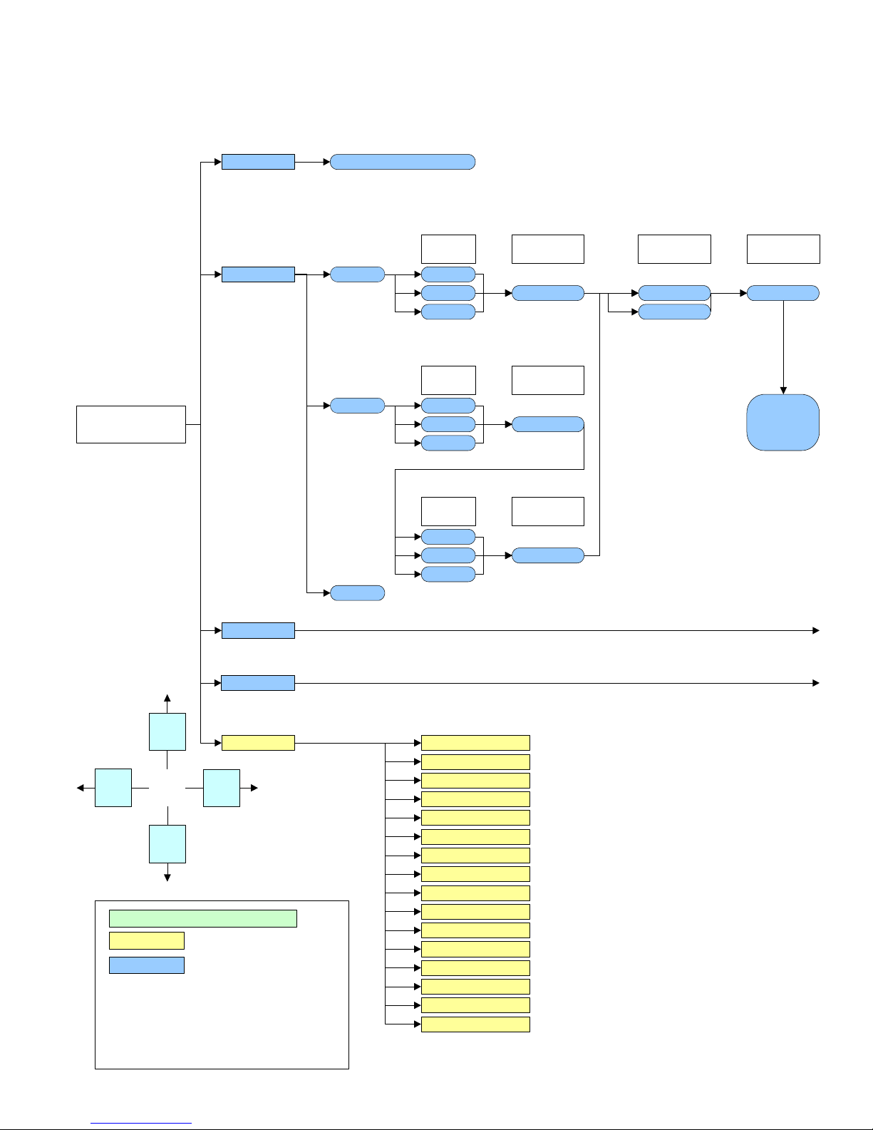
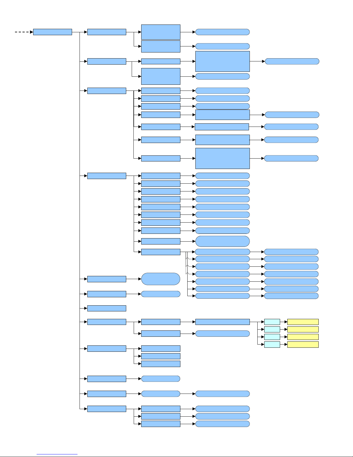
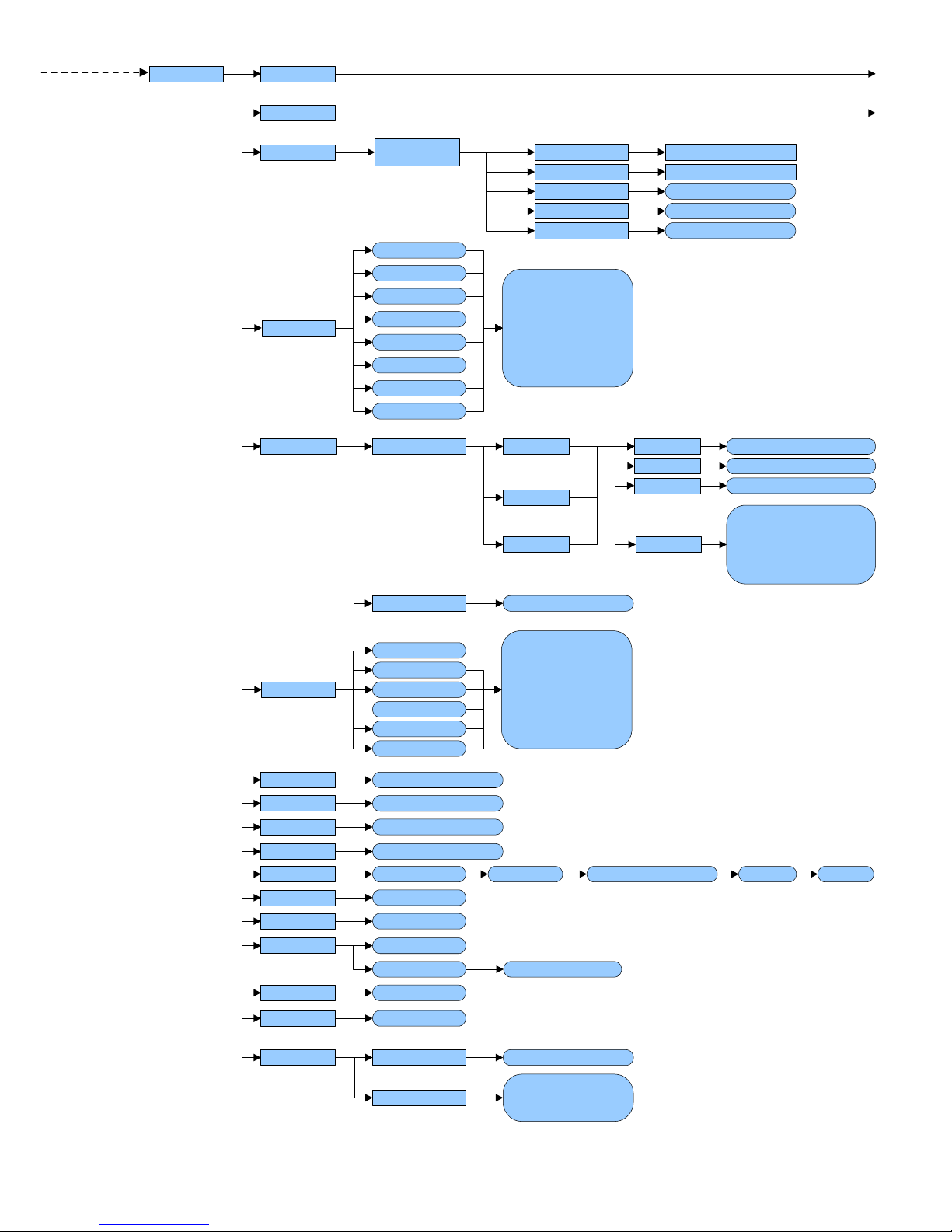
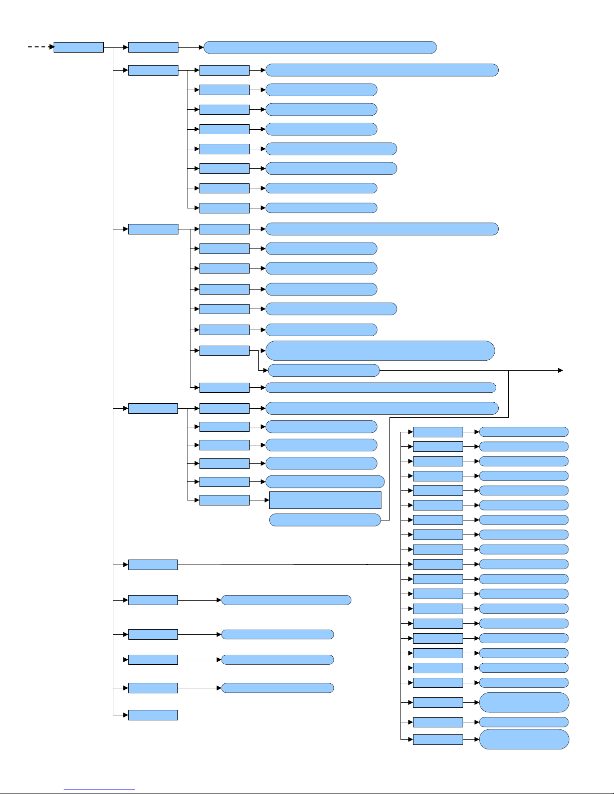
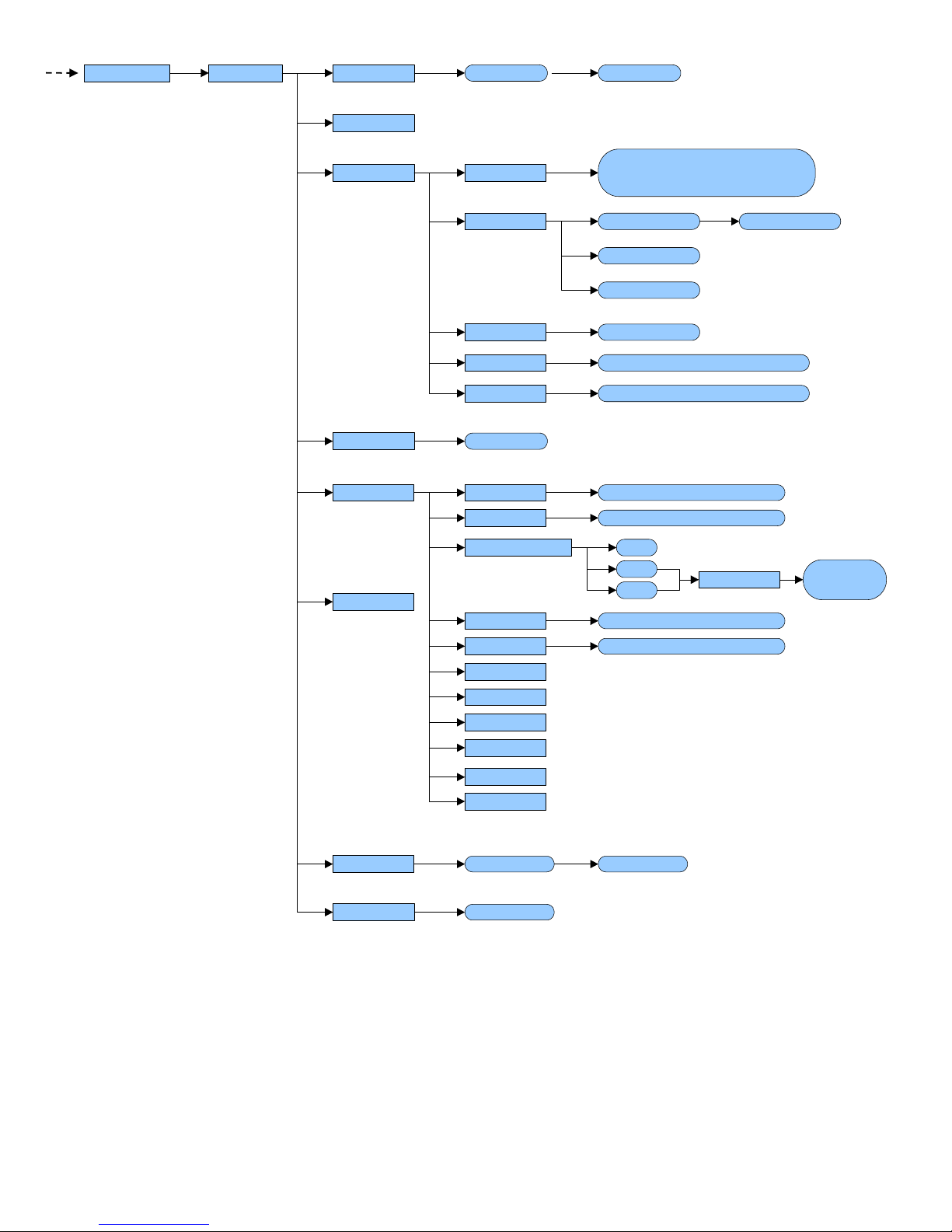
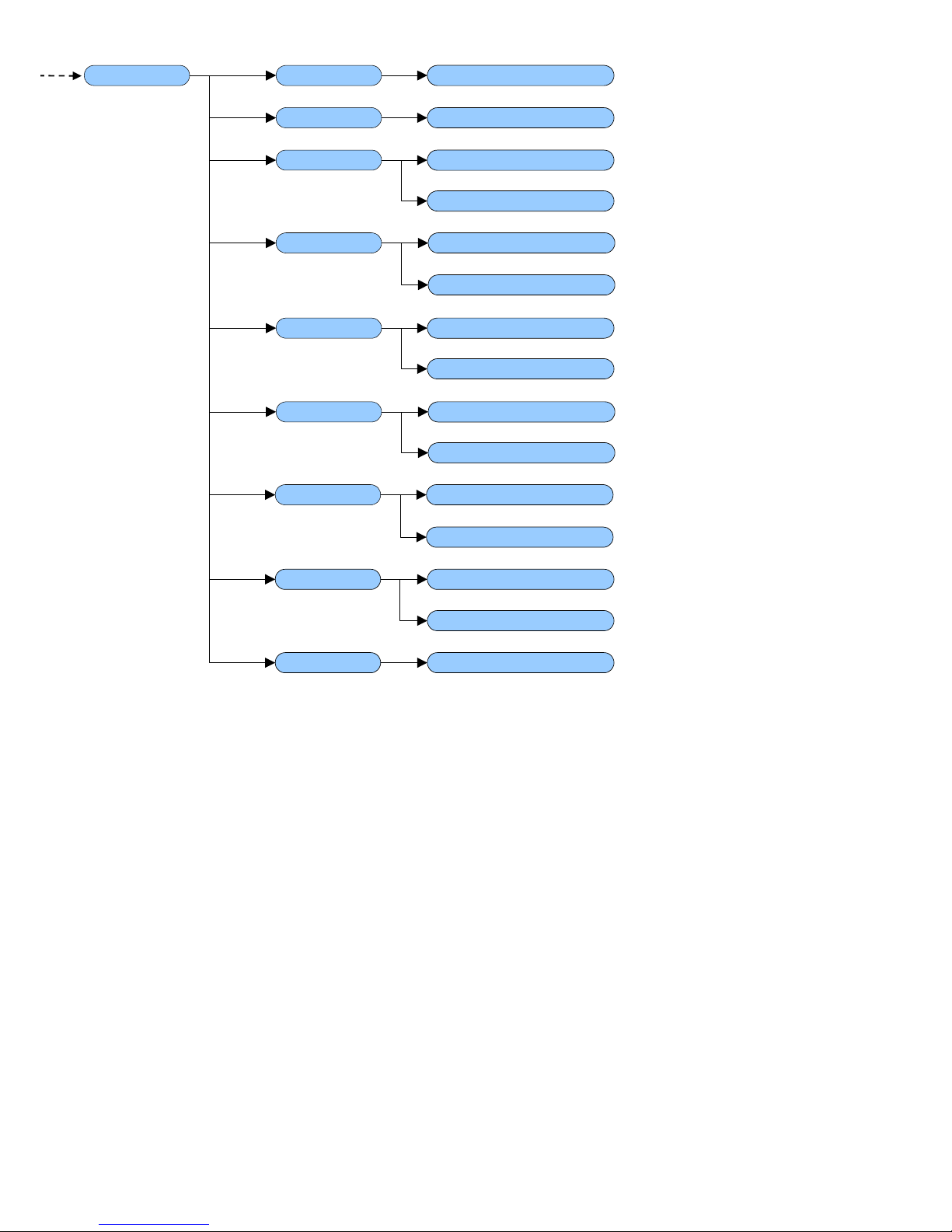
3.1 SET-UP ENVIRONMENT BLOCK DIAGRAM
The following diagram represents the structure of the indicator’s set-up environment; each step has been described in detail
in the paragraph 3.2.
F.ModE
diAG. PrG.VEr
WEiGht
MiLLiV
diSPLA
kEyb.
CtS.St
SEtuP
SETUP
ENVIRONMENT
rELE
inPutS
Anout
= USER & TECH MENU’
= ONLY TECH MENU’
(*) = METROLOGICAL PARAMETER
(§) = CONDITIONED STEP
(!) = DEFAULT VALUE
LEGEND
b.LEVEL
PoWEr
SEr.
SEr.nuM
F7
ENTER
F6
C
LAnG (!) En, Fr, dE, ES, Gr, it
AdC.Pnt
nuM.SCA 1 Scale
Remote
2 Scales
Analog
…
Scaime xx
Cel.typ
Scale 1
Num.Cel
Scale 1
Analog
…
Scaime xx
Cel.typ
Scale 1
Num.Cel
Scale 1
Analog
…
Scaime xx
Cel.typ
Scale 2
Num.Cel
Scale 2
Cel.add
(if at least 1
scale cel.typ is
<> Analag)
M.CELLS xx
J.boX
DGX mode DGX.number
P.tESt
EV.LoG
3590EKR, 3590EXP, 3590EXT, 3590 EBOX, CPWE, CPWET series indicator E-AF03_05.01_14.07_EN_T.doc
17
dtb
rEACt
LoGo
tXt
tXt.i
CLr.rAM
dtb.PWd
tAMAG
AbiL.C
init.
(!) inStAb, PASS.0
CFG.tXt
d.thrES
tHt.i 0
tHt.i 1
tHt.i 2
SurE?
(!) Disable, Enable 00000 … 65534
(!) 00 … 99
(!) 00000 … 99999
MonthS
WEiGh.
F.ModE EN.KEYS (!) Enable, Disable
F1...F10, 0...9,
POINT, TARE,
Fn, 2ndF, C
F.Keys F1…F10 xxx
En.M.Fld
(!) Enable, Disable
YES, NO
DATABASES,
TEXTS,CUSTOMERS
MATERIALS
VEHICLES
ENABLE ALL,
DISABLE ALL
SURE?
(!) 00 … 31
New
Edit
Delete
Print
F1
F2
F3
F5
In. 0 … In. 14
rESEt SurE?
totAL WEi.Mod
i.o.SCA
C.EntEr
(!) nor.WGt, SEC.WGt
rESEt
Wei.MEM
Pro.LSt
rES.tAr (!) Disable, Enable
En.C.Fld (!) Enable, Disable
Add.tAr
Description1
Description2
2nd F+F1…
2nd F+F10,
Fn+F1…Fn+F10
xxx
LIST 1:
:
:
10:
T.ModE
AbiL.M
AbiL.V
(!) Enable, Disable
(!) Enable, Disable
Description2 (!) Enable, Disable
En.V.Fld
Description
Tare
(!) Enable, Disable
A.inout
(!) Wei.Cod, PLAtE
(!) Disable, Enable
(!) MAnuaL, ALWAYS
(!) Enable, Disable
(!) Disable, Enable
(!) FrEE, Set.i.o1, Seti.o2
(!) ConFEr, inVErt
(!) Disable, Enable, Simple
Printout
SELF.C r.S.WGht
dF.WGht
r.Auto0
t.Auto0
t.StAbi
LoCK.K
t.End
XXXXXX
XXXXXX
XXXXXX
XXXXXX
XX
XXXXXX
(!) Disable, Enable
3590EKR, 3590EXP, 3590EXT, 3590 EBOX, CPWE, CPWET series indicator E-AF03_05.01_14.07_EN_T.doc
18
(*) dFLt.t
(*) Ini.AL
(*) d.SALE (!) NO, YES
PoW.oFF
bt.StAt
dFLt
PWd.SEt
tArE t
SURE?
(!) DISABLED, ENABLED
(!) DISABLED, ENABLED
SURE?
SURE?
SEriAL
(!) Lock, Unlock, Disable
SEtuP
Anout
ModE
AoMA
AoZE (!) 00000 … 65535
(!) 00000 … 65535AoMi
SLot (!) SLot 1, Slot 2
(!) AoG, Aon
(!) 00000 … 65535
KEYuSEPC.KEYb
LAYout
(!) Normal, READER
(!) ENGLISH, ELLENIKA,
ITALIANO, FRANCAIS,
DEUTSCH
(*) ConFiG
IN.2
inPutS
outPut rL.1
rL.16
no/nC
onStAt
rLFunC
rL.iSt
r.ConF.
r.ModE
(!) None, TARE, 2nd F,
Fn, POINT, C, F1 …
F10, 0 … 9, PLT-0, PLT-
1, PLT-2, PLT-3, PLT-4,
LOC.IN, OFF, -OK-
ERROR, READY,
START, STOP, RL.OFF,
LNG.KEY, LEVEL,
R.START
(!) n.o., n.C.
(!) drCt, StAbiL
(!) iSt.oFF, iSt.on
(!) nonE, GroSS, nEt, Gro.0,
nEt.0, Motion, totAL, T.W.1,
T.W.2, T.W.3, nEt.nEG, in-
out, WEiGh, t.LiGht
(!) Normal, EXCLUS
inF.rEd
None
IR 4
IR 18
RD 6
(!) None, TARE, 2nd F,
Fn, POINT, C, F1 …
F10, 0 … 9, PLT-0, PLT-
1, PLT-2, PLT-3, PLT-4,
LOC.IN, OFF, -OK-
ERROR, READY,
START, STOP, RL.OFF,
LNG.KEY, LEVEL
...
SCALE1,
SCALE2
00000 … 65534
(!) DISABLED
ENABLED
IN.3
IN.4
IN.5
IN.6
IN.7
IN.8
IN.1
ZOOM.W (§) (!) DISABLED, ENABLED
RD BR 6
bACkuP SURE? PWD XXXXX (!) DISABLED, ENABLED Bak.PWD XXXXX
IR 19
3590EKR, 3590EXP, 3590EXT, 3590 EBOX, CPWE, CPWET series indicator E-AF03_05.01_14.07_EN_T.doc
19
CoMPrn
CoM PC
Add.485
ProtoC
PC.ModE
bAud
PAritY
Word
StoP b
bAud
PAritY
Word
StoP b
Prn.FMt
tErMin
dEF.Prn
CtS.St.
PWrPrn
ProtoC
CtS.St.
ProtoC
CoMAuX bAud
PAritY
Word
StoP b
CtS.St.
PortS
rEM.SCA(*)(§)
rEAdEr
r71.rEP
EnAb.
tErM
WEi.PoS
WEi.LEn
CAPAC.
diV.
dECiM.
u.M.
StAb.
StA.int
Str.LEn
tAr.Pos
tAr.LEn
tAr.tYP
ZEro
tArE
W.tYPE
round.S
MAn.tAr
rEq.WEi
(!) PC.Pr.AX, PC.AX.Pr, Pr.PC.AX, Pr.AX.PC, AX.PC.Pr, AX.Pr.PC
(!) 9600, 1200, 2400, 4800, 19200, 38400, 57600, 115200
(!) None, Odd, Even
(!) 8 bit, 7 bit
(!) 1 bit, 2 bit
(!) LOW, HIGH, EMUCTS, NO.CTS
(!) 9600, 1200, 2400, 4800, 19200, 38400, 57600, 115200
(!) None, Odd, Even
(!) 8 bit, 7 bit
(!) 1 bit, 2 bit
(!) NO.CTS, LOW, HIGH, EMUCTS
(!) 00 … 99
(!) 9600, 1200, 2400, 4800, 19200, 38400, 57600, 115200
(!) None, Odd, Even
(!) 8 bit, 7 bit
(!) 1 bit, 2 bit
(!) DISABLED, ENABLED
(!) Disable, CMd.VAL,
VAL.CMd
(!) DISABLE, COM.PRN, COM.AUX
(!) DISABLED, ENABLED
C.F.01 … 30
(!) LF, NO.TERM, CR, CR LF
(!) PWrint, EXtoFF, PWrEXt
(!) norMAL, riPE 6, ALibi, Cont.
(!) StAnd, AFXX, riPE 6, riPLCd, Mondir, ALibi, SMA, ModbuS, Profi.b,
b tyPE, riP.b, Eth.nEt.riP.b3, riP.b4
(!) rEquE., Cont., StAbiL, - 485 -, End.CYC
(!) NO.CTS, LOW, HIGH, EMUCTS
(!) nonE, Cont., riPE 6, riPEdC,
Ety.nEt
(!) DISABLED, ENABLED
(!) DISABLED, ENABLED
(!) DISABLED, ENABLED
(!) DISABLED, ENABLED
(!) 00 … 99
(!) 00 … 39
(!) 01 … 39
(!) GroSS, nET
000 … (!) 255
(!) 01 … 39
000 … (!) 255
(!) 00 … 39
(!) 00001 … 99999
(!) 001 … 200
0, 1, 2, (!) 3, 4, 5
(!) -g-, -kg-, -t-, -lb-
00… (!) 03, … 20
00… (!) 02, … 20
SEriAL
Err.CtS (!) DISABLED, ENABLED
tErM.tX
(!) CR, CR LF, LF,
NO.TERM
Coin
Coin
3590EKR, 3590EXP, 3590EXT, 3590 EBOX, CPWE, CPWET series indicator E-AF03_05.01_14.07_EN_T.doc
20
StAbiL.PArAM.
ConFiG (*)
Auto 0
0.trACK
diV.Stb
rAnGE tYPE
CAP.1
diV. 1
diV. 2
CAP.2
CAP.3
diV. 3
dECiM.
u.M.
CALib.P
0.CALib
SEL.SCA
CALib.
PointS
CELtyP
GrAV
EquAL (§)
thEo.CA (§)
AdJ.CEL (§)
SLW.0 (!)– 3, H.R.0, H.R.1, FLT 0 – 3,
DYN.0 - 1, DOS.0 – 3, H.R.2 – 7, DYN.2
– 3, FLT.OFF, FLT.AV2, Custom
(!) ENABLED
XXXXXX XX
(!) TR.1/2, TR.1, TR.2, TR. no, TR.1/4
00, … (!) 02, ... 99
(!) 9.800655
nuMbEr oF rAnGE 1
2
3
M.rAnGE,
M.diViS
(!) 1, 2, 5, 10, 20, 50, 100, 200
(!) 100 … 999999
(!) 3, no, 1, 2
(!) - kg -, - t -, - lb -, - g -
XXXXXX XXXXXX
XXXXXX
DISABLED
CYCLIC (§)
(!) 10
0.PErC (!) 02
3590EKR, 3590EXP, 3590EXT, 3590 EBOX, CPWE, CPWET series indicator E-AF03_05.01_14.07_EN_T.doc
21
Coin PriCE.d
SYMboL
bAnd1
(!) 0 … 6
(!) 000 … 255
XXXXXX
XXXXXX
bAnd2 XXXXXX
XXXXXX
bAnd3 XXXXXX
XXXXXX
bAnd4 XXXXXX
XXXXXX
bAnd5 XXXXXX
XXXXXX
bAnd6 XXXXXX
XXXXXX
hiSt (!) 0

3590EKR, 3590EXP, 3590EXT, 3590 EBOX, CPWE, CPWET series indicator E-AF03_05.01_14.07_EN_T.doc
22
3.2 DESCRIPTION OF THE STEPS
<< LAnG >> FIRMWARE LANGUAGE
Parameter Language Used Codepage (see section 7.2)
- En English 1252 Windows Latin 1
- Fr FranÇais 1252 Windows Latin 1
- dE Deutsch 1252 Windows Latin 1
- ES Español 1252 Windows Latin 1
- Gr Ellenika 1253 Windows Greek
- It Italiano 1252 Windows Latin 1
(!) En
<< nuM.SCA >> NUMBER OF CONNECTED SCALES (*)
- 1 scale.
- 2 scales.
- Remote (only remote scale): this value is not visible if one sets the SEtuP >> SEriAL >> rEAdEr on CoMAuX.
(!) n.SC. 1
(*) In case of approved instrument the parameter is read only.
For each connected scale, one is asked to configure the next steps:
<< CELtyP >> CELL TYPE
This menu allows setting the type of cells used (analogue or digital):
in case of analogue cells it will be possible to enter the number of analogue channels.
in case of digital cells / DGX conversion card, it will be possible to enter the number of cells forming the scale and
follow the instructions in section 3.3.6. Only load cells of the same model and the same capacity can compose two
digital platforms.
NOTE: The instrument is able to manage up to 4 analogue channels or 16 digital cells / 16 analogue load cells
converted as digital through DGX conversion cards.
(!) AnALoG
<< DGX.MOD >> DGX FUNCTION MODE
- M.CELLS: Conversion into digital of each single analogue load cell.
- J.boX: for use of the manufacturer.
Follow the instructions in section 3.3.6.
(!) J.boX
<< DGX.NUM >> NUMBER OF DGX CARDS
This menu allows setting the number of DGX composing ALL THE SCALES.
Follow the instructions in section 3.3.6.
<< CEL.Add >> SET 485 CELLS ADDRESS
See section 3.3.7.
3590EKR, 3590EXP, 3590EXT, 3590 EBOX, CPWE, CPWET series indicator E-AF03_05.01_14.07_EN_T.doc
23
<< F.ModE >> SCALE FUNCTIONING
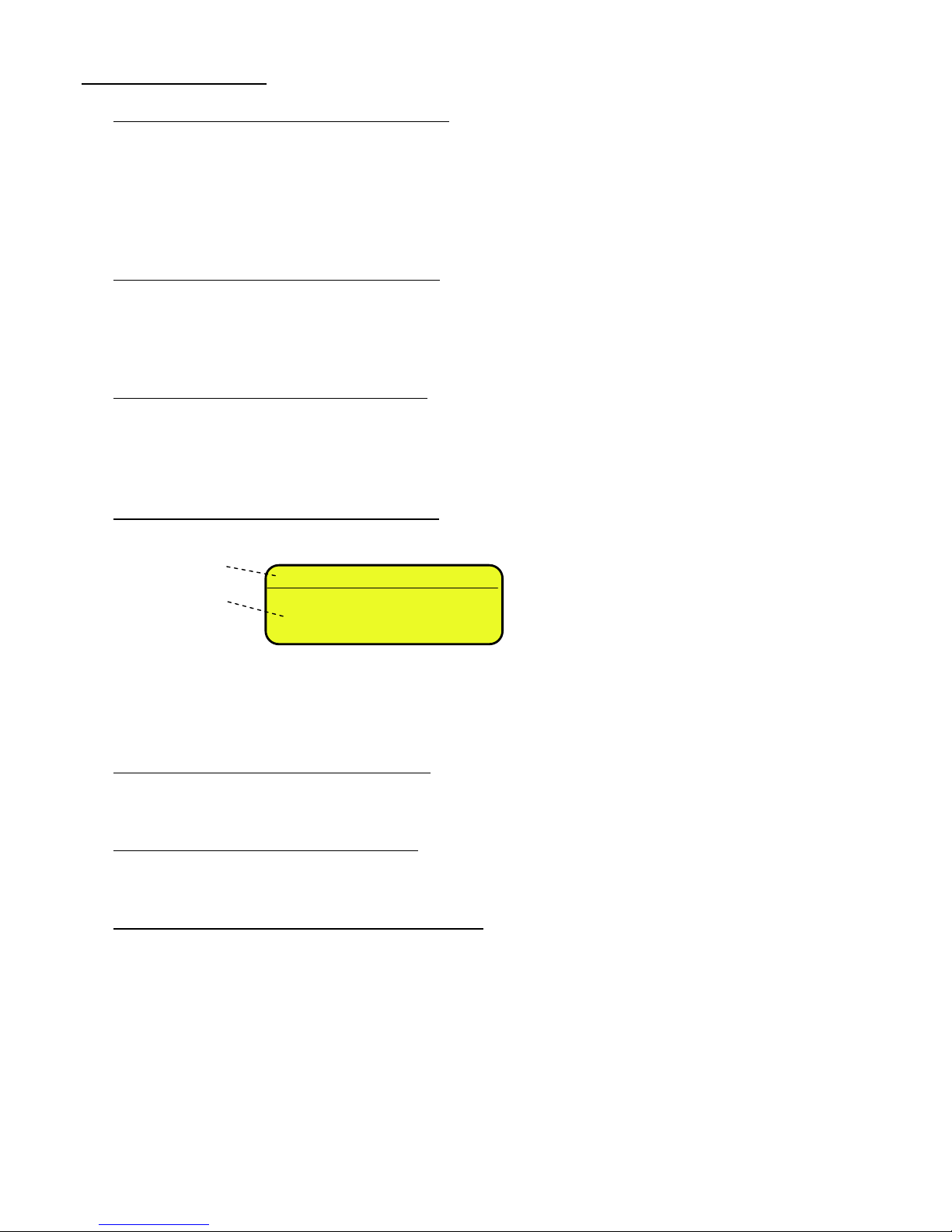
<< En.kEyS >> KEYS ENABLING
It is possible to enable/disable each single key of the keyboard:
- select the desired key with F6/F7:
- press ENTER to modify the setting:
- Press F6/F7 to select “ENABLED” or “DISABLED” and ENTER to confirm.
QUICK FUNCTION RECALL THROUGH 999 + 123 + Fn
If the function 123 + Fn is not enabled, is possible directly recall the desired function with the keys combination 999 +
123 + Fn in weighing phase.
NOTES:
- It’s possible to enable/disable all the keys together, by selecting “ENABLE ALL” or “DISABLE ALL” (the
confirmation will be requested with the message “SURE?”).
- The disabling of the keys will have effect only the WEIGHING PHASE, in other words, not inside the menus,
databases, etc…
- The turning off of the instrument (long pressing of the C key) will always be enabled.
- The disabling of the keys will be applied also on the PC keyboard, if connected.
(!) ENABLE ALL
F1
○ DISABLED
● ENABLED
F1
ENABLED
Status
Key

3590EKR, 3590EXP, 3590EXT, 3590 EBOX, CPWE, CPWET series indicator E-AF03_05.01_14.07_EN_T.doc
24
<< F.kEyS >> FUNCTION KEYS COUPLING
It’s possible to modify the function of the F1, F2…..F10 keys, and the combination of these with the 2nd F or Fn keys
(i.e. “2nd F + F1”, “Fn + F2”, etc...).
Through THE FUNCTION LIST, it is possible to link to a key up to 10 functions, which are executed one after the
other.
F.Keys Default
List
Modify
F1Enter
F2
Enter
Preamble
F.Keys
Enter
- select the desired key with F6/F7:
- press ENTER to see the list:
- press ENTER to modify the setting:
Quick introduction of the maximum and minimum thresholds
It is necessary to associate the function 500 and 501,used for the settings of the totalisation thresholds, each to a
function key between F1 and F10. If one digits a value and then presses one of the programmed keys, the minimum or
maximum threshold is set.
F1
302
Art.dtb
Function
Function
code
Key
F1
302
Code function
(blinking)
Function Code
Function
Preamble
Key
LIST 1: 1+Art.dtb(302)
F1 2: 1+CUS.dtb(305)
3: txt.0(121)
4: NONE
3590EKR, 3590EXP, 3590EXT, 3590 EBOX, CPWE, CPWET series indicator E-AF03_05.01_14.07_EN_T.doc
25
Preamble function
It is possible to associate also a preamble (numeric value) to the F1, F2…F10 keys. In this way, when the key is
pressed, the preamble is automatically used as parameter of the function to be executed.
The functions to which can be associated a preamble are:
FUNCTIONS
PREAMBLE VALUE
Input text configuration (tXt)
Number of the input text that one wants to modify.
Coupling print formats (Prn.Fmt)
Number of the format on which one wants to modify the coupling.
Setpoint configuration (SETPNT)
Number of the setpoint that one wants to modify.
Article database (Art.dtb)
Number of the article that is automatically selected
By pressing a key with the function of an associated database (for example articles database) and the
preamble is enabled to the value 9999, it is required disable the eventually enabled record.
EXAMPLE:
9999 + F1(article database), deselect active article.
- press F2 to insert the preamble:
- select enable and confirm with ENTER
- insert the desired value through the numeric keyboard and confirm with ENTER (by confirming the value 0, the
preamble is disabled).
- If one sets the value 9999 as preamble of a key matched to a database function, by pressing the key the active
record is deselected
KEYS’ FUNCTIONS IN THIS STEP
scrolls backward inside the list of the keys.
scrolls forward inside the list of the keys.
F1 performs the default of the function pairing of the keys.
F2 inserts the preamble.
ENTER modifies the code of the function in the current key; while entering it confirms the enteredcode.
NOTE: by pressing the . /HELP key, it’s possible to display the list of the keys used inside this step and their functions.
The list is automatically shown. If one wants to scroll the list of the keys in manual mode, it is possible to use the arrow
keys (F6 and F7 ).
PREAMBLE
○ Disable
● Enable
PREAMBLE
00000
Preamble value
(blinking)
F1 (2 + F1)
304
Art.dtb
Key (preamble + function)

3590EKR, 3590EXP, 3590EXT, 3590 EBOX, CPWE, CPWET series indicator E-AF03_05.01_14.07_EN_T.doc
26
CODE
BASIC FUNCTION
DEFAULT KEY/S
100
Scale Zero (ZERO)
ZERO
101
Cyclic zero (0.CYCLE)
2ndF + ZERO
102
Tare Execution (TARE)
TARE
103
Activate printer (PRN-ON)
Fn + 0
104
Simple printout (PRINT)
F5
105
Repetition of the last executed printout (CPY.PRN)
2ndF + F5
106
Change weight visualization (WEI.VIS)
2ndF + F8
107
Change visualization on LCD display (LCD.VIS)
2ndF + F9
108
Lock/Unlock the keyboard (L. KEYB)
F1 pressed at length
109
Display of Net Weight with sensitivity x 10 (Disp.10)
F2 pressed at length
110
Setting Date/Time (CLOCK)
F3 pressed at length
111
Diagnostic Menu (Diag.)
F4 pressed at length
112
Lock/Unlock Tare (L. TARE)
F5 pressed at length
113 (*)
Input Texts Configuration (txt)
F4
114
Calculator (CALC)
115
Printout and Reset Partial Total (Prn.0.t0)
F8
116
Printout and Reset General Total (Prn.0.t1)
F9
117
Printout and Reset Grand Total (Prn.0.t2)
F10
118
Diagnostic peripheral units (P.DIAG)
119
Com data diagnostics (COM.DAT)
120
Customized display enabling or change of visualization
if already enabled (CST.DSP)
121
Input text 0 configuration (txt.0)
122
Input text 1 configuration (txt.1)
123
Input text 2 configuration (txt.2)
124
Input text 3 configuration (txt.3)
125
Input text 4 configuration (txt.4)
126
Input text 5 configuration (txt.5)
127
Input text 6 configuration (txt.6)
128
Input text 7 configuration (txt.7)
129
Input text 8 configuration (txt.8)
130
Input text 9 configuration (txt.9)
131
Input text cancellation: from 0 to 14, 99 erase all the
texts (txt.rSt) 132
Print format sending: from 0 to 30 (Send.P.F) OTHER FUNCTIONS
200
Format Linking to the Printout Functions (Prn.Fmt)
201
Format Linking to the Totalisation (SND.FMT)
202
Setpoint configuration (SETPNT)
203
Remote Scale selection (REM.SCA)
2ndF + 0
204
Channel 1 selection (PLT-1)
2ndF + 1
205
Channel 2 selection (PLT-2)
2ndF + 2
209
Change on to next channel (CHG.PLT)
2ndF + 2ndF
SPECIAL FUNCTIONS
300
Input Weigh (IN.WEI.)
F6
301
Output Weigh (OUT.WEI.)
F7
302
Customer database (DB.CUS.)
F1
303
Material database (DB.MAT.)
F2
304
Vehicle database (DB.VEH.)
F3
305
Deselect active records (UNS.ALL.)
2ndF + F4
306
Deselect customer (UNS.CUS.)
307
Deselect material (UNS.MAT.)
308
Deselect vehicle (UNS.VEH.)

3590EKR, 3590EXP, 3590EXT, 3590 EBOX, CPWE, CPWET series indicator E-AF03_05.01_14.07_EN_T.doc
27
309
Select A+B visualization
310
Format Linking to the Input Weigh Printout (FM.IN)
311
Format Linking to the Output Weigh Printout(FM.OUT)
312
Format Linking to the Single Weigh Printout (FM.SING)
313
Customer alpha-betic search (ALP.CUS)
314
Material alpha-betic search (ALP.MAt)
315
Vehicle alpha-betic search (ALP.VEh)
316
Change Of The Second Line Visualization In A+B Mode
(DISP.CH) 317
Network state (nEt.StA)
318
Network monitor (nEt.Mon)
319
Archives alignment (db.ALiG)
320
Unlock weighing list records (unLoCK)
321
Connect network (n.StArt)
322
Disconnect network (n.StoP)
323
Send remote key (rEM.KEY)
324
Send remote long key (r.KEY.L)
325
Remote scale change (rEM.CGH)
VISUALIZATION / PRINTOUT MENU
400
Number of Ticket Copies (CoPiES)
401
Set progressive digits (Prg.1)
402
Set progressive label (Prg.2)
403
Automatic Lot Resetting (0.Prg)
404
Display Customer Total (V.t.Cus)
405
Print Customer Total (Prn.Cus)
406
Reset Customer Total (0.Cus)
407
Reset all Customer Totals (0.CusS)
408
Display Material Total (V.t.Mat)
409
Print Material Total (Prn.Mat)
410
Reset Material Total (0.Mat)
411
Reset all Material Totals (0.MatS)
412
Display Vehicle Total (V.t.VEh)
413
Print Vehicle Total (Prn.VEh)
414
Reset Vehicle Total (0.VEh)
415
Reset all Vehicle Totals (0.VEhS)
416
Display Partial Total (V.t-0)
417
Print Partial Total (Prn.t-0)
418
Reset Partial Total (0.t-0)
419
Display General Total (V.t-1)
420
Print General Total (Prn.t-1)
421
Reset General Total (0.t-1)
422
Display Grand Total (V.t-2)
423
Print Grand Total (Prn.t-2)
424
Reset Grand Total (0.t-2)
425
Reset Scale Totals (0.t-ALL)
426
Reset Weighs List (0.W.LIST)
427
Alibi Memory Reading (ALIBI)
428
Printout and Reset Customer Total (Prn.0.CuS)
2ndF + F1
429
Printout and Reset Material Total (Pr.0.Mat)
2ndF + F2
430
Printout and Reset Vehicle Total (Pr.0.VEh)
2ndF + F2
431
Progressive edit (Pr.Edit)
432
Change the views from KG to Lb and vice-versa
WEIGHING THRESHOLDS
500
Set maximum threshold (tr.HI)
501
Set minimum threshold (tr.LO)
3590EKR, 3590EXP, 3590EXT, 3590 EBOX, CPWE, CPWET series indicator E-AF03_05.01_14.07_EN_T.doc
28
<< dtb >> DATABASES
<< AbiL.C >> ENABLING CUSTOMER DATABASE
It’s possible to enable or disable the CUSTOMER DATABASE:
ENABLED
DISABLED
- Press F6/F7 to select “ENABLED” or “DISABLED”, and ENTER to confirm.
- Proceed up to the last suggested field, after which it automatically exits the step.
(!) ENABLED
<< AbiL.M >> ENABLING MATERIAL DATABASE
It’s possible to enable or disable the MATERIAL DATABASE (like the AbiL.C step):
ENABLED
DISABLED
(!) ENABLED
<< AbiL.V >> ENABLING VEHICLE DATABASE
It’s possible to enable or disable the VEHICLE DATABASE (like the AbiL.C step):
ENABLED
DISABLED
(!) ENABLED
<< En.C.FLd >> CUSTOMER FIELDS ENABLING
It’s possible to enable one by one the fields required for the CUSTOMER DATABASE.
- Press F6/F7 to select “ENABLED” or “DISABLED”, and ENTER to confirm.
- Proceed up to the last suggested field, after which it automatically exits the step.
(!) ENABLED
NOTE: The first customer description is always enabled.
<< En.M.FLd >> MATERIAL FIELDS ENABLING
It’s possible to enable one by one the fields required for the MATERIAL DATABASE (like the En.C.FLd step).
(!) ENABLED
<< En.V.FLd >> VEHICLE FIELDS ENABLING
It’s possible to enable one by one the fields required for the VEHICLE DATABASE (like the En.C.FLd step).
(!) ENABLED
<< init. >> INITIALIZE DATABASES and INPUT TEXTS
By pressing ENTER one initialises the DATABASES (with the total values), the number of decimals and unit of
measure of the databases and the INPUT TEXTS: in this way all their contents will be cancelled.
The cancellation is not immediate; the indicator requests a further confirmation (the LCD display shows “RESET
DATABASES ? ENTER=YES C=NO”).
By pressing ENTER one confirms the operation, by pressing C, the indicator gives the possibility to cancel all the
databases individually in this order: INPUT TEXTS CUSTOMER DATABASE, MATERIAL DATABASE, VEHICLE
DATABASE.
DESCRIPTION2
○ DISABLED
● ENABLED
Name of field
Status

3590EKR, 3590EXP, 3590EXT, 3590 EBOX, CPWE, CPWET series indicator E-AF03_05.01_14.07_EN_T.doc
29
<< totAL >> TOTALIZER
<< WEi.Mod >> SELECTION OF WEIGHING MODE
One selects the type of weighing which one wants to carry out:
nor.WGt NORMAL WEIGHING (simple input/output)
With two scales, by confirming with ENTER one is asked whether to enable the “A+B” mode:
DISABLED
ENABLED
SEC.WGt SECOND WEIGH (input/output with trailer weighing)
(!) nor.WGt
<< WEi.MEM >> TYPE OF INPUT WEIGH MEMORISATION
- WEi.Cod ID CODE
- PLAtE LICENSE PLATE
(!) WEi.Cod
<< Pro.LSt >> LIST OF PROGRESSIVE WEIGHS (only for weighing through ID CODE)
If this parameter is DISABLED, each input weigh is linked to the lowest ID code available; if it is ENABLED, the ID
code following the last input weigh is linked to it.
(!)DISABLED
<< t.ModE >> TYPE OF TOTALISATION
It is possible to select the type of totalisation:
- MAnuAL manual totaliser (reenabling according to how the rEACt “REENABLINGS” step is set.
- ALWAYS totaliser always (always active).
(!) MAnuAL
<< rESEt >> CONFIRM RESET
It is possible to select the automatic resetting of the totals when these are printed (Disable) or the resetting upon
request (Enable).
(!) EnAbLE
<< i.o.SCA >> SETS INPUT/OUTPUT SCALES
With the possibility of connecting a second scale, one sets how the two scales will be used:
SEt.i.o1 BIL1=IN BIL2=OUT: one sets the first scale (in other words, the one connected to the terminal board or to
channel 1) as INPUT, and the second one (in other words the one connected to channel 2) as OUTPUT.
SEt.i.o2 BIL1=IN BIL1=OUT: one sets the first scale as INPUT as well as OUTPUT.
FrEE FREE: one can freely use the two scales as: INPUT in the first / OUTPUT in the second and vice versa, or
INPUT/OUTPUT in the first or INPUT/OUTPUT in the second.
(!) FrEE
<< C.EntEr >> CONFIGURED ENTER KEY
In the “second weigh” functioning mode (trailer weigh), it is possible to configure the ENTER key for acquiring the
weight of the trailer:
ConFEr CONFIRM SCALE: by pressing the ENTER key one confirms the second weigh on the current scale.
inVErt INVERT SCALE: By pressing the ENTER key one confirms automatically switching to the other scale.
(!) ConFEr
<< Add.tAr >> ADDITIONAL TARE
In this step one can enable (ENABLED) or disable (DISABLED) the request to enter an additional tare, at the
moment of the output weigh execution. (USER MAN.REF.).
(!) DISABLED

3590EKR, 3590EXP, 3590EXT, 3590 EBOX, CPWE, CPWET series indicator E-AF03_05.01_14.07_EN_T.doc
30
<< A.inout >> AUTOMATIC IN OUT WEIGHT
In this step you can enable (ENABLED) or disable (DISABLED) automatic input output function or print (SIMPLE
PRINTOUT) when vehicle is selected. When this step is enabled, in the vehicle selection moment is request
automatically the input weight, after, when you reselect the same vehicle will be request automatically the output
weight. This step is appropriate for the SELF SERVICE with badge reader.
In this way when you swipe the badge the indicator identify the veichle and it executes automatically the setted
printout (input/output or simple printout). (REF.NOT.U.)
(!) DISABLED
<< SELF.C >> SELF-SERVICE CONFIGURATION
This step is displayed only if F.ModE >> totAL >> A.inout is enabled (ENABLED) or set to simple printout (SIMPLE
PRINTOUT) or if the protocol COIN is enabled for the COIN on COMPC or COMAUX.
<< r.S.WGht >> WEIGHT THRESHOLD LEVEL INDICATOR: threshold beyond which authentication is required by
badge card or credit to see or ptiny the weight . Beyond this treshold are displayed dashes "-----" instead of weight.
Once you have selected the vehicle (eg. with the badge) or added the credit requested (in case of COIN) displays the
weight on the scale for a maximum time equal to the seconds set in MAX TIME END OPERATION.
(!) 000000
<< dF.WGht >> WEIGHT DIFFERENCE TO WEIGHT THE END: after the acquisistion and display of the weight, if
this increases or decreases by a value greater than this second treshold, the instrument redisplays “------“.
EXAMPLE OF USE:
You have two trucks in line and at the end of the weighing of the first, the second does not make the balance return
to zero. If in this case the treshold is not set in the balance, this one goes in error .
(!) 000000
<< r.Auto0 >> AUTOMATIC AUTOZERO TRESHOLD: treshold (in absolute value) within whch if the weight is
different from zero, remains stable for the time set in the step TIME STABILITY and persist for the time set in the step
TIME AUTOZERO, the instrument perform automatic zero.
EXAMPLE OF USE: you set 40 kg of treshold, TIME STABILITY= 5 s, TIME AUTOZERO = 10 s. If the weight on the
scale is 10 kg and stable, it is reset automatically after 10 second.
(!) 000000
<< t.Auto0 >> TIME AUTOZERO: time in seconds that must elapse before performing the autozero procedure (step
conditional to stability).
(!) 000000
<< t.Stabi >> TIME STABILITY: time in seconds that I have exactly the same weight to be able to declare stable.
(!) 01 sec
<< t.End >> MAX TIME END TRANSACTION: maximum time after which the operation ends. If you perform an
operation and the trucks remains on the weighing, after this time, however, declares ended weighing and requires reauthentication.
Consigliato: 10-20 seconds.
<< t.MonEY >> MAX TIME WAITING CREDIT: (only with coin and protocol COIN enabled) Maximum time to wait the
coin before declare however ended the operation. The time is reset at each introduction of the coin.
(!) 00 sec
LOCK KEYBOARD: if enabled lock all key.
(!) DISABLED
<< rEACt. >> REACTIVATIONS
It is possible to set whether to reactivate the printout and the input/output weigh through:
 Loading...