

Dingsheng Tiangong PY180H Operating Manual

GRADER PY180H
Operating Manual
Product name: Grader
Product specification: PY180H
Add:No.5 Haitai North & South Street,Huayuan Industry Zone of
Tianjin New Technology Industry Zone China
Postal code: 300384
Tel:0086-22-58396099
Fax:0086-22-58396090
The People's Republic of China
Ding Sheng Tian Gong Construction Machinery Stock Co., Ltd

Foreword
This operating instructions is compiled for the grader operator, in order to find
and avoid the personal injury and machine accident, the machine operator shall be
familiar with different rules indicated in this instruction.
The operator shall take this operating instructions when carrying out operation.
The operation, repairs and maintenance shall be conducted by the qualified
personnel.
We can supply training on different models of graders for users at all times.
In order to insure the safety of person and machine, the operator shall do the as
follows:
- The working environment of grader shall be safe and reliable.
- The operation falling short of rules shall be forbidden.
- Report any abnormal phenomenon to higher level and the higher-level
department shall take measures accordingly.
- Refuse unapproved personnel to get on the machine or enter the working site.
- Forbid operating against rules, such as lateral drag, repairing on inclined or
uneven road surface and working under lifted heavy, etc.
- Once the operator take notice of possibility of happening dangers to personnel
or machine, necessary measures shall be taken to avoid accident.
We reverse the rights to make modification to the operating instructions. In case
of minor technical changes, this operating instruction will not be revised and
additional pages will be added to this operating instruction.
The copyright of this operating instruction belongs to Ding Sheng Tian Gong
Construction Machinery Stock Co., Ltd. All Rights Reserved.

Table of contents
1. Preamble .......................................................................................................................................1
1.1 Warranty clause ...........................................................................................................................1
1.2 Spare parts................................................................................................................................1
2. Sales service department...............................................................................................................1
3. Accident prevention ......................................................................................................................1
4. Performance parameter of complete machine...............................................................................3
4.1 Dimensions ...............................................................................................................................3
4.2 Working weight .........................................................................................................................3
4.3 Engine .........................................................................................................................................3
4.4 Torque converter –Transmission.................................................................................................4
4.5 Axle.............................................................................................................................................4
4.6 Tandem box.................................................................................................................................4
4.7 Speed...........................................................................................................................................4
4.8 Brake system...............................................................................................................................4
4.9 Steering system ...........................................................................................................................4
4.10 Hydraulic working system ........................................................................................................5
4.11 Work devices .............................................................................................................................5
4.12 Blade turning device .................................................................................................................5
4.13 Wheels and tyres .......................................................................................................................5
4.14 Front and rear frames ................................................................................................................5
4.15 Driver’s cab...............................................................................................................................5
4.16 Electrical system .......................................................................................................................5
5. Layout and equipments .................................................................................................................6
6. Description....................................................................................................................................7
6.1 Grader .........................................................................................................................................7
6.1.1 Engine ......................................................................................................................................8
6.1.2 Hydrodynamic torque converter-transmission .......................................................................8
6.1.3 Traveling braking (Foot braking) hydraulic system ...............................................................9
6.1.4 Hydraulic operating system and hydraulic steering system...................................................10
6.1.5 Electrical devices ...................................................................................................................15
7. Operation instruction...................................................................................................................16
7.1 Adjust before operating for the first time ..................................................................................16
7.2 Running-in time ........................................................................................................................16
7.3 Diagrammatic representation of control instrument and operating lever of complete machine16
7.4 Driver’s cab...............................................................................................................................21
7.5 Operation of operating device...................................................................................................22
I

7.6 Driving ......................................................................................................................................28
8. Care and maintenance .................................................................................................................33
8.1 Safety rules................................................................................................................................33
8. 2 Lubrication chart ....................................................................................................................34
8.3 Check oil level, change oil and filter ........................................................................................39
8.4 Maintenance system..................................................................................................................45
8.5 Engine .......................................................................................................................................48
8.6 Brake system.............................................................................................................................50
8.7 Adjustment of the chain of tandem box ..................................................................................55
8.8 Lubrication and adjustment of front wheel bearing ..................................................................56
8.9 Work device- Blade...................................................................................................................57
8.10 Tyres........................................................................................................................................59
8.11 Fasten and change wheel.........................................................................................................60
8.12 Steering ...................................................................................................................................61
8.13 Hydraulic operating system ....................................................................................................61
8.14 Transmission shaft...................................................................................................................61
8.15 Electrical device of grader ......................................................................................................61
8.16 Notes to store the grader .........................................................................................................62
9. Fault analysis and troubleshooting..............................................................................................63
10. Front axle drive unit ................................................................................................................72
10.1 hydraulic system of front axle drive........................................................................................72
10.2 Front driving axle....................................................................................................................73
10.3 Operating instructions.............................................................................................................73
10.4 Care and maintenance .............................................................................................................76
10.5 Fault analysis and troubleshooting..........................................................................................76
II

1. Preamble
Our corporation has accumulated an abundance of experiences in complete
machines manufacture in engineering machinery; the grader manufactured by us has
advanced design level and level of technology. If the grader can be used correctly and
maintained properly, the service performance, production efficiency and service life
of the grader will be more reliable, higher and longer respectively.
The trouble-free operation and service life of the grader is depending on the
correct use and maintenance of the grader to a great extent, therefore this manual must
be read by operator and the different operating provisions must be complied with
before the first operation of the grader strictly.
Make sure that the system to be readjusted and the system performance checked
after repair work or replacing parts and components. The above mentioned adjustment
and inspection are very important for the brake system and steering system especially.
We will provide technical service for any necessary repairs upon the sales of the
grader.
GB/T 14782-93 Technical item of Motor Grader.
1.1 Warranty clause
We observe the contact and carry out guarantee of repair; replacement and refund
of substandard products and supply mating parts after the sales of engineering
machinery.
1.2 Spare parts
Make sure that in all repair work, only original spare parts supplied by our
company are used. This gives you the assurance that you will be protected from
damage and your machine will be kept in original conditions.
2. Sales service department
Sales department of Ding Sheng Tian Gong Construction Machinery Stock Co., Ltd
Tel: 008622-58396099
Fax: 008622-58396090
Telegraphic address: 4984
Address: No.5 , Haitai Nanbei Avenue, Huayuan Industrial Area, New
Technology Industrial Area, Tianjin
P.C.:300384
E-mail: export@dstg.com.cn
3. Accident prevention
1) When disassembling and assembling the grader, the works shall be done under
instruction of special technicians.
1

2) The person who received the driver’s license for the grader and is fully familiar
with the operation of the grader can operate the grader.
3) The grader driver must control the grader under good condition.
4) Before driving grader for each day, the driver must check the function of braking
and steering devices.
5) The grader driver shall report the abnormal phenomenon found to maintenance
and repair men and tell the next shift of person. The machine must be stopped if the
abnormal phenomenon brings about unsafe factors to operation.
6) Different control levers of grade can only be controlled in driver’s cab.
7) Make sure to insure the stability of grade during the whole operating process.
8) Must engage gear on downhill path.
9) The safe distance must be kept during operating process and working on busy
road.
10) The driver must take notice that there is no person near the grader before
operating and driving the machine and sound the horn.
11) If cannot see the blade working, the driver shall use flag signal or take
measures necessary.
12) This method can only be used for the driver who is familiar with flag signal.
13) When the grader is operating, any person is forbidden to enter the working area.
14) The operating device shall be fallen to the ground or fixed in case of down time
or not used.
15) Only when setting the grader to the ground or fixing the grader can the diver
leave and set the control device to their original positions.
16) The drive must have the hand brake engaged and all assistant safety devices
locked before leaving the driver’s cab.
17) After work interrupted or completed, shut down the engine and take off the
ignition key as well as switch off the main power switch (if equipped) to avoid
accidental starting.
18) The relevant personnel can go out or enter into the driver’s cab only when
approved by the driver and the grader is parking.
19) It is not allowed for the driver to let the unapproved personnel to enter into the
driver’s cab.
20) When repairing the grader, you should follow the steps as follows:
a) Shut down the engine and put all work devices on the ground or have them
firmly fixed.
b) If you must work under lifting device, the device must be locked or fixed.
c) Because of articulated-steering structure, front and rear frames must be locked.
d) When there is pressure in hydraulic system, don’t turn the joints.
e) After repairing, all safety devices must be returned to original positions (cotter
pins, etc).
It is very important for accident prevention to comply with above-mentioned
rules.
2
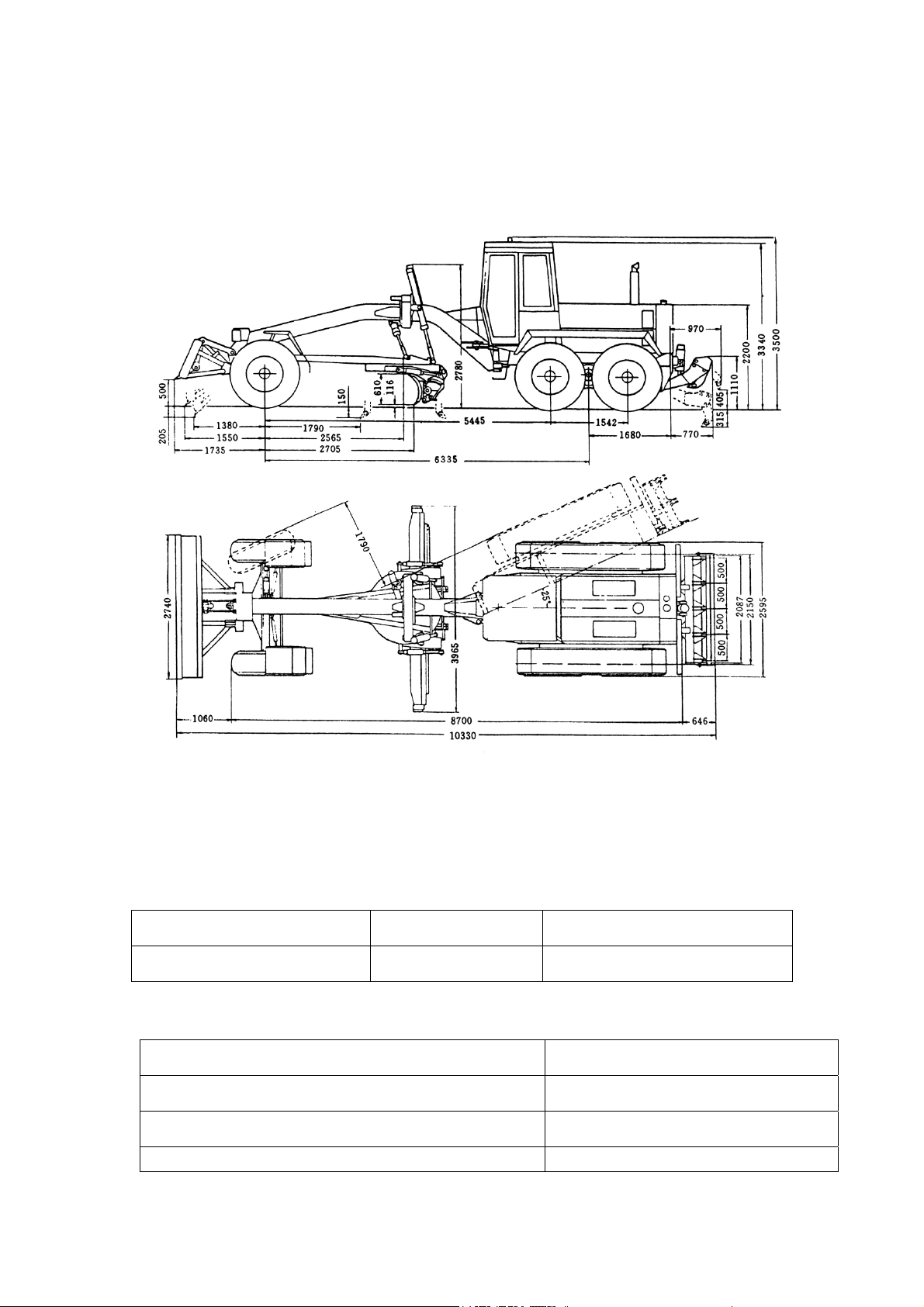
4. Performance parameter of complete machine
4.1 Dimensions (Fig.1)
(Tyre 17.5-25)
Fig.1
4.2 Working weight (Unit: kg)
Complete machine Front axle Rear axle
15400 4600 10800
4.3 Engine
Type 6CTA8.3-C215
Bore×stroke 114×135mm
Total displacement of the pistons 8.27L
Rated power 160kW
3

Rated speed 2200r/min
Max. torque 872N.m
Max. torque speed 1500r/min
Operations sequence of different cylinders 1-5-3-6-2-4
Generator 24V/35A
4.4 Torque converter –Transmission
Type: ZFW320 torque converter (with free wheeling) is integrated with 6WG200
transmission.
Direction change (power gear shifting): Forward gear –neutral gear – reverse gear
Speed gear (power gear shifting): Forward 6 speeds; Reverse 3 speeds.
4.5 Axle
4.5.1 Driving axle
Type: 3-stage driving axle with “no-spin” differential gear.
4.5.2 Driven axle
Type: Oscillating and steering front axle of box type, oscillating angle ±15°,
leaning angle of front wheel ±17°, steering angle 45°.
Ground clearance from center: 630mm
4.6 Tandem box
Type: Oscillating type tandem box, oscillating angle ±15°, heavy-duty roller
chains drive.
4.7 Speed
Forward (km/h) Reverse (km/h)
1st 2nd 3rd 4th 5th 6th 1st 2nd 3rd
5.23 7.94 11.84 17.85 25 40 5.23 11.84 25
4.8 Brake system
4.8.1 Service brake (foot brake)
Pipe system: Brake system consists of one circuit, hydraulic pump and
accumulator.
Brake: Pliers disc brakes are assembled on rear wheels. 4 on two front wheels; 2
on two rear wheels.
4.8.2 Parking brake (hand brake)
Type: Hub brake, mechanically operated and mounted on drive shaft of gear box.
4.8.3 Continuous service brake
The torque converter is designed to conduct continuous service brake.
4.9 Steering system
4.9.1 Front wheel steering
Feature in structure: Hydraulic oil from oil tank is obtained by gear pump to
supply hydraulic steering-gear which distributes hydraulic oil to steering cylinder.
Service pressure: 15MPa
Steering angle: 45°
Turning radius: Without wheel lean 10.9m
4

With wheel lean 10.4m
4.9.2 Articulated frame
System: The articulation operation between front and rear frames is driven by
double acting hydraulic cylinder.
Articulating angle: Right and left sides 25° respectively.
Min. turning radius with articulating steering: 7.8m over the front wheel.
4.10 Hydraulic working system
System: Hydraulic system of double pumps and double circuits.
Control valve: Two valve blocks, each is composed of 5 control valves.
Working pressure: 16MPa (180MPa while blade rotating and with front scraping
plate)
Hydraulic pump: Double-gear pump of high pressure mounted on power output
shaft of the gear box.
Cylinder: Double-acting hydraulic cylinders.
4.11 Work devices
System: Hydraulic adjustment of blade/back ripper and front bulldozing plate,
ring-gear with rolling plate, scarifier with 6 teeth mounted on blade back.
4.12 Blade turning device
Features in structure: worm gears are driven by hydraulic motor, there are two
types of structures, tooth ring or rolling disc.
4.13 Wheels and tyres
Rims: 14.00/1.5-25 (TB)
Standard tyres on all 6 wheels: 17.5-25 PR12
4.14 Front and rear frames
Construction: Front frame – steel beam structure, its section is pressed into
U-sleeve, welded like box.
Rear fame – solid beams welded in two sides.
4.15 Driver’s cab
Structure: Weld structure of the steel is conformed to the DIN AND ISO standards.
The driver’s cab is structure of preventing tipover and sliding down
(ROPS/FOPS), two sliding doors.
4.15.1 Driver’s seat
Structure: Spring vibration absorbing seats, adjustable in horizontal and vertical
position and in back rest inclination.
4.15.2 Air conditioning system
The system is configured according to the user’s requirement. The air
conditioners are heating and cooling devices designed specially for engineering
machinery. Before using air conditioner (for heating or cooling), please read the
instruction of air conditioner carefully.
4.16 Electrical system
Working voltage: 24V
Fuses: 5A, one piece; 10A, 5 pieces; 15A, 3 pieces; 20A, 2 pieces; 25A, 1 piece.
5
Batteries: every one 12V, 165AMP/h.
Lights: head lights 2; tail lights 2; flashlamps 6; brake lamps 2; working lights 2;
rear view lamps 2.
Sound signal: horn
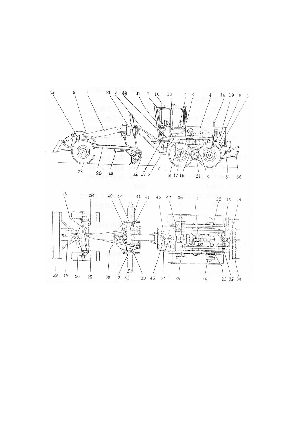
5. Layout and equipments
Fig. 2
Frame and accessories:
1. Front frame 2. Rear frame 3. Articulation center 4. Engine cover 5. Splash guard
6. Driver’s cab 7. Driver’s seat 8. Air conditioner (optional) 9. Mark plate
10. Instrument plate 11. Removable console
Engine and accessories:
12. 6-cylinder-diesel engine 13. Air filter 14. Exhaust system 15. Fuel tank
Gear box, axle, wheel:
16. Driving shaft 17. Torque converter-transmission 18. Gear change lever
6

19. Torque converter oil cooler 20. Front axle 21. Rear axle 22. Tandem box
23. Front wheel
Steering:
24. Hydraulic steering-gear 25. Steering pump 26. Steering cylinder
Work devices:
27. Swing frame, 6 adjustable positions 28.Traction frame
29. Tooth ring with rolling disc 30. Blade turning hydraulic motor 31. Blade
32. Scarifier 33. Front bulldozing plate (front additional weight)
34. Back scarifier (Rear additional weight)
Hydraulic system:
35. Hydraulic tank 36. Working pump
37. Control valves (2 blocks) 39. Hydraulic cylinder, blade lift
40. Hydraulic cylinder, blade swing 41. Hydraulic cylinder, blade shift
42. Hydraulic cylinder, blade cutting angle 43. Hydraulic cylinder, wheel lean
44. Hydraulic cylinder, front bulldozing plate 45. Hydraulic cylinder, back ripper
46. Hydraulic cylinder, articulation
Brakes:
47. Brake accumulator 48. Brake pedal 49. Brake
50*. Relief pressure valve of the accumulator 51. Hand brake (disc brake)
Electrical devices:
52*. Batteries (left side of the engine) 53. Head lights
54. Tail lights 55*. Indicators, instruments, switches and cables
* Not shown in figure.
6. Description
6.1 Grader
The engine and transmission are mounted on the rear frame. The work devices are
mounted on the front frame. The additional front bulldozing plate can enlarge the
scope of application of the grader.
The grader is driven by water-cooling and turbo-change diesel engine that is
composed of 6 cylinders straight line and 4 strokes.
The power produced by engine is transmitted to the rear axle by hydraulic torque
converter, transmission and driver shaft, then to the 4 rear wheels via the tandem
chain.
The hydraulic steering for front wheel is combined with articulating frame giving
the frame a minimum turning radius of 7.8m.
The nouns such as “Left, Right, Front, Rear” describing directions used in this
instruction in relation to the forward direction of grader.
7

6.1.1 Engine
All driving devices (Engine-transmission) are fixed on the rear frame by 6 rubber
vibration reduction housing.
Viewed from the engine fan, the direction of the crankshaft is clockwise.
The combustion air is drawn through an air filter.
Lubrication of all bearings in the engine as well as cooling of some running
engine parts is conducted by forced feed lubrication. The lubrication system is fed by
a pump drawing oil from the engine oil sump.
The engine oil is cooled by internally hidden oil cooler mounted in the engine. For
details please refer to the operating instruction for diesel engine.
6.1.2 Hydrodynamic torque converter-transmission (ZF6WG200)
The ZF6WG200 hydraulic transmission is composed of torque converter and
dead-axle and multi-gear transmission of constant shaft, with the speed of 6 forwards
and 3 reverses.
The torque converter is simple 3 units construction with no-lock clutch, the circle
diameter is Φ 340,the torque coefficient Ko=2.55 at the lost speed. The torque
converter pump wheel is directed mounted on the engine fly-wheel by means of
spring plate. the oil temperature should be 80~110℃ when at normal work and it is
allowed to reach 120℃ at moment.
The transmission has 6 multi disk clutches controlled by hydraulic which can
engage and disengage under the load reach the power shift. The transmission gear is a
constant engagement drive. Its construction and principal can be seen in the following
attached figures The speed ratio of the transmission as follows:
Forward Reverse
1st 2
nd
3
rd
4
th
5
th
6
th
1
st
2
nd
3
rd
5.986 3.904 2.594 1.692 1.178 0.768 5.906 2.594 1.178
There are two pumps outside the transmission. They are dived by pump wheel of
torque converter. Output shaft of the transmission is combined with driving axle
backwards to transmit power to the rear axle. Output shaft is connected to the driving
shaft backward and transfers the power to the rear axle. Output shaft is linked to the
parking brake forward.
The gear shift of transmission is operated by electro-hydraulic shift (hand control
selector) at driver’s right side. The gear shift changes can be achieved by each
electro-magnetic valve connected to hand selector and then to control hydraulic
sliding valve.
Note! Here the user shoult notice that the operation should be done
gradually and sequentially without humping over any gear.
Besides, the transmession can achieve reverse control only in 1st gear.During
8

driving and sliding slope, the corresponding gear shall be controlled and the engine
speed shall not be lower than 1200r/min to meet the needs of lubrication of each part
of the transmession.
The operating pump for suplying oil to torque converter and operating is
mounted inside transmession and aslo controlled by pump wheel. Its flow is
35L/1000r/min,control pressure is 1.6~1.8Mpa (Liuzhou Transmession). Because of
the cushion construction inside the controlling valve, so the pressure of lowering and
rising should have a regularity. During gear change, in this way the geat change can
be smooth and less shock.. Besides, because of “Neutral insurrance” set in
transmession electric circuit, the driver can start the engine when the transmession is
in neytral, so this can prevent from mis-controlling.
The diesel lubrication oil L-ECD15W-40 is applied in this transmession. Filling
oil of the first time is about 28L. When checking oil level, the engine should be in idle
spped and transmession temperature is in normal working condition. At this time, two
oil scales indicate the levels 80℃(Upper scale) and 40℃(Lower scale). The oil level
will be higher than upper scale if check the engine without starting the engine.
Note: The transmission oil must be changed after operation of the
first 100 hours and later every 1000 hours or at least once a year. The
oil filter also should be changed with oil changing. Please notice that
the used filter could not be assembled again even no apparent
damage found.
Note: When the engine is shut down and the main machine is dragged,
this transmission require that the traction distance and speed of
grader cannot exceed 10km and 10km/h respectively.
Note: When conducting electric welding work on the main frame, the
gear selector circuit must be disconnected to avoid damaging its
internal circuit by unexpected over-current.
6.1.3 Traveling braking (Foot braking) hydraulic system (As shown in Fig. 9)
The foot brake has a one-circuit system with hydraulic pump and accumulator and
operates on four rear wheels of the grader.
When the engine is running, the double pump (2) of the working hydraulic draws
oil from the tank (4).
The oil from the pump is transmitted via the pressure limiting valve (9) into two
accumulators (11) to increase the pressure below 133 bars and to cut off oil when 150
bars.
Filling oil of the accumulator (11) requires only short time and then oil intaking
system makes oil flow into hydraulic circuit (130 bars).
The filling oil of the accumulator (11) has priority and therefore, the pressure oil
necessary for the braking system is available as soon as the engine is running.
9

When the pressure on the brake valve (10) drops below 100 bars, the indicator
lamp on the instrument panel lights. This lamp is controlled by controlling the power
switch. The pump is switched by brake service switch.
When pressing down the brake valve (10), pressure oil in the accumulator circuit
flows to the wheel-side brake (12). At the same time, the brake lights are switched on
by the brake light switch.
6.1.4 Hydraulic operating system and hydraulic steering system
a. Hydraulic operating system
This hydraulic operating system is composed of double pumps and double circuits
(Fig.9). It is made up of closed oil tank (4), a two-gang gear pump (1), two five-gang
multi-way reversing valves (Refer to 14, 15), hydraulic cylinders for operating
apparatuses, motor and hydraulic lines. Each system has its own hydraulic pump, but
the hydraulic oil is supplied from the same oil tank (4). The hydraulic oil from oil
tank (4) is pumped by a two-gang pump (1) into two circuits. Among them, oil flows
are equal. When multi-way reversing valves (14, 15) are in central position, the
hydraulic oil, passing through returning lines and the filter (6), returns to oil tank (4).
When moving one or two operating levers, hydraulic oil pushes one-way valve in
reversing valve to flow into hydraulic cylinders and motor. The action of one-way
valve prevents the oil in working apparatus from return oil tank (4).
It can insure that hydraulic system in correct working condition. The double
direction hydraulic lock (16) mounted on the returning lines for titling and lifting the
blade can guard against moving due to their own weight and the load to insure safety
running and operating accuracy of the blade.
Because of the supplying oil in the equal flow, double lift cylinders for up and
down operation in the simultaneous and same speed to raise operating performance of
the grader. System pressure is controlled by the throttle valve in reversing valve (14,
15) .The pressure value is16Mpa and system flow: 65L/min.
b. Steering system
When the hydraulic steering-gear (8) needs the oil, the oil from the oil tank (4) is
intaken by the steering pump and delivered. When turning the steering wheel, the oil
enters into two steering cylinders to make double front wheels steering. Double front
wheels are connected by a common pulling lever.
With safety valve (7), the oil pressure of steering system is limited in 150 bars to
guard steering system. Double safety valves (13) prevent hydraulic steering system
from over pressure. For example, because of the overload caused by road dump, it can
be transmitted from front wheels to steering system.
The oil tank (4) is equipped with pre-pressure air filter that can prevent the air
with dusts from entering into the oil tank and contaminate the hydraulic system.
If the return filter (6) is blocked and the oil cannot flow, the filter valve (5) allows
the oil over the filter from by pass-way and therefore it eliminates the block action of
the filter element. The micro- measuring coupler in the system allows gauge to be
fitted at various positions in the system to adjust the pressure.
10
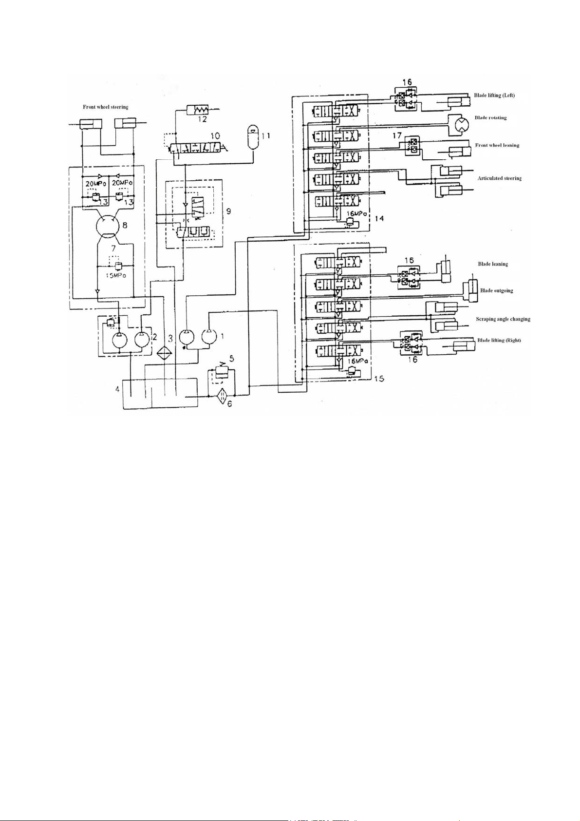
Fig. 9 Service brake, hydraulic operating and steering systems
1. Double-gang operating pump
2. Double-gang operating pump for
steering and braking
3. Return oil cooler
4. Sealed type oil tank
5. Filter valve
6. Return oil filter
7. Steering safety valve
8. Hydraulic steering gear
9. Pressure limiting valve
10. Braking valve
11. Accumulator
12. Brake
13. Safety valve (20Mpa)
14. Operating valve, left
15. Operating valve, right
16. Bidirectional hydraulic lock
17. Hydraulic lock
11

A3 电气接线图
12

Fig.10 Electrical system
1 右转向示宽灯 Right-turn View-side lamp
2 右作业灯 Right working light
3 电喇叭 Electric horn
4 右前转向灯 Right-front turning lamp
5 右前照灯 Right head light
6 左照灯 Left light
7 左前转向灯 Left-front-turning lamp
8 左前作业灯 Left-front working light
9 左转向示宽灯 left-turn View-side lamp
10 插接器 Connector
11 插接器 Connector
12 插接器 Connector
13 插接器 Connector
14 插接器 Connector
15 插接器 Connector
16 插接器 Connector
17 插接器 Connector
18 插接器 Connector
19 插接器 Connector
20 插接器 Connector
21 插接器 Connector
22 插接器 Connector
23 插接器 Connector
24 插接器 Connector
25 制动压力开关 Brake pressure switch
26 电源开关 Power switch
27 起动机 Starter
28 插座 Socket
29 制动灯开关 Brake light switch
30 发电机 Alternator
31 回油滤油器 Oil filter for oil return
32 吸油滤油器 Oil filter for oil intaking
33 左组合后灯 Left combined tail lamp
34 测试插头 Test plug
35 变矩油温传感器 Torque-changing oil temperature sensor
36 水温传感器 water temperature sensor
37 变速油压传感器 Speed changing oil pressure sensor
38 机油压力传感器 Engine oil pressure sensor
39 油门踏板 Accelerator pedal
40 燃油传感器 Fuel oil sensor
41 插接器十六 Connector 16
13

42 变速箱 Transmission case
43 插接器七 Connector 7
44 倒车蜂鸣器 Astern running buzzer
45 右组合后灯 Right combined tail lamp
46 蓄电池 Battery
47 后照灯 Back lamp
48 收音机 Radio set
49 后刮水器 Rear wiper
50 前刮水器 Front wiper
51 顶灯 Overhead light
52 起动开关 Starting switch
53 后刮水器开关 Switch for rear wiper
54 闪光器 Flasher
55 电压表 Voltmeter
56 燃油表 Fuel gauge
57 起动继电器 1 Starting relay 1
58 倒车继电器 Astern running relay
59 起动继电器 2 Starting relay 2
60 报警灯 Alarm lamp
61 保养灯 Maintenance lamp
62 燃油含水灯 Fuel oil containing water indicating lamp
63 等候灯 Waiting lamp
64 停止灯 Stopping lamp
65 充电继电器 Charging relay
66 作业灯开关 Working light switch
67 后照灯开关 Light switch for rear lighting
68 顶灯开关 Overhead light switch
69 仪表示宽灯开关 Instrument view-side switch
70 熔断器 Fuse
71 中速控制开关 1 Intermediate speed control switch 1
72 中速确认开关 Intermediate speed conform switch
73 中速调整开关(双向自动复位) Intermediate speed adjust switch (Both-way auto
reset)
74 中速控制开关 2 Intermediate speed control switch 2
75 诊断开关 Diagnosis switch
76 怠慢/诊断开关(双向自动复位) Delay switch/ Diagnosis switch (Both-way auto
reset)
77 电子监控器 Electronic monitor
78 插接器十五 Connector 15
79 插接器二十 Connector 20
80 组合开关 Combined switch
黄-Yellow 蓝-Blue 绿-Green 白-White 黑-Black 棕-Brown 红-Red
空挡倒车 : Reverse through neutral position
14
插接器插头编号,从接线侧看:
(二线,四线,六线,八线, 九线,十线,十二线方法相同):
Viewed from connection side,number of connector plug
( The methods of lines 2, 4,6, 8, 9,10 and 12 are identical)
插接器插座编号,从接线侧看 :
(二线,四线,六线,八线,九线,十线,十二线方法相同)
Viewed from connection side,number of connector plug:
(The methods of lines 2,4,6, 8, 9,10 and 12 are identical )
技术要求:Technical requirements
凡图纸中未标注截面的面积为 1mm2:
The area of section is 1mm2 if not marked in figure.
Jk 406 起动开关挡位图:Jk 406 Gear figure of starting switch
Conecta
velocidad
III X X X
0 X
I X X X
II X X X X
B BR
10A
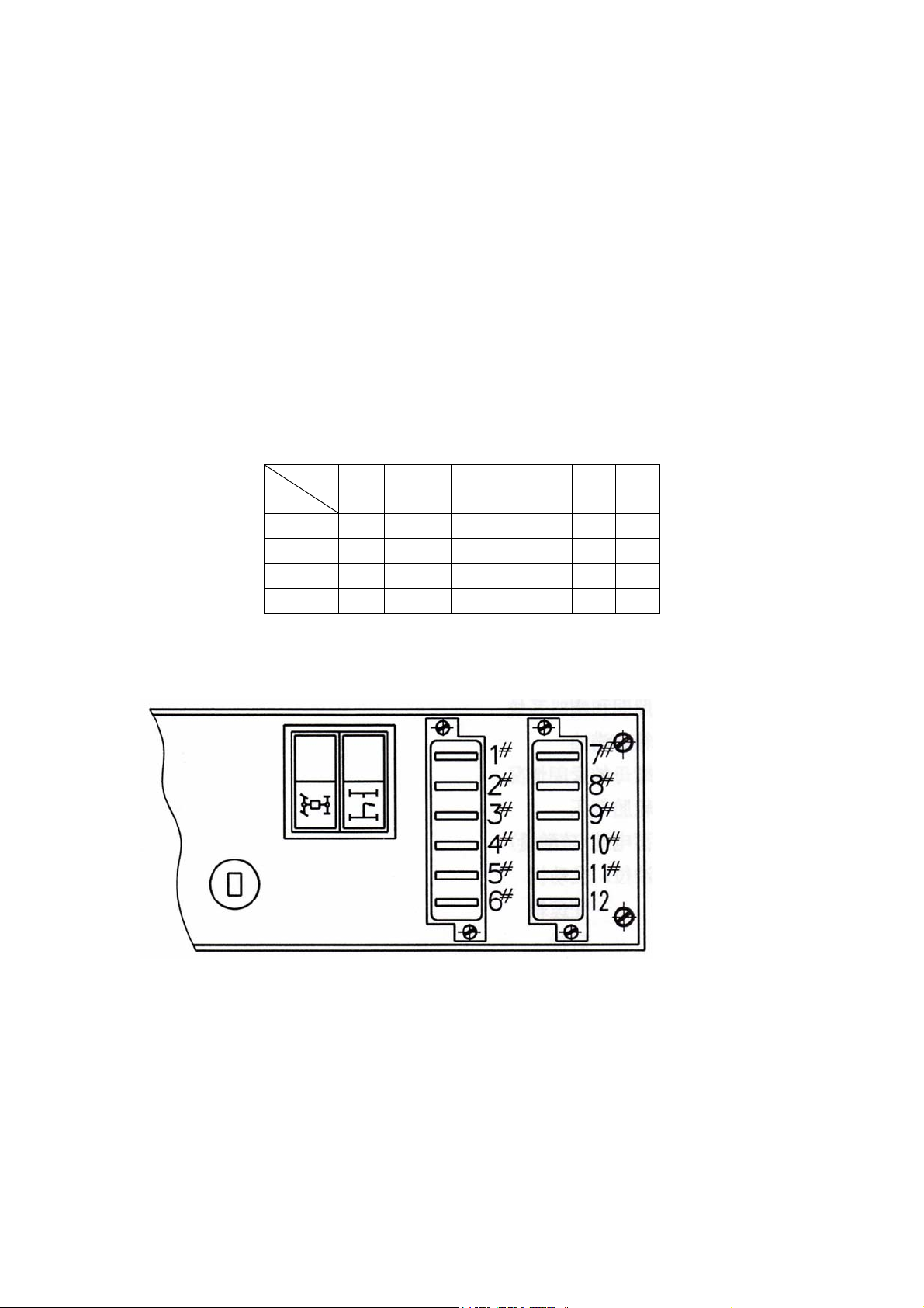
6.1.5 Electrical devices
A. Electrical connection diagram (Fig. 10)
B. Fuse description
ACC
10A
C
20A
R1
50A
R2
50A
1# 10A Oil cut off valve
2# 10A Starting relay
3# 10A Instrument
4# 10A Front and rear wipers,
overhead light
5# 15A Rear working light
6# 15A Front working light
7# 5A Charging relay
15
8# 10A Transmission
9# 20A Steering lamp, brake
light, pilot light and plug
10# 15A Head light
11# 20A Electric horn, magnetic
valve of front axle driving
12# 25A Air conditioning system

7. Operation instruction
7.1 Adjust before operating for the first time
Before unloading the grader, must check whether the machine has been damaged
during transportation. If find out damage, shall contact with the transport company or
commercial agent. The extent of damage or stolen extent shall be recorded on the
freight bill. Contact with the saler and report damage condition to them.They will help
you to repair the machine necessarily and handle your claim against Transport
Company.
The following inspection shall be conducted and the check result shall be
recorded:
a) Lighting and horn systems;
b) The oil levels of oil tank, engine, rear axle, rear balancing tank, rotating
impeller box of blade are in accordance with requirement;
c) Fastening condition of nuts;
d) Whether the tyre pressure is in accordance with regulations and requirement;
e) Whether the battery (sulfuric acid level) has been charged fully;
f) Check liquid levels: Engine
Transmission
Rear axle
Tandem box
Blade rotating turbine box
Hydraulic oil tank
After starting the engine: The working brake pressure signal lamp cannot light,
check the function of the brake and steering systems.
After the machine has worked for more than one week: all grease nipples should
be greased according to the lubrication chart and grease shall be filled.
Antifreezing: Antifreezing diesel oil shall be used if necessary.
7.2 Running-in time
It is recommended that all moving elements of the grader shall be run in, during
this period the grader shall not run under full load.
The grader shall not use full power during the first 50h operating time.
Full power can be used within 50h~100h, while the use time cannot be too long.
7.3 Diagrammatic representation of control instrument and operating lever of
complete machine
16
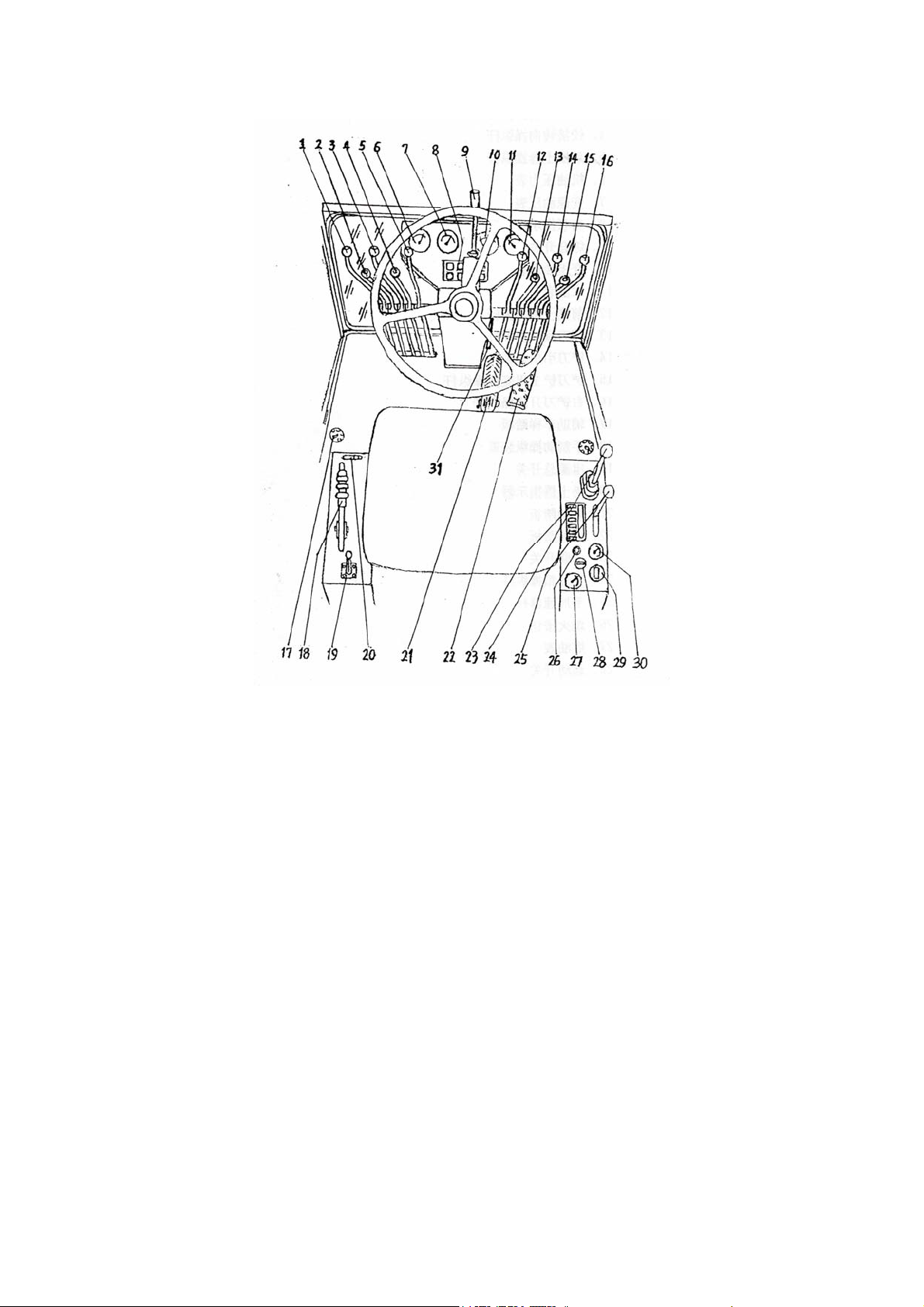
1. Control lever for lifting left blade
2. Control lever for rotating blade
3. Control lever for front wheel lean
4. Control lever for articulated steering
5. Control lever rear scarifier
6. Engine oil pressure gauge
7. Gear change oil pressure gauge
8. Four-gang indicator lamp
9. Comprehensive switch
10. Torque converting oil temperature
gauge
11. Water temperature gauge
12. Control lever for front bulldozing
plate
13. Control lever for front wheel lean
14. Blade outgoing control lever
15. Control lever for blade to scrape
Fig. 11
16. Control lever for lifting right blade
17. pedal of assistant vehicle ladder
18. Control device for hand brake
19. Main power switch
20. Scarifier indicator
21. Brake pedal
22. Accelerator pedal
23. Six-gang switch
24. Control lever for transmission
25. Hand accelerator lever
26. Flameout button
27. Fuel gauge
28. Starting switch
29. Timer
30. Ammeter
31. Lifting lever
17

7.3.1 Switches
1) Mains power switches
Push the handle (Fig. 11/19) of power switch downwards the mains power will
be switched on.
2) Starting switch (See Fig.11/28)
If turn the starting switch by gear clockwise, all power supplies of instruments Ⅰ
will be turned on and turn by gear the engine will be started. If turn back to gear Ⅱ 0
counterclockwise, the engine will be shut down.
7.3.2 Instruments
1) Oil temperature gauge at torque converter outlet (Fig.11 /10)
Measuring range: 40 ~ 140 . Under the normal condition, the temperature shall ℃
be ranged from 80 ~ 110 .Allow instant ℃ rise in temperature, the maximum
temperature is up to 120 .℃
Ammeter (Fig. 11/30)
2)
Measuring range: -40A~ +40A. If pointer points to direction “-”, which means
the battery is discharging; If pointer points to direction “+”, which means the battery
is charging.
3) Water temperature gauge (Fig. 11/11)
Measuring range: 50 ~ 115 . Indicates the cooling ℃ water temperature of engine.
Under normal condition, the water temperature shall be below 90 .℃
4) Timer (Fig. 11/29)
Accumulated range: 0~9999.9h. Accumulated operating time of engine.
5) Transmission control pressure gauge (Fig. 11/7)
Measuring range: 0~2.5MPa. When the oil temperature of transmission is 80~
90 , the variation range of oil pressure of transmission: 1.3~1.5 MPa.℃
The pointer shall always points to above range, if the point is out of this range,
the engine shall be shut down to check and repair faults.
6) Fuel gauge (Fig.11/27)
Measuring range: 0~1. Indicate the oil level in diesel oil tank. Do not start the
machine if there is no oil in oil tank; otherwise, the oil pipe will be blocked and air
enters into this system.
7) Engine oil pressure gauge (Fig.11/6)
Measuring range: 0~1Mpa. The minimum pressure shall not be lower than
0.2Mpa.
7.3.3 Four-gang indicator lamp (Fig. 12)
18
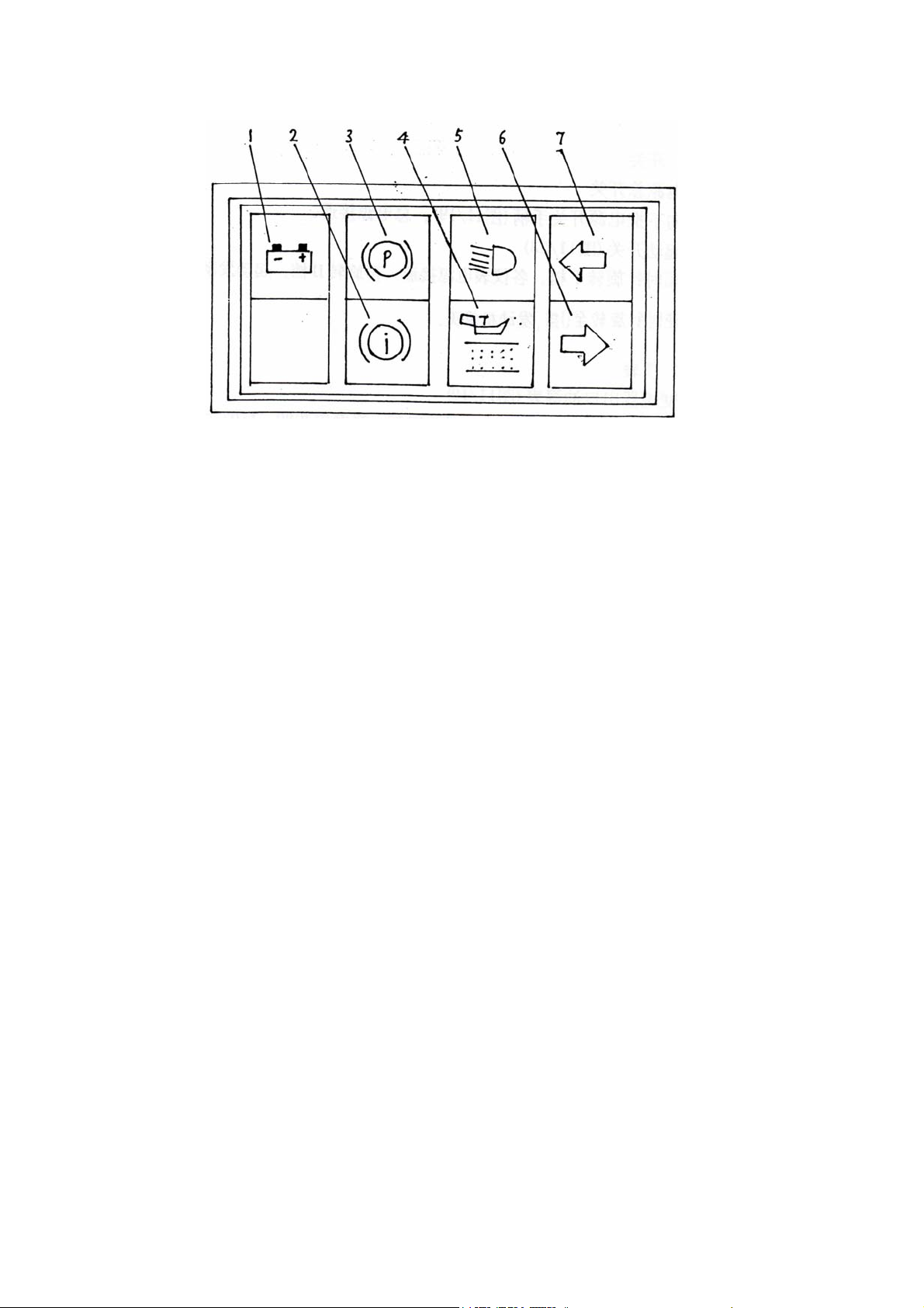
Fig. 12
1) Charge indicator lamp, red (Fig.12/1)
The indicator lamp lights when the engine is running, which means that the
charging line or alternator is at fault or the belt is loosened. The barratry is not
charged, stop the engine and carry on troubleshoot.
2)Indicator lamp for brake service pressure, red (Fig.12/2)
The indicator lamp lights when the engine is running; which means there are
some troubles in the brake system. Stop the grader and engine immediately and carry
out troubleshooting.
3) Indicator lamp for brake, red (Fig.12/11)
The indicator lamp lights in case of service brake.
4) Indicator lamp for hydraulic oil filter, red (Fig.12/4)
The indicator lamp lights when the engine is running; which means that the oil
filters are blocked. Clean or replace the filter element.
5) Indicator lamp for far light, blue (Fig.12/5)
The indicator lamp lights when the front light is switched to far light.
6) Indicator lamp for right turning, green (Fig.12/6)
The indicator lamp lights when steering switch is switched to right turning.
7) Indicator lamp for left turning, green (Fig.12/7)
The indicator lamp is on when the steering switch is switched to left turning.
7.3.4 Six-gang switch (Fig. 13)
19
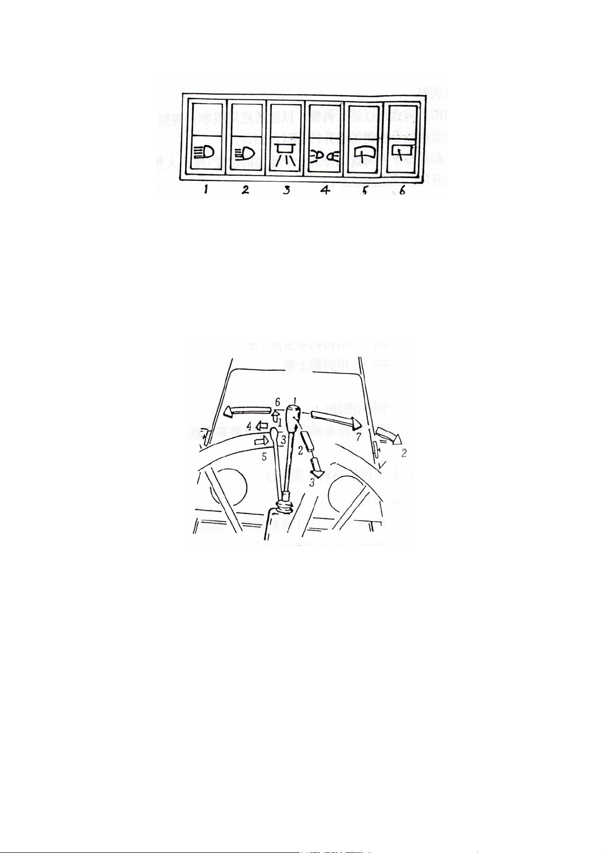
Fig. 13
1. Switch for working light 2. Switch for rear light
3. Overhead light switch in Driver’s cab 4. Switch for pilot light
5. Wiper switch for front window 6. Wiper switch for rear window
7.3.5 Comprehensive switch (Fig. 14)
Fig. 14
Control lever position:
1= Switch off
2= Big head of head lamp
3= Switch off
4= Left turning
5= Right turning
6= Horn
7= Small head of head lamp
7.3.6 Accelerating pedal (Fig. 11/21)
This pedal can be used to control the engine speed.
7.3.7 Brake pedal (Fig. 1 1/22 )
20
 Loading...