

Dings Dynamics Group 90 Series End Mount NEMA 4 User Manual

90 Series
NEMA 4 Enclosure
Brake Instructions
Read carefully before attempting to assemble, install, operate or maintain the product described. Protect yourself
and others by observing all safety information. Failure to comply with instructions could result in personal injury
and/or property damage! Retain instructions for future reference. When unpacking the brake, inspect it carefully
for damage that may have occurred during transit.
Bulletin No. BK4696 (11/13)
4740 WEST ELECTRIC AVENUE l MILWAUKEE, WI 53219
PHONE 414/672-7830 l FAX 414/672-5354
www. dingsbrakes.com
WARNING
Brake performance and features must be carefully matched to the requirements
of the application.
Consideration must be given to torque requirements, especially where an
overhauling condition exists, as well as thermal capacity, ambient temperature,
atmospheric explosion hazards, type of enclosure and any other unusual
conditions.
Improper selection and installation of a brake and/or lack of maintenance may
cause brake failure which could result in damage to property and/or injury to
personnel.
If injury to personnel could be caused by brake failure, additional means must
be provided to insure safety of personnel.
Do not operate manual release or energize brake coil before installation, in
order to preserve prealignment of rotating discs for ease of installation.
DESCRIPTION
This brake is direct acting, electromagnetically released and spring
set. It uses rotating and stationary disc contact to supply positive
braking action. It retains quick release and setting capabilities at all
times.
Simplicity of design has reduced maintenance to an absolute minimum. As with any electromechanical equipment, however, periodic
inspection and adjustment will assure optimum performance. As the
friction disc wears, the magnet gap will increase. The magnet gap
should be check periodically and adjusted when necessary.
SPECIFICATIONS
MOTOR FRAMES - 324TC - 405TC
HOUSINGS - Cast iron.
DUTY - Rated for continuous duty.
VOLTAGES - All standard NEMA voltages and frequencies avail-
able. Other voltages and frequencies are optional.
MOUNTING - Direct to NEMA “C” motor flanges. Adaptors for larger
or smaller frames, foot mounting and vertical mounting are
available.
SHAFTS - NEMA standard length motor shafts and thru shafts may
be used on all models (Cover modification required for thru shafts).
ORDERING INFORMATION
The following data should be furnished with your order for:
REPLACEMENT PARTS
Brake Model Number
Part Number from Tables
Part Description from Tables
(On hub order furnish bore dia. & keyway dimensions. On
electrical parts specify voltage, phase & frequency.)
REPLACEMENT BRAKE
Model Number
Voltage, Phase & Frequency
Hub Bore & Keyway Dimensions
Mounting - Horizontal or Vertical. (If vertical, specify whether above
or below motor. If brake includes foot mounting bracket or adaptor,
specify.
)
Figure 1.
GENERAL SAFETY INFORMATION
NOTE: These brakes are not intended for accurate positioning
applications. They are designed for applications that require rapid
stopping and holding power, such as on conveyors, door openers,
etc.
1. For applications with high inertia-type loads or rapid cycling,
the thermal capacity of the brake must be considered.
2. Observe all local electrical and safety codes, as well as the
National Electrical Code (NEC) and the Occupational Safety
and Health Act (OSHA).
3. Brake motors and brake gearmotors must be securely and
adequately grounded. This can be accomplished by wiring
with a grounded metal-clad raceway system, by using a
separate ground wire connected to the bare metal of the
motor frame, or other suitable means. Refer to NEC Article
250 (Grounding) for additional information. All wiring should
be done by a qualified electrician.
4. Always disconnect power before working on or near a brake
motor, a brake gearmotor, or its connected load. If the power
disconnect point is out of sight, lock it in the open position
and tag it to prevent unexpected application of power.
5. When working on the brake, be sure the load is completely
removed, secured or blocked to prevent injury or property
damage.
6. Provide guarding for all moving parts.
7. Be careful when touching the exterior of an operating motor,
gearmotor or brake. It may be hot enough to cause injury or
to be painful. This condition is normal for modern motors,
which operate at higher temperatures when running at rated
load and voltage.
8. Protect all electrical lead wires and power cables against contact with sharp objects or moving parts.
9. Do not kink electrical lead wires and power cables, and never
allow them to touch oil, grease, hot surfaces or chemicals.
10. Upon usage, the inside surfaces of the brake will contain friction material dust. This dust must be removed before servicing or adjusting the brake. It is important to avoid dispersing
dust into the air or inhaling it, as this may be dangerous to
your health. To avoid dispersing the dust into the air, DO NOT
blow the dust off the brake. Remove dust with a vacuum.
Avoid breathing dust.
Wear a respirator if dust becomes airborne.
INSTALLATION
(See Figures 3 & 4 and Tables 1 & 2)
1. Remove hub (31) from brake and position on motor
shaft with key according to dimension “N”. Stamped
part number on hub should face away from motor.
Tighten hub set screws with 60 lb. ft. torque.
2. Remove cover nuts (21) and cover (19).
3. Place brake on motor, guiding discs on hub.
4. Bolt brake to motor “C” face with four 5/8 inch
socket head cap screws. See Figure 4 for screw
length through bracket.
5. Connect coil leads per appropriate wiring diagram
in Figure 2 and replace cover.
MANUAL RELEASE (See Figure 3)
To operate release, rotate two rods (5) clockwise
until stop screw (17) hits pin. Brake will remain in
released position until rods are manually returned
to original position, or until electrical power is
restored which automatically returns the release
rods to the set position.
TORQUE ADJUSTMENT (See Figures 3 & 4 and Table 2)
Brake is factory set for rated torque per spring length “H”. To increase
stopping time and lower torque, turn four locknuts (9) counterclockwise,
increasing dimension “H”. All four springs must be set to the same length.
Do not decrease spring length “H” as this may cause coil to burn out.
WEAR ADJUSTMENT
(See Figures 3 & 4, Table 2)
Magnet gap “D” increases as friction discs wear. When gap approaches
“D” max., adjust gap to “D” min. dimension by turning nuts (11 and 13).
Magnet gap can vary from nominal + .005” between corners. After setting
gap, readjust torque spring length “H”. Apply 55 lb-ft torque to bottom
jam nuts (11). NOTE: Nut should be black in color.
CAUTION: MAGNET GAP MUST NOT EXCEED “D” MAXIMUM.
FRICTION DISC REPLACEMENT
(See Figures 3 & 4, Table 2)
*When the rotating friction disc (3) wears down to a thickness of 1/4”,
replace disc.
1. Remove cover nuts (21) and cover (19).
2. Unhook loop of torsion springs (10) from pins at rear of magnet plate
(12). Remove release stop screws (17) and shim washers (14 & 15).
3. Remove adjusting lock nuts (11), magnet assembly (12), adjusting
nuts (13), torque nuts (9), washers (8), torque spring (7) and pressure
plate (6).
4. Remove friction disc (3) and stationary disc (4). Replace worn
friction discs.
5. Reassemble all parts in reverse order. Set spring length “H” and
magnet gap “D”. Apply 40 lb-ft torque to bottom jam nuts (11).
Assemble manual release. See “Manual Release Assembly”.
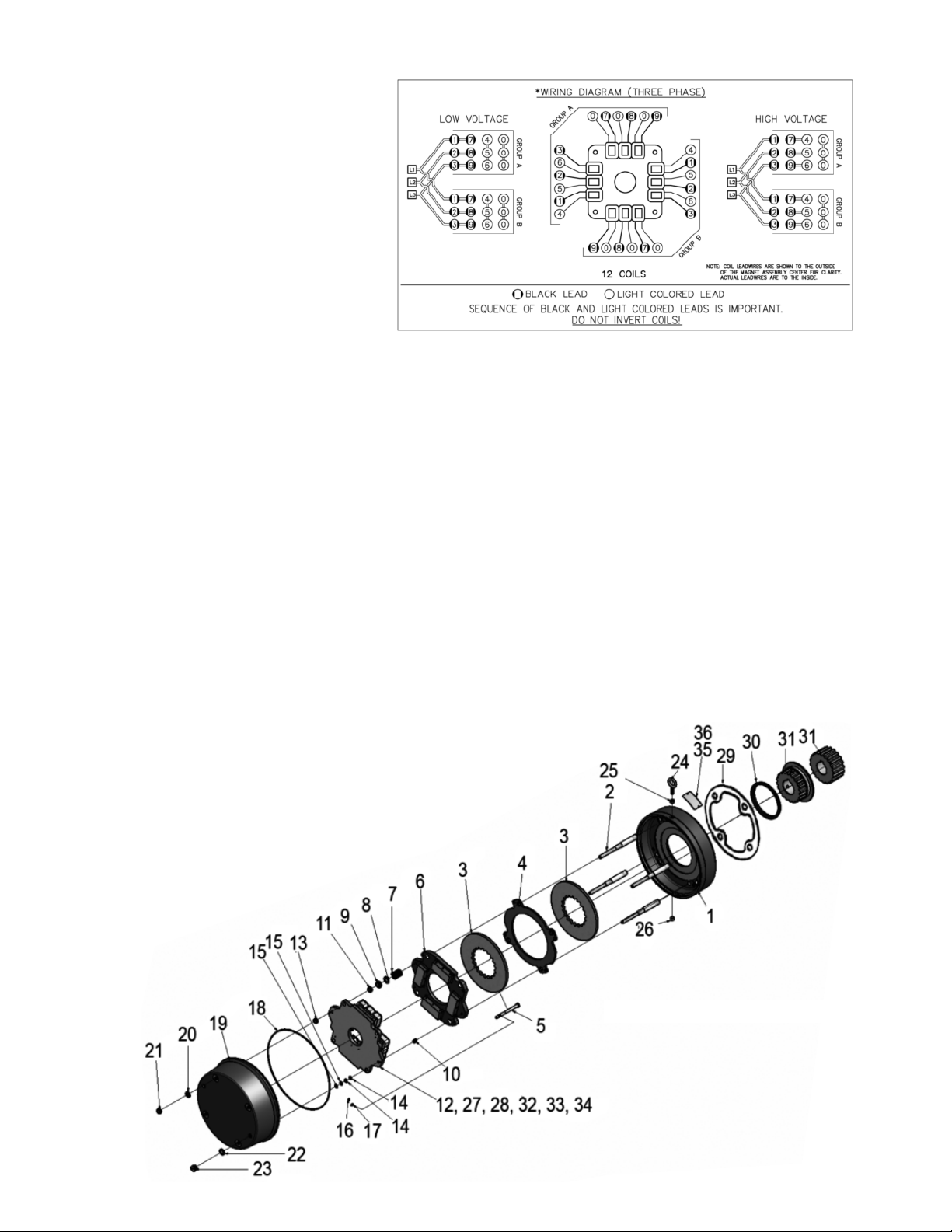
Figure 2. Wiring Diagram
2
Figure 3. Exploded View of Brake
MAGNET COIL REPLACEMENT (See Figures 2 & 3)
Remove magnet assembly (12) as outlined under
FRICTION DISC REPLACEMENT.
Coils are held in place with epoxy cement. Force coil off magnet
mounting plate and remove excess epoxy from all surfaces.
Replacement coils should be held in place with new epoxy cement.
The epoxy cement should be heat resistant and shock resistant.
When installing coils, it is very important to follow EXACTLY the
sequence of black and light colored leads as shown in wiring diagram
(Figure 2). The brake will not operate properly unless coils are all in
the correct position.
MANUAL RELEASE ASSEMBLY (See Figure 3)
When assembling a standard manual release mechanism (Figure 3),
add only enough shim washers (14 & 15) to obtain proper release
action. Too many shim washers will prevent automatic reset when
electrical power is applied. Too few washers will prevent the motor
shaft from turning freely. Replace stop screws (17). Wind each torsion
spring (10) approximately 1/4 turn and hook spring loop over pin.
 Loading...