

Dings Dynamics Group 90 Series End Mount - 450 lb-ft NEMA 4 User Manual
90 Series
Brake
Instructions
Read carefully before attempting to assemble, install, operate or maintain the product described. Protect yourself
and others by observing all safety information. Failure to comply with instructions could result in personal injury
and/or property damage! Retain instructions for future reference. When unpacking the brake, inspect it carefully
for damage that may have occurred during transit.
Bulletin No. BK4690 (8/02)
4740 WEST ELECTRIC AVENUE MILWAUKEE, WI 53219 PHONE 414/672-7830 FAX 414/672-5354 www. dingsco.com
DESCRIPTION
The 90 Series Brake is a spring set, electro magnetically released unit.
Heavy duty friction discs are standard and consist of non-asbestos
friction material bonded to an aluminum carrier. An automatic reset
manual release is standard (deadman release optional).
SPECIFICATIONS
MOTOR FRAMES - 324TC, 326TC, 364TC, 365TC, 404TC, 405TC
HOUSINGS - Cast iron.
DUTY - Rated for continuous duty.
VOLTAGES - All standard NEMA voltages and frequencies available.
Other voltages and frequencies are optional.
MOUNTING - Direct to NEMA “C” motor flanges. Adaptors for larger
or smaller frames, foot mounting and vertical mounting are available.
BRAKE OPERATION
Refer to Figure 3.
During brake setting, rotating discs (5), stationary discs (6), and the
pressure plate (7) are forced against the bracket (1) by the torque
springs (53) and (54), transmitted through the shock absorbers (46).
The friction developed between the discs is transmitted through the
rotating discs and hub (3) to the motor shaft as torque. When the
magnet coils are energized, the magnetic field generated attracts the
pressure plate; the rotating discs, hub and shaft are then free to turn.
As the friction discs wear, the magnet gap will increase. The magnet
gap should be checked periodically and adjusted when necessary.
MANUAL RELEASE OPERATION
Refer to Figure 3.
1. AUTOMATIC
-
Turning the release knob (9) clockwise until it
stops, will release the brake. It will remain in the released position
until the knob is manually returned to its original position, or until
magnet coils are energized which automatically returns the knob to
its original position. NOTE: Due to the size of the discs, a slight drag
is common (5-7 lb. ft.).
2. DEADMAN
-
Turning the release knob (9) clockwise until it
stops, will release the brake. Knob will immediately return to its
original position when the turning force is removed. NOTE: Due to
the size of the discs, a slight drag is common (5-7 lb. ft.).
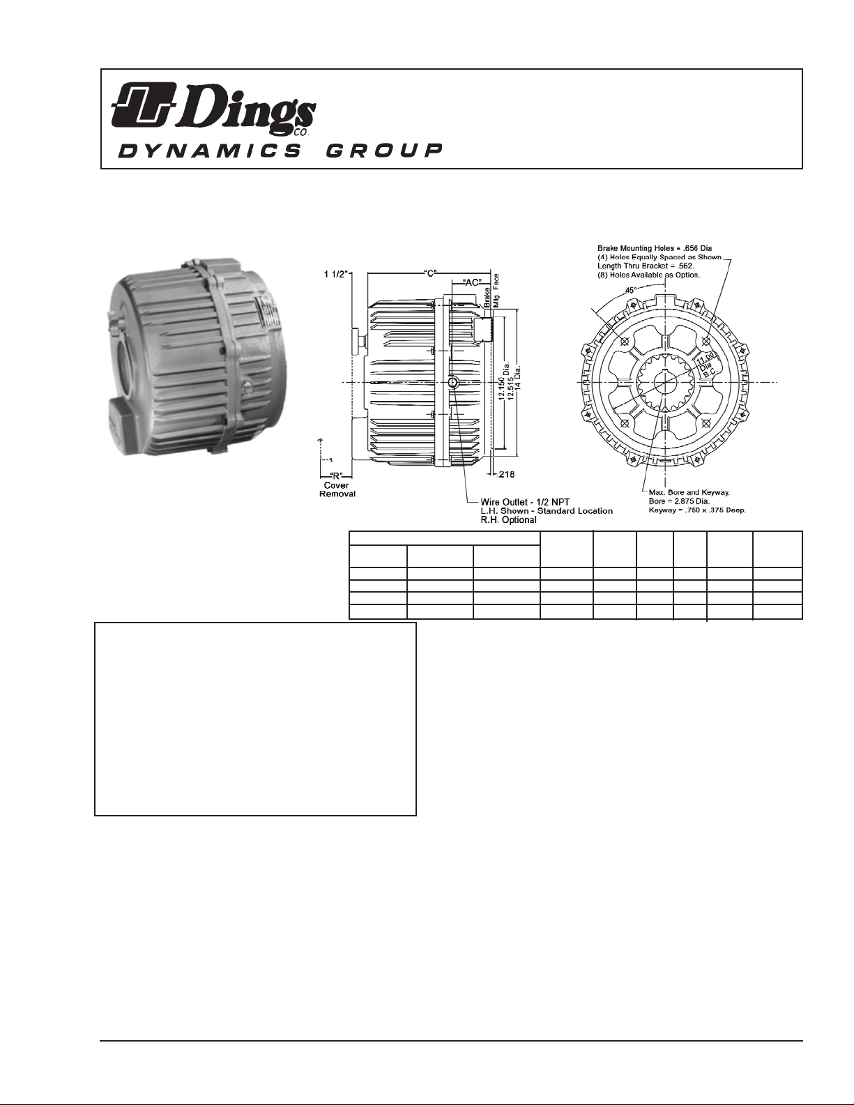
Figure 1.
WARNING
Brake performance and features must be carefully matched to
the requirements of the application.
Consideration must be given to torque requirements, especially
where an overhauling condition exists, as well as thermal
capacity, ambient temperature, atmospheric explosion hazards,
type of enclosure and any other unusual conditions.
Improper selection and installation of a brake and/or lack of
maintenance may cause brake failure which could result in
damage to property and/or injury to personnel.
If injury to personnel could be caused by brake failure, additional
means must be provided to insure safety of personnel.
MODEL NO. INERTIA
STD. ENCL. SEVERE TORQUE WK
2
WEIGHT
HSG. HSG. DUTY HSG. LB. FT. C R AC LB. FT.
2
LBS.
2-92180-30 4-92180-31 6-92180-32 180 10 3/8 6 3/4 2.53 1.00 195
2-93270-30 4-93270-31 6-93270-32 270 10 3/8 7 1/2 2.53 1.38 205
2-94360-30 4-94360-31 6-94360-32 360 11 1/2 7 1/8 3.65 1.84 240
2-95450-30 4-95450-31 6-95450-32 450 11 1/2 7 7/8 3.65 2.30 250
INSTALLATION
(Refer to Figures 2, 3, 4 & 5)
1. STANDARD HOUSING
-
Install hub (3) onto motor shaft with key
per dimension “N” as shown in Figure 3. Hub part number should face
away from motor. Tight hub set screws with 20 ft. lb. of torque.
2. ENCLOSED HOUSING
-
Slide seal ring (61) onto motor shaft
as shown in Figure 3. Install hub (3) onto motor shaft with key per
dimension “N” as shown in Figure 3. Hub part number should face
away from motor. Butt seal ring (61) against hub, and tighten set
screws in both hub and seal ring with 20 ft. lbs. of torque. Apply a
small amount of grease to O.D. of seal ring. CAUTION: Excessive
grease could work its way onto the rotating disc causing loss of
torque.
3. DISASSEMBLY
-
Disassemble brake by removing cover screws
(14), lockwashers (13), cover (8), locknuts (16), operator assembly (60),
jam nuts (15), pressure plate (17), rotating discs (5), and stationary
discs (6).
4. REASSEMBLY
-
Mount bracket (1) (with mounting gasket (59)
when used) onto motor using 5/8-11 hex socket head screws. Be
sure wire outlet location is correct. Install rotating discs (5), stationary
discs (6), and pressure plate assembly (7) in the order shown in Figure
3. NOTE: All numbers and letters to be facing towards you during
assembly. The stamped “O” on the hub tooth should line up with the
stamped number on the tooth space of the rotating disc. The stamped
number on the stationary discs and stamped letter “P” on the pressure
plate should be towards the top of the brake. (See Figure 5.) Install
jam nuts (15) approximately 1 1/2” from end of studs (2). Washer face
on jam nuts to face towards you. Place operator assembly (60), with
release shaft at top, onto brake over the studs. Install locknuts (16)
on end of studs only. Block operator arm (35) to insure proper air gap
setting. (See Figure 4.) To block operator arm: push at point “X”, then
place an object between the operator arm and the magnet plate. Be
sure not to place the object against the manual release. Push the
operator assembly forward until it is flush with the pressure plate at the
magnet faces. If the operator arm is properly blocked the magnet faces
will be flush and the two shock absorbers (46) will be free to move
back and forth. Again push operator assembly towards motor to take
up all clearances.
5. MAGNET ADJUSTMENT
-
Adjust air gap “A” between locknuts
and magnet plate face using a spacer equal to air gap “A” nominal per
appropriate model, refer to Figure 3. Then pull the magnet plate back
against all eight locknuts (16). Bring the jam nuts (15) back to magnet
plate and tighten evenly. Remove object blocking operator arm. Check
air gap after removing block. Readjust if necessary. Connect lead wires
per wiring diagram as shown in Figure 2. APply rated voltage to brake.
If there is a loud magnet noise, find the area of heavy vibration by
placing a finger on each end of the four magnets in the area where it
meets the pressure plate. Using nuts (15) and (16), on the stud (2)
closest to the vibration, move magnet plate in and out, by loosening
one nut and tightening the other, 1.8 turn maximum,. Adjust in and out
until magnet noise is reduced. Continue this process around all eight
studs if needed, until magnet noise is at a minimum.
6. COVER INSTALLATION
-
Install cover (8) (with gasket (58) when
used) making sure pin in release handle (9) is facing up for proper
alignment with release shaft, add cover screws (14) with lockwashers
(13).
TORQUE ADJUSTMENT
(Refer to Figure 3.)
Torque springs (53) and (54) are installed at the factory per dimension
shown, 1 1/6”. (See Figure 3.) This setting will give the rated torque for
all models. To reduce torque (which will increase stopping time),
increase installed setting. The maximum setting is 1 7/16”. This will
reduce torque by 20%. To do this, first loosen locknut (16), then bring
the torque adjusting screw (41) out to the desired length. Then while
holding the adjusting screw in place, tighten locknut (16). IMPORTANT:
Do not decrease spring length, as this may cause coils to burn out.
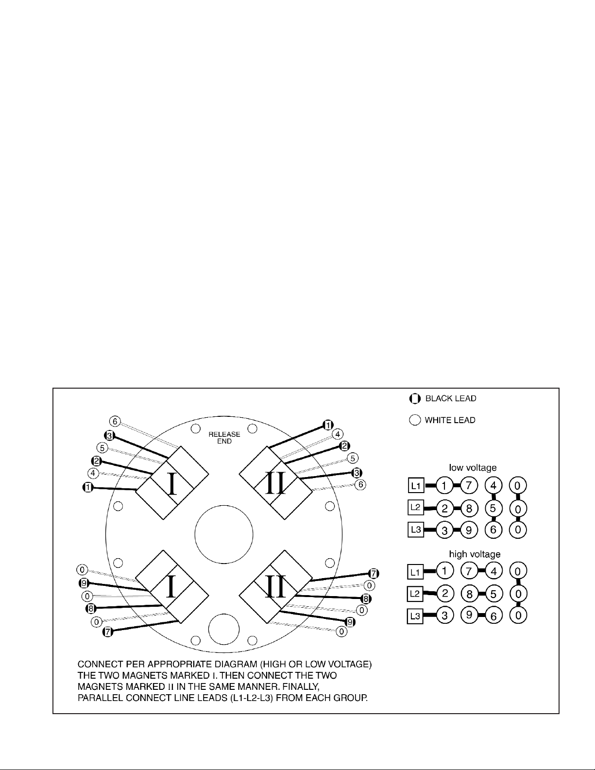
Figure 2.Wiring Diagram
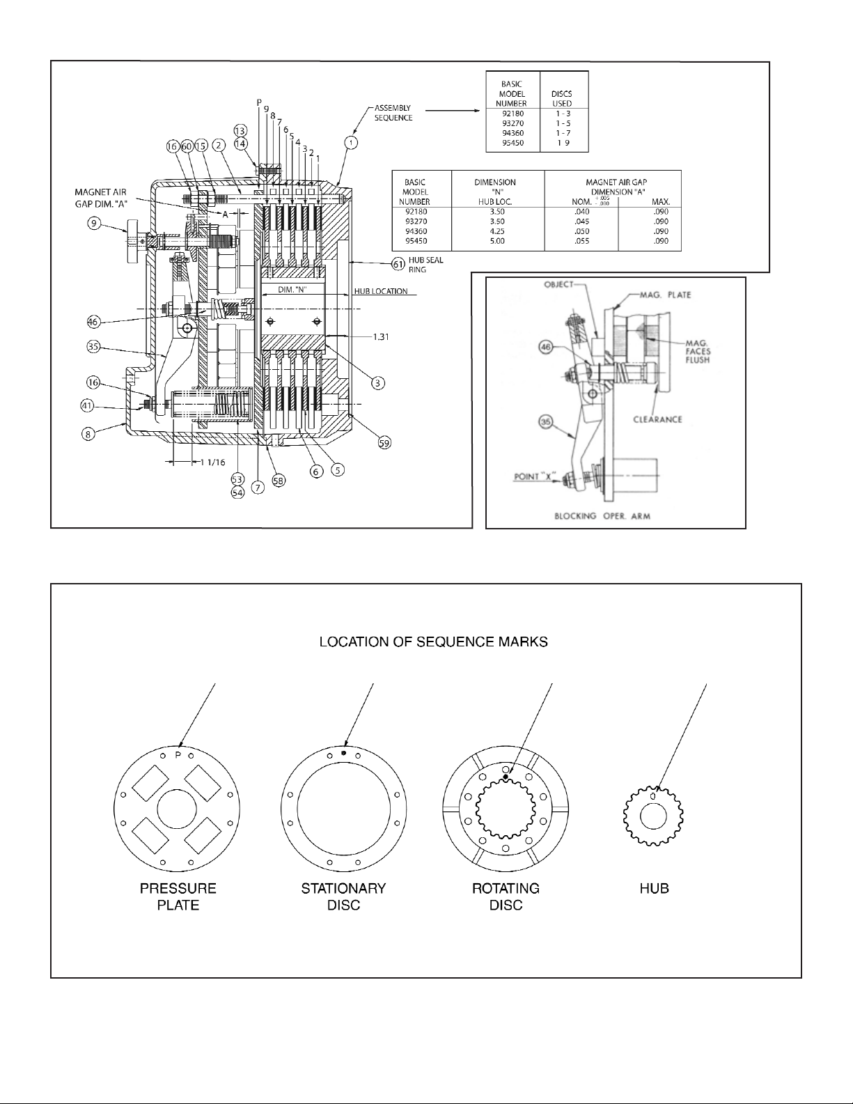
Figure 3.
Figure 4.
Figure 5.
 Loading...