

Dings Dynamics Group 70 Series End Mount NEMA 2 Standard User Manual
70 Series
2 Post NEMA 2 Enclosure
Brake Instructions
Read carefully before attempting to assemble, install, operate or maintain the product described. Protect yourself
and others by observing all safety information. Failure to comply with instructions could result in personal injury
and/or property damage! Retain instructions for future reference. When unpacking the brake, inspect it carefully
for damage that may have occurred during transit.
Bulletin No. BK4703 (4/11)
4740 WEST ELECTRIC AVENUE MILWAUKEE, WI 53219 PHONE 414/672-7830 FAX 414/672-5354 www.dingsbrakes.com
WARNING
Brake performance and features must be carefully matched to the
requirements of the application.
Consideration must be given to torque requirements, especially where
an overhauling condition exists, as well as thermal capacity, ambient
temperature, atmospheric explosion hazards, type of enclosure and any
other unusual conditions.
Improper selection and installation of a brake and/or lack of maintenance
may cause brake failure which could result in damage to property and/or
injury to personnel.
If injury to personnel could be caused by brake failure, additional means
must be provided to insure safety of personnel.
Do not operate manual release or energize brake coil before installation,
in order to preserve prealignment of rotating discs for ease of installation.
DESCRIPTION
This brake is direct acting, electromagnetically released and spring set.
It uses rotating and stationary disc contact to supply positive braking
action. It retains quick release and setting capabilities at all times.
Simplicity of design has reduced maintenance to an absolute minimum.
As with any electromechanical equipment, however, periodic inspection
and adjustment will assure optimum performance. As the friction disc
wears, the magnet gap will increase. The magnet gap should be check
periodically and adjusted when necessary.
SPECIFICATIONS
MOTOR FRAMES - 182TC, 184TC, 213TC, 215TC, 254TC, 256TC.
HOUSINGS - Cast iron and steel.
DUTY - Rated for continuous duty.
VOLTAGES - All standard NEMA voltages and frequencies available.
Other voltages and frequencies are optional.
MOUNTING - Direct to NEMA “C” motor flanges. Adaptors for larger or
smaller frames, foot mounting and vertical mounting are available.
SHAFTS - NEMA standard length motor shafts and thru shafts may be
used on all models except units with Mark II Release (Cover modification
required for thru shafts).
ORDERING INFORMATION
The following data should be furnished with your order for:
REPLACEMENT PARTS
Brake Model Number
Part Number from Tables
Part Description from Tables
(On hub order furnish bore dia. & keyway dimensions. On
electrical parts specify voltage, phase & frequency.)
REPLACEMENT BRAKE
Model Number
Voltage, Phase & Frequency
Hub Bore & Keyway Dimensions
Mounting - Horizontal or Vertical. (If vertical, specify whether above or
below motor. If brake includes foot mounting bracket or adaptor, specify.
)
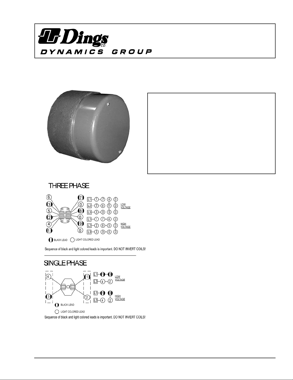
Figure 1.
Figure 2.Wiring Diagram
G070796-001
INSTALLATION
(See Figures 3 & 5, Tables 1 & 2)
1. Remove hub (22) from brake and position on motor shaft with key
according to dimension “N”. Stamped part number on hub should
face away from motor. Tighten hub set screws with 12 lb. ft. torque.
2. Remove cover screws (17) and cover (18).
3. Place brake on motor, guiding discs on hub.
4. Bolt brake to motor “C” face with four 1/2 inch socket head cap
screws. See Figure 5 for screw length thru bracket.
5. Connect coil leads per appropriate wiring diagram in Figure 2 and
replace cover.
MANUAL RELEASE
(See Figure 3)
To operate release, rotate two rods(7) clockwise until stop screw
(9) hits pin. Brake will remain in released position until rods are
manually returned to original position, or until electrical power is
restored which automatically returns the release rods to the set
position.
TORQUE ADJUSTMENT
(See Figures 3 & 5)
Brake is factory set for rated torque per spring length “H”. To increase
stopping time and lower torque, turn two locknuts (13) counterclockwise, increasing dimension “H”. All two springs must be set to the
same length. Do not decrease spring length “H” as this may cause coil
to burn out.
WEAR ADJUSTMENT
(See Figures 3 & 5, Table 2)
Magnet gap “D” increases as friction discs wear. When gap approaches
“D” max., adjust gap to “D” min. dimension by turning nuts (15 and 20).
Magnet gap can vary from nominal + .005” between corners. After
setting gap, readjust torque spring length “H”.
CAUTION: MAGNET GAP MUST NOT EXCEED
“D” MAXIMUM.
FRICTION DISC REPLACEMENT
(See Figures 3 & 5, Table 2)
*When the rotating friction disc (3) wears down to a thickness of 7/32”,
replace disc.
1. Remove cover screws (17) and cover (18).
2. Unhook loop of torsion springs (8) from pins at rear of magnet
plate (29). Remove release stop screws (9), washers (12) and
shims (11).
3. Remove adjusting lock nuts (20), magnet assembly (29), adjusting
nuts (15), torque nuts (13), washers (14), torque spring (5) and
pressure plate (28).
4. Remove friction disc (3) and stationary disc (4). Replace worn
friction discs.
5. Reassemble all parts in reverse order. Set spring length “H”
and magnet gap “D”. Assemble manual release. See following
paragraph.
MANUAL RELEASE ASSEMBLY
(See Figure 3)
When assembling a standard manual release mechanism (Figure 3),
add only enough shim washers (11) to obtain proper release action.
Too many shim washers will prevent automatic reset when electrical
power is applied. Too few washers will prevent the motor shaft from
turning freely. Replace stop screws (9). Wind each torsion spring (8)
approximately 1/4 turn and hook spring loop over pin.
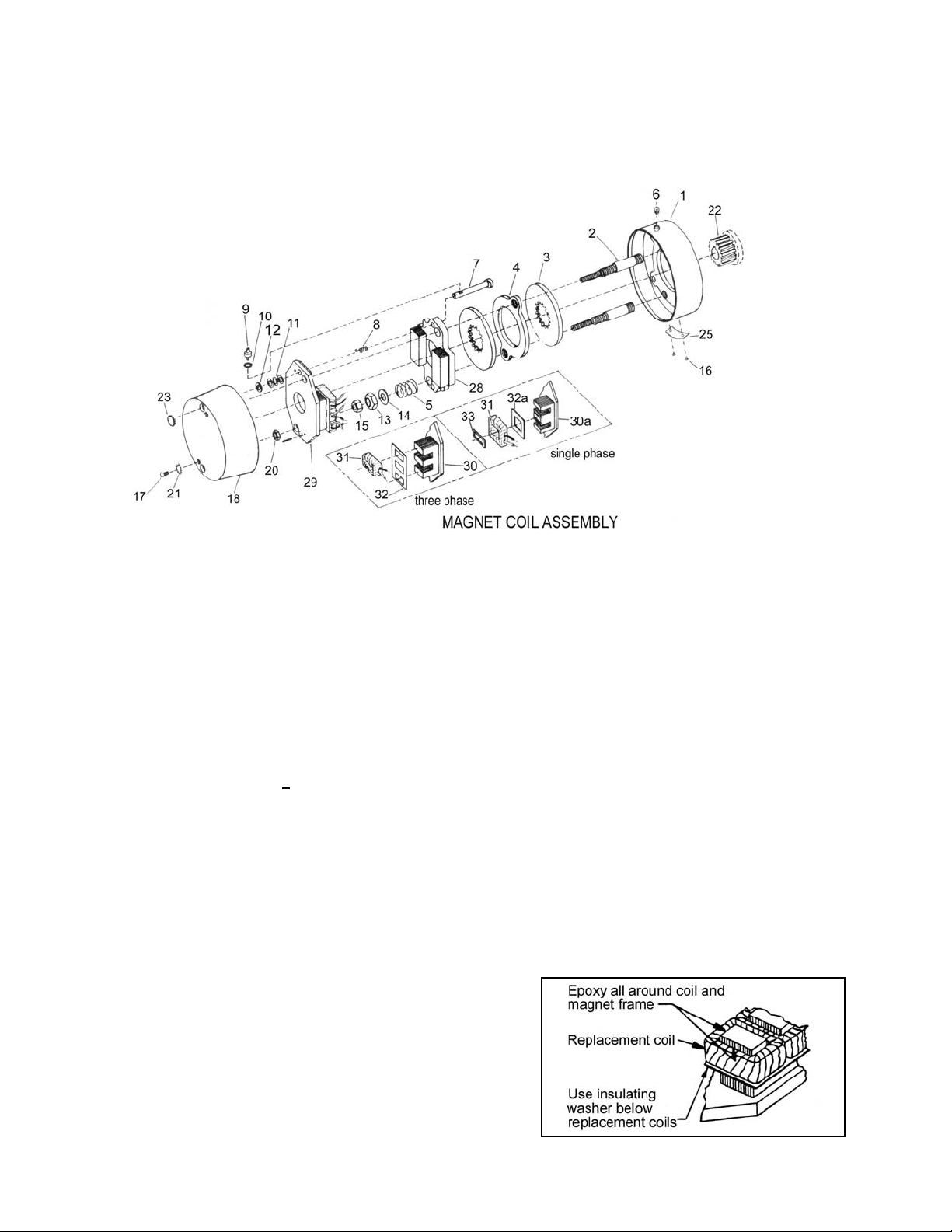
MAGNET COIL REPLACEMENT
(See Figures 3 & 4)
Remove magnet assembly as outlined under FRICTION DISC
REPLACEMENT.
Coils (31) are held in place with epoxy cement. Force coil off magnet
mounting plate and remove excess epoxy from all surfaces.
Replacement coils should be held in place with new epoxy cement.
The epoxy cement should be heat resistant and shock resistant.
Place an insulating washer (32 or 32a) below the coils. Order insulating
washers when ordering coils. An insulating washer can be cut to suit
when replacing only one coil on a multiple coil assembly.
When installing coils, it is very important to follow EXACTLY the
sequence of black and light colored leads as shown in wiring diagram
(Figure 2). The brake will not operate properly unless coils are all in
the correct position.
Figure 4. Fastening of Replacement Magnet Coils
Figure 3. Exploded View of Brake
 Loading...