

Dings Dynamics Group 60 Series End Mount NEMA 4X User Manual
60 Series End-Mount
Brake Instructions
NEMA 4 & NEMA 4X Enclosure
Bulletin No. BK4660 (8/07)
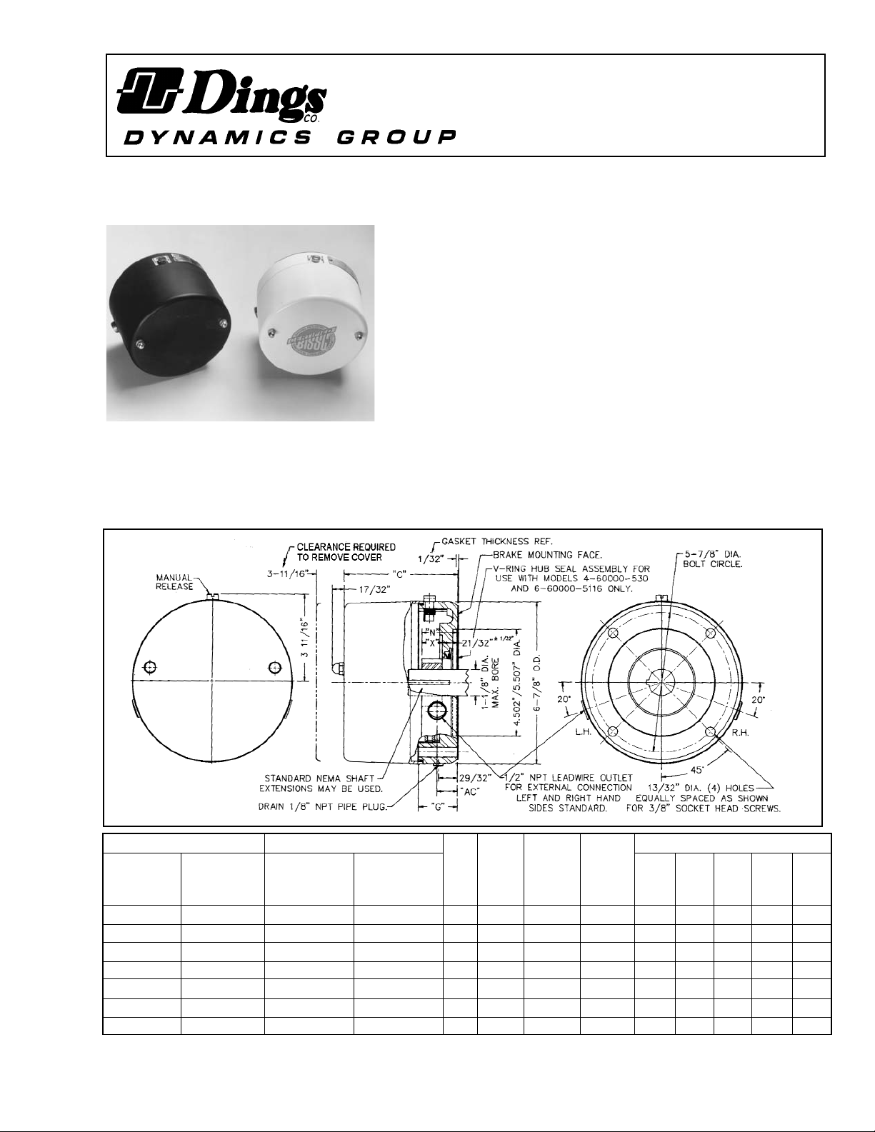
DESCRIPTION
These magnetic disc brakes are direct acting, electromagnetically released
and spring set. They use rotating friction and stationary disc contact to
supply positive brakeing action. They mount directly onto NEMA 56C,
143TC, and 145TC frame motors, on the end opposite the drive shaft.
Models 6-60000-543 and 6-60000-5115 are mounted directly to a motor
where a gasket between the brake and motor face prevents liquid media
from enering the brake.
Models 4-60000-530 and 6-60000-5116 are for TEFC motors or foot
mounting applications; brake design with hub seal prevents liquid media
from entering the brake through opeings in the motor fan cover or foot
mounting bracket.
Models 6-60000-543 and 4-60000-530 are standard end-mount series
NEMA 4 Enclosure.
Models 6-60000-5116 and 6-60000-5115 are washdown NEMA 4X endmount series (BISSC Std. #29).
WARNING: Do not install or use these brakes in
an explosive atmosphere.
Figure 1
4740 W. Electric Avenue Milwaukee, WI 53219 414/672-7830 FAX 414/672-5354 www. dingsco.com
Read carefully before attempting to assemble, install, operate or maintain the product described. Protect yourself
and others by observing all safety information. Failure to comply with instructions could result in personal injury
and/or property damage! Retain instructions for future reference.
*Thermal capacity (HPS/MIN.) was determined under the following test conditions: a) Room temperature 72oF. b) Stopping time of one second or less.
c) Brake mounted in a horizontal position. d) Equal on and off times. e) 1800 RPM f) Coil energized with 110% of rated voltage.
**G Length of mounting hole through bracket
NEMA 4
NEMA 4X
NEMA 4 NEMA 4X
No.
of
Discs
Torque
Lb.Ft.
Thermal
Capacity
HPS/MIN*
Inertia of
Rotating
Parts
Lb.Ft.
2
Dimensions
Standard with hub seal Standard with hub seal C AC G** X N
6-61001-543 4-61001-530 6-61001-5115 6-61001-5116 1 1.5 6 .006 4.812 .937 1.625 .875 1.531
6-61003-543 4-61003-530 6-61003-5115 6-61003-5116 1 3 6 .006 4.812 .937 1.625 .875 1.531
6-62006-543 4-62006-530 6-62006-5115 6-62006-5116 2 6 6 .011 4.812 .937 1.625 .875 1.531
6-62010-543 4-62010-530 6-62010-5115 6-62010-5116 2 10 6 .011 4.812 .937 1.625 .875 1.531
6-63015-543 4-63015-530 6-63015-5115 6-63015-5116 3 15 6 .017 5.125 1.250 1.937 1.187 1.844
6-63020-543 4-63020-530 6-63020-5115 6-63020-5116 3 20 6 .017 5.125 1.250 1.937 1.187 1.844
6-64025-543 4-64025-530 6-64025-5115 6-64025-5116 4 25 6 .022 5.437 1.562 2.250 1.343 2.000
WARNING:
Brake performance and features must be carefully
matched to the requirements of the application.
Consideration must be given to torque requirements,
especially where an overhauling condition exists, as well
as thermal capacity, ambient temperature,
atmospheric explosion hazards, type of enclosure and
any other unusual conditions.
Improper selection and installation of a brake and/or lack
of maintenance may cause brake failure which could
result in damage to property and/or injury to
personnel.
If injury to personnel could be caused by brake failure,
additional means must be provided to insure safety of
personnel.
UNPACKING
When unpacking the brake, inspect it carefully for damage
that may have occurred during transit.
GENERAL SAFETY INFORMATION
NOTE: These brakes are not intended for accurate
positioning applications. They are designed for applications
that require rapid stopping and holding power, such as on
conveyors, door openers, etc.
1. For applications with high inertia-type loads or rapid
cycling, the thermal capacity of the brake must be
considered.
2. Observe all local electrical and safety codes, as well
as the National Electrical Code (NEC) and the
Occupational Safety and Health Act (OSHA).
3. Brake motors and brake gearmotors must be
securely and adequately grounded. This can be
accomplished by wiring with a grounded metal-clad
raceway system, by using a separate ground wire
connected to the bare metal of the motor frame, or
other suitable means. Refer to NEC Article 250
(Grounding) for additional information. All wiring
should be done by a qualified electrician.
4. Always disconnect power before working on or near
a brake motor, a brake gearmotor, or its connected
load. If the power disconnect point is out of sight,
lock it in the open position and tag it to prevent
unexpected application of power.
5. When working on the brake, be sure the load is
completely removed, secured or blocked to prevent
injury or property damage.
6. Provide guarding for all moving parts.
7. Be careful when touching the exterior of an operating
motor, gearmotor or brake. It may be hot enough
to cause injury or to be painful. This condition is
normal for modern motors, which operate at higher
temperatures when running at rated load and
voltage.
8. Protect all electrical lead wires and power cables
against contact with sharp objects or moving parts.
9. Do not kink electrical lead wires and power cables,
and never allow them to touch oil, grease, hot
surfaces, or chemicals.
2
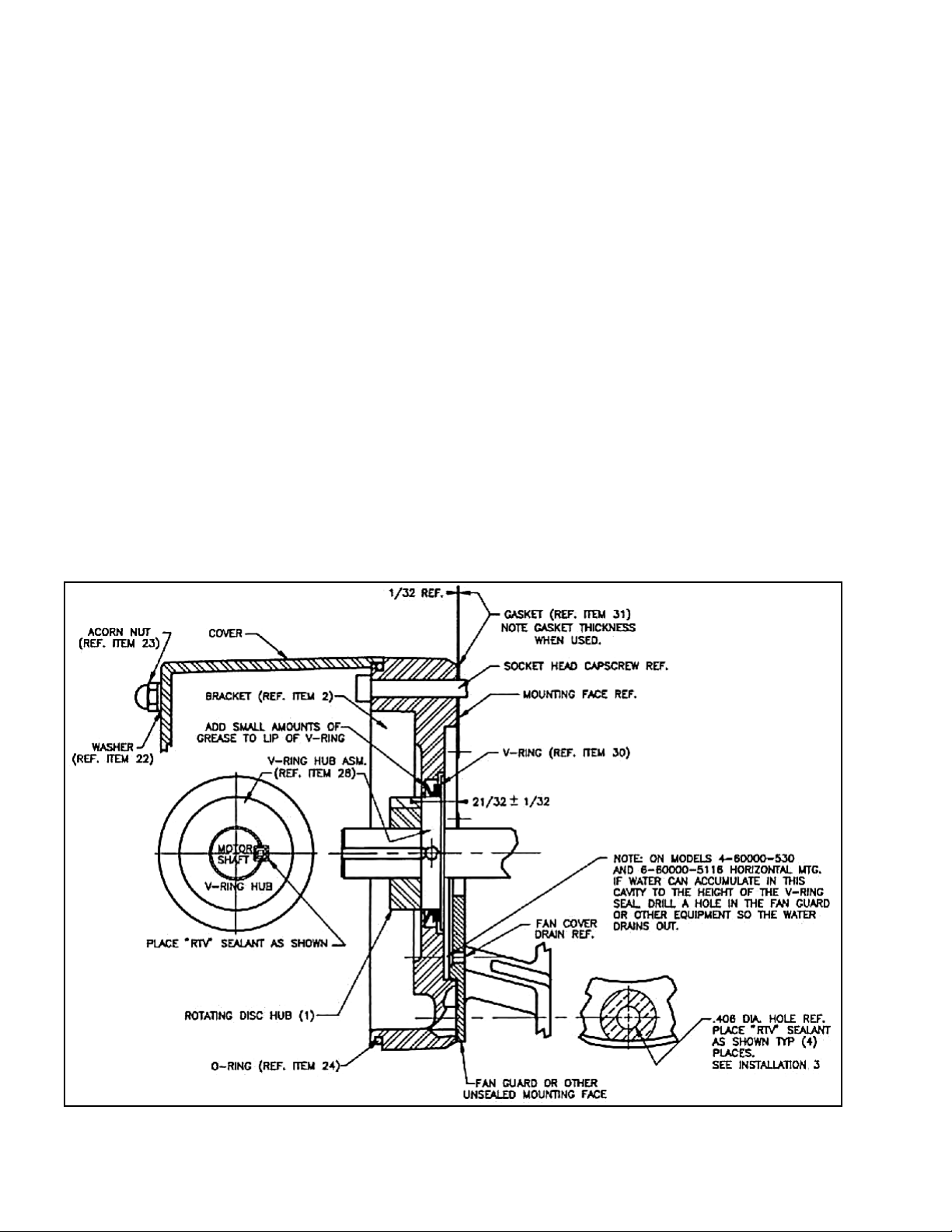
Figure 2
3
INSTALLATION
CAUTION: To preserve pre-alignment of rotating discs for
ease of installation, do not operate manual release or
energize brake coil before installation.
NOTE: The brakes are designed for horizontal mounting.
Modification is required for vertical mounting. Brakes that are
modified will have a prefix on the model number of VO
(Vertical Over) or VU (Vertical Under).
Numbers in parentheses refer to parts illustrated in Figs. 2, 4
and 10.
Mounting Hub on Motor Shaft
For models 6-60000-543 and 6-60000-5115:
1. Place rotating disc hub (1), with key, onto motor shaft
with part number facing away from motor to dimension shown in Fig. 2 (
21
/32 ± 1/32). Measure from brake
mounting face as shown.
For models 6-60000-530 and 6-60000-5116:
1. Remove V-ring (30) from V-ring hub assembly (28).
2. Place V-ring hub assembly (28) onto motor shaft with
part number facing away from motor to dimension
shown in Fig. 2 (
21
/32 ± 1/32).
NOTE: If motor shaft keyway extends into V-ring area,
install a key long enough to engage V-ring hub assembly
(28) and rotating disc hub (1). See Step 3 before tighten
ing setscrews. Tighten both setscrews to 35 lb. in. torque.
3. Place RTV sealant as shown (small amount to fill
crevices between V-ring hub assembly (.040” x 45°
chamfer), motor shaft, hub keyway and motor shaft
keyway. Use Dow Corning #739 RTV only; other
types may form acetic acid during curing if subjected
to water or high humidity. This will cause premature
failure of zinc plated parts.
CAUTION: If this proecedure is bypassed, liquid
media may seep into the brakes.
4. Replace V-ring (30) onto V-ring hub assembly as
shown in Fig. 2. Apply a small amount of grease to lip
of V-ring.
5. Place rotating disc hub (1) with key if not already in
place, onto motor shaft with part number facing away
from motor to dimension shown in Fig. 2 (
21
/
32 ±
1
/
32).
Rotating disc hub will butt against the V-ring hub as
shown.
6. Tighten both setscrews to 6 - 8 lb.ft. torque.
Placing Brake on Motor Shaft
1. Remove acorn nuts (23), washers (22), and cover (20).
Place brake on motor mounting face aligning hub
splines into brake disc splines. Make sure gasket (31)
is in place. Drain plug (25) to face down on horizontal
models.
NOTE: for models 4-60000-530 and 6-60000-5116 only: If
gasket (31) does not make contact around mounting face
totally (360°), exclude gasket (31) and place RTV sealant
around mounting bolt holes to approximately 1” dia. as
shown in Fig. 2. Use Dow Corning #739 RTV only; other
types may form acetic acid during curing if subjected to
water or high humidity. This will cause premature failure of
zinc plated parts.
If tapped holes in motor for mounting bolts are not totally
enclosed, place RTV sealant around threads before bolting
brake to motor. Use Dow Corning #739 RTV ony; other types
may form acetic acid during curing if subjeted to water or high
humidity. This will cause premature failure of zinc plated parts.
You may have to add drain in fan guard or other equipment as
shown in Fig. 2.
2. Tighten mounting bolts to 25 lb. ft. torque
3. Connect coil leads as outlined under “Connection of Coil
Leads” and Fig. 3.
4. Let RTV #739 cure 24 hours before replacing cover.
5. Replace cover (20) and fasten with three acorn nuts (23)
and washers (22). Tighten nuts to 5 lb. ft. torque.
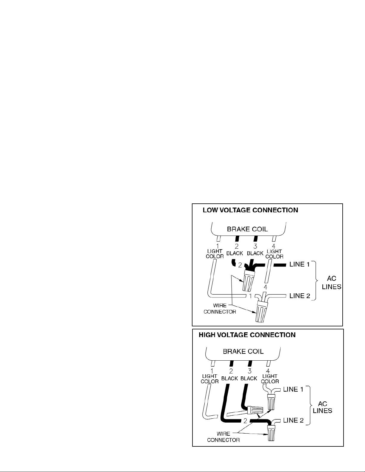
Connection of Coil Leads
After securing the brake to the motor, connect coil leads for
proper voltage per wiring diagram (Fig. 3 shows dual voltage
coil). Incorrect connection can result in brake failure.
CAUTION: The voltage supplied to the coil must match the
voltage that the coils are connected for, or the coils will
burn out.
Single voltage coil: Connect brake coil leads to any two line
leads (single or three phase) of same voltage and frequency
as brake.
Dual voltage coil: Connect leads 2 and 4 to any two motor line
leads (single or three phase) of same voltage as brake.
Connect leads 1 and 3 as shown for voltage desired. Brake
must be energized with motor.
Figure 3
Wiring Diagrams
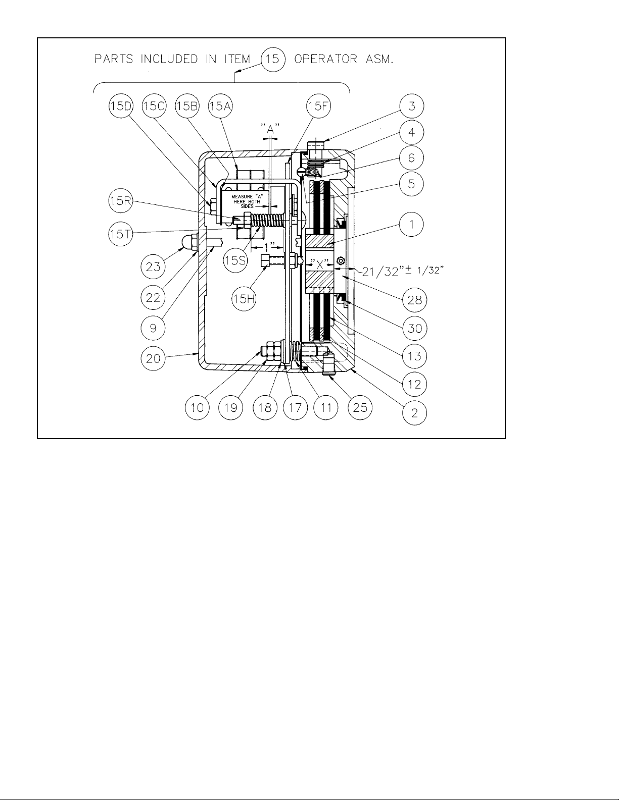
Figure 4
4
OPERATION
These brakes are spring set devices with an electrical
(magnet) release. They contain a rotating friction disc
which is driven by a hub mounted on the motor shaft. When
energized, the magnet compresses the torque springs,
removing the force pressing the stationary disc and friction
disc together. This permits free rotation of the shaft.
WARNING: Observe proper safety precautions in
applications where a brake failure would allow the load
to move in such a manner as to injure personnel. KEEP
PERSONNEL AWAY FROM LOAD AREAS.
If brake torque rating is higher than motor full-load torque
rating, use brake rating rather than motor rating when
selecting other drive components.
Take the following precautions when operating the brake:
1. Do not operate the brake at higher than normal static
torque capacity.
2. For applications with high inertia-type loads or rapid
cycling, the thermal capacity of the brake must be
considered.
3. High start-stop rates may damage motor. Consult
motor manufacturer if high cycling rates are
expected.
4. Be sure power supply conforms to electrical rating of
brake.
Manual Release
The brake is equipped with a manual release. Turn the
release knob (3) clockwise to stop position to release the
brake. The brake will remain released until the release knob
is turned counterclockwise (approx. 65
o
) or until the brake
coil is energized, automatically resetting the brake.
 Loading...