

Dings Dynamics Group 60 Series Coupler NEMA 2 User Manual
Number Inertia of Dimensions
Model Model of Thermal Rotating X
Standard Enclosed Rotating Torque Capacity Parts C AC
1-Piece 2-Piece
Housing Housing Discs Lb. Ft. HPS/MIN.* Lb.Ft.
2
Shaft Shaft
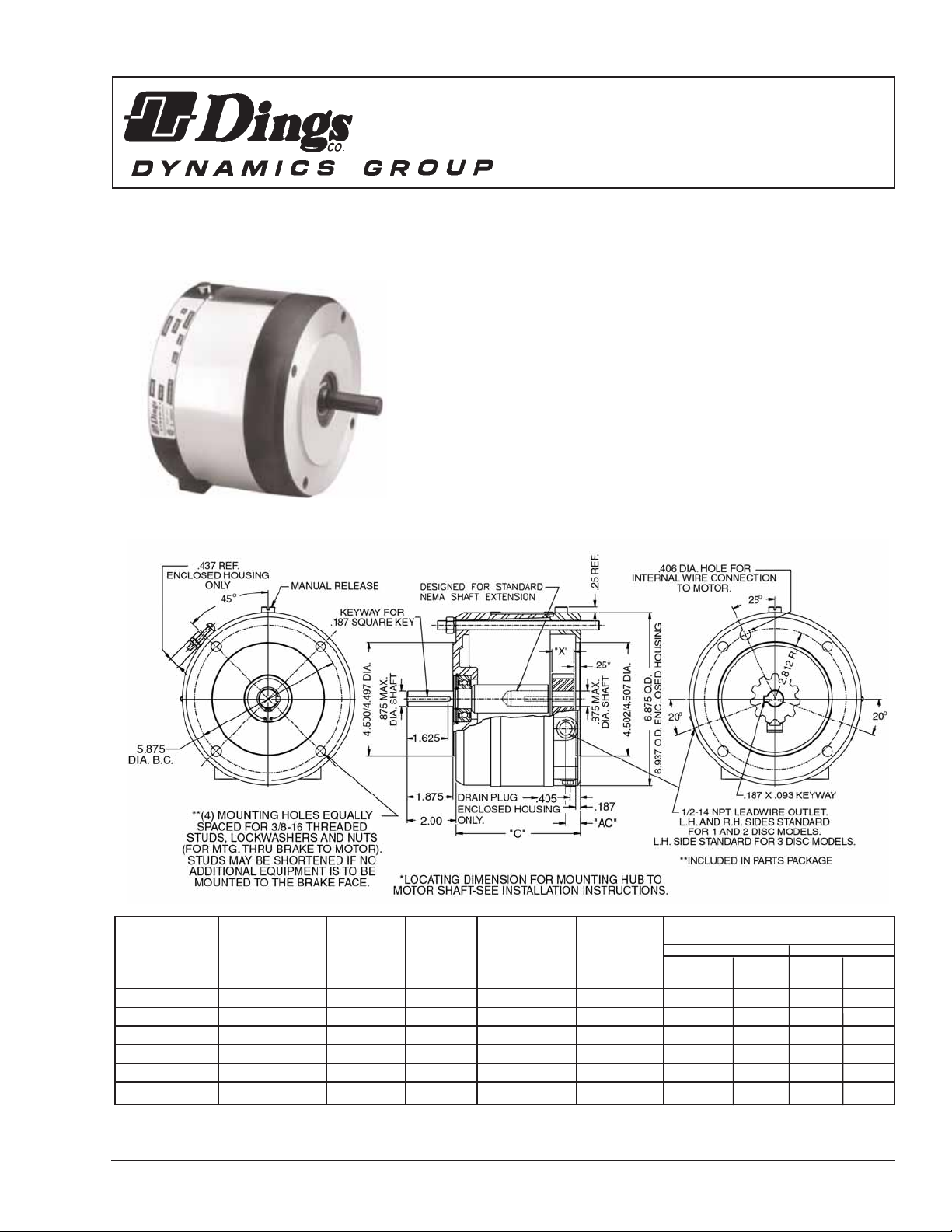
6-61001-551 4-61001-553 1 1.5 6 .006 4.94 .59 .81 .88
6-61003-551 4-61003-553 1 3 6 .006 4.94 .59 .81 .88
6-62006-551 4-62006-553 2 6 6 .010 4.94 .59 .81 .88
6-62010-551 4-62010-553 2 10 6 .010 4.94 .59 .81
-
6-63015-551 4-63015-553 3 15 6 .014 5.31 .87 1.19
-
6-63020-551 4-63020-553 3 20 6 .014 5.31 .87 1.19
-
60 Series Double C
Brake Instructions
Standard and
Enclosed Housing
G060849
Read carefully before attempting to assemble, install, operate or maintain the product described. Protect yourself
and others by observing all safety information. Failure to comply with instructions could result in personal injury
and/or property damage! Retain instructions for future reference. When unpacking the brake, inspect it carefully
for damage that may have occurred during transit.
Bulletin No. BK4650 (7/12/06)
4740 WEST ELECTRIC AVENUE MILWAUKEE, WI 53219 PHONE 414/672-7830 FAX 414/672-5354 www. dingsco.com
DESCRIPTION
This 60 Series magnetic disc brake is used on 56C,
143TC and 145TC face motors and speed reducers.
The brake is direct acting, electro-magnetically released,
and spring set. It uses rotating friction and stationary
disc contact to supply positive braking action. It retains
quick release and setting capabilities at all times.
Warning: Do not install or use these brakes in an
explosive atmosphere.
* Thermal capacity (HPS/MIN.) was determined under the following test conditions: a) Room temperature 72oF. b) Stopping time of one second or less.
c) Brake mounted in a horizontal position. d) Equal on and off times. e) 1800 RPM. f) Coil energized with 110% of rated voltage.
DIMENSIONS
Figure 1

WARNING:
Brake performance and features must be carefully
matched to the requirements of the application.
Consideration must be given to torque requirements,
especially where an overhauling condition exists, as well
as thermal capacity, ambient temperature, atmospheric
explosion hazards, type of enclosure and any other
unusual conditions.
Improper selection and installation of a brake and/or lack
of maintenance may cause brake failure which could
result in damage to property and/or injury to personnel.
If injury to personnel could be caused by brake failure,
additional means must be provided to insure safety of
personnel.
UNPACKING
When unpacking the brake, inspect it carefully for damage
that may have occurred during transit.
GENERAL SAFETY INFORMATION
NOTE: These brakes are not intended for accurate positioning
applications. They are designed for applications that require
rapid stopping and holding power, such as on conveyors, door
openers, etc.
1. For applications with high inertia-type loads or rapid
cycling, the thermal capacity of the brake must be
considered.
2. Observe all local electrical and safety codes, as well as
the National Electrical Code (NEC) and the Occupational
Safety and Health Act (OSHA).
3. Brake motors and brake gearmotors must be securely and
adequately grounded. This can be accomplished by
wiring with a grounded metal-clad raceway system, by
using a separate ground wire connected to the bare metal
of the motor frame, or other suitable means. Refer to
NEC Article 250 (Grounding) for additional information.
All wiring should be done by a qualified electrician.
4. Always disconnect power before working on or near a
brake motor, a brake gearmotor, or its connected load.
If the power disconnect point is out of sight, lock it in
the open position and tag it to prevent unexpected
application of power.
5. When working on the brake, be sure the load is
completely removed, secured or blocked to prevent
injury or property damage.
6. Provide guarding for all moving parts.
7. Be careful when touching the exterior of an operating
motor, gearmotor or brake. It may be hot enough to
cause injury or to be painful. This condition is normal
for modern motors, which operate at higher temperatures
when running at rated load and voltage.
8. Protect all electrical lead wires and power cables against
contact with sharp objects or moving parts.
9. Do not kink electrical lead wires and power cables, and
never allow them to touch oil, grease, hot surfaces or
chemicals.
INSTALLATION
CAUTION: To preserve pre-alignment of rotating discs
for ease of installation, do not operate manual release or
energize brake coil before installation.
NOTE: The brakes are designed for horizontal mounting.
Modification is required for vertical mounting. Brakes that
are modified will have a prefix on the model number of VO
(Vertical Over), VU (Vertical Under), or V (Vertical Over or
Under).
On enclosed models, the brake drain should be located at
the bottom. If the application causes excessive condensation
build-up, vertical mounting below the motor is not
recommended.
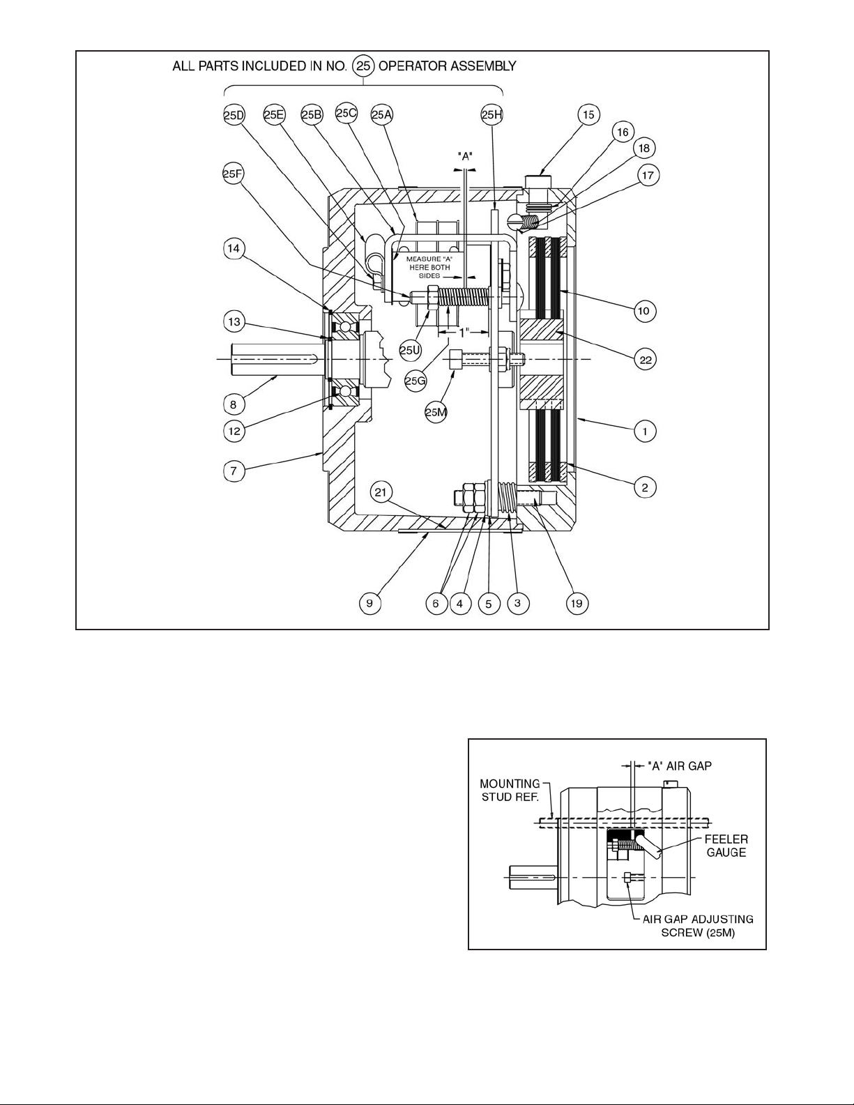
Number in parentheses refer to parts illustrated in Figs. 3, 4,
6, 7 and 10.
Placing Brake on Motor C Face
For models with two-piece shaft design:
1. Mount hub (22) over key on motor shaft 1/4” from the
motor mounting face as shown in Fig. 1. Part number
on hub to face away from motor. Use 3/16” square key
furnished. Key must extend to, and be flush with, end of
motor shaft. Tighten both setscrews in hub with 8 to 10
lb. ft. torque.
2. For enclosed housing models (4-60000-553), place
gasket (34) on motor C face.
3. Remove adapter housing (7). You may have to remove
wrap cover (9) and tap lightly with a soft mallet in the
openings in the side of the adapter housing. Place the
brake assembly onto the motor C face, engaging hub
splines into brake disc splines.
The release should be located at the top.
4. Screw in four 3/8-16 threaded rods (28) or (32) through
bracket (1) into motor C face (approx. 9/16” engagement
or 9 turns). Bring coil lead wires out of conduit hole
before installing the adapter housing. Align adapter
housing (7) with four threaded rods. NOTE: Arrow head
on adapter housing should be in line with manual release
knob (15); see Fig. 10.
Slide adapter housing onto threaded rods. turning output
shaft (8) so that the keyway in the brake shaft lines
up with the key in the motor shaft. Make sure adapter
housing seats against the bracket (1).
Tap adapter housing in place lightly. If excessive force
is required, the key may have to be filed.
5. If additional equipment is to be used, such as a gear
reducer, install a key into the brake shaft extension. For
enclosed housing models (4-60000-553), install gasket
(34) onto the brake C face.
Slide equipment onto threaded rods, aligning key in the
brake shaft with keyway in the additional equipment.
Fasten with lockwashers (29) and nuts (30).
6. If no additional equipment is used, fasten adapter
housing (7) with items (29) and (30). The threaded rods
may be cut off the suit the application.
2
For models with one-piece shaft design:
1. Place 3/16” square key furnished into motor keyway.
Key must extend to, and be flush with, end of motor
shaft. For enclosed housing models (4-60000-553), place
gasket (34) on motor C face.
2. Place brake assembly onto the motor shaft, aligning
the brake shaft keyway with key in the motor shaft. If
the key wants to ride up at the end of the motor shaft
keyway, push the key into the brake shaft with a
screwdriver.
Do not use excessive force to seat the brake against the
motor. If excessive force is required, the key may have to
be filed.
Brake bracket (1) must be flush with the motor mounting
face and adapter housing (7) must seat against the
bracket (1).
NOTE: Arrow head on adapter housing should be in line
with manual release knob (15); see Fig. 10. The release
should be located at the top.
3. Screw in four 3/8-16 threaded rods (28) or (32) through
housing (7) and bracket (1) into motor C face (approx.
9/16” engagement or 9 turns).
4. If additional equipment is to be used, such as a gear
reducer, install a key into the brake shaft extension. For
enclosed housing models (4-60000-553), install gasket
(34) onto the brake C face.
Slide equipment onto threaded rods, aligning key in the
brake shaft with keyway in the equipment. Fasten with
lockwashers (29) and nuts (30).
5. If no additional equipment is used, fasten brake assembly
with items (29) and (30). The threaded rods may be cut
off to suit the application.
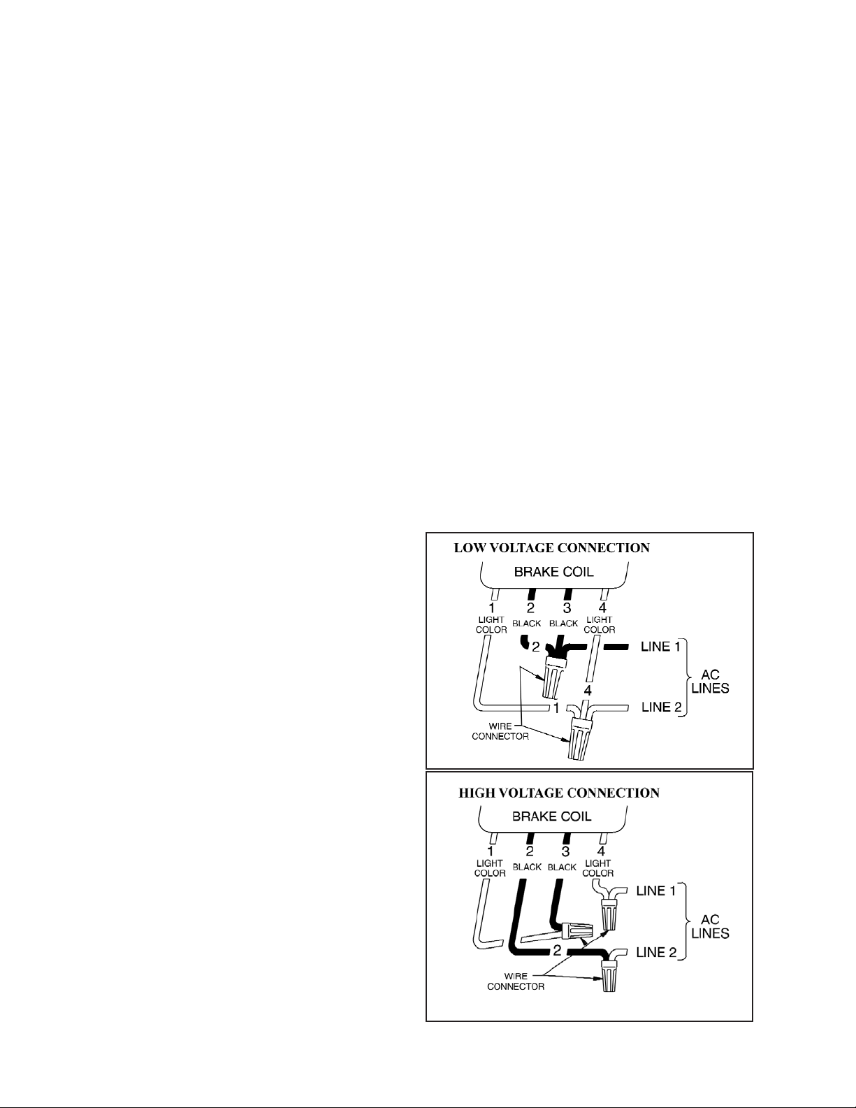
Connection of Coil Leads
After securing the brake to the motor, connect coil leads
for proper voltage per wiring diagram. (Fig. 2 shows dual
voltage coil). Incorrect connection can result in brake failure.
CAUTION: The voltage supplied to the coil must match
the voltage that the coils are connected for, or the coils
will burn out.
Single voltage coil:
Connect brake coil leads to any two line leads (single or three
phase) of same voltage and frequency as brake.
Dual voltage coil:
Connect leads 2 and 4 to any two motor line leads (single or
three phase) of same voltage as brake. Connect leads 1 and 3
as shown for voltage desired. Brake must be energized with
motor.
OPERATION
These brakes are spring set devices with an electrical
(magnet) release. They contain a rotating friction disc
that is driven by a hub mounted on the motor shaft. When
energized, the magnet compresses the torque springs,
removing the force pressing the stationary disc and friction
disc together. This permits free rotation of the shaft.
WARNING: Observe proper safety precautions in
applications where a brake failure would allow the load
to move in such a manner as to injure personnel.
KEEP PERSONNELAWAY FROM LOAD AREAS.
If brake torque rating is higher than motor full-load torque
rating, use brake rating rather than motor rating when
selecting other drive components.
Take the following precautions when operating the brake:
1. Do not operate the brake at higher than nominal static
torque capacity.
2. For applications with high inertia-type loads or rapid
cycling, the thermal capacity of the brake must be
considered.
3. High start-stop rates may damage motor. Consult motor
manufacturer if high cycling rates are expected.
4. Be sure power supply conforms to electrical rating of
brake.
Manual Release
The brake is equipped with a manual release. Turn the release
knob (15) clockwise to stop position to release the brake. The
brake will remain released until the release knob is turned
counterclockwise (approx. 65
o
) or until the brake coil is
energized, automatically resetting the brake.
Wiring Diagrams
3
Figure 2
4
MAINTENANCE
Caution: Before attempting to service or remove any
components, make certain that the power is disconnected
and that the load is completely removed, secured or
blocked to prevent injury or property damage.
Wear Adjustment
Caution: Load to be removed or blocked. Brake may be
inoperative during this procedure.
Before air gap “A” reaches .100”, adjustment is required. Any
delay in adjusting the magnet air gap will result in eventual
loss of torque.
Refer to Figs. 3 and 4.
1. To adjust, remove cover (9) to expose adjusting screws
(25M) and magnet air gap “A”.
2. Measure air gap “A” using 3/8” to 1/2” wide feeler gauge
as shown in Figs. 3 and 4.
3. Turn two square head adjusting screws (25M) until air
gap “A” measures:
.045/.050 for 1 disc models
.050/.055 for 2 disc models
.060/.065 for 3 disc models
Figure 3
Figure 4
 Loading...