

Dings Dynamics Group 50 Series48C frame User Manual
2-50 Series Standard
Brake Instructions
Bulletin No. BK4618 (3/12)
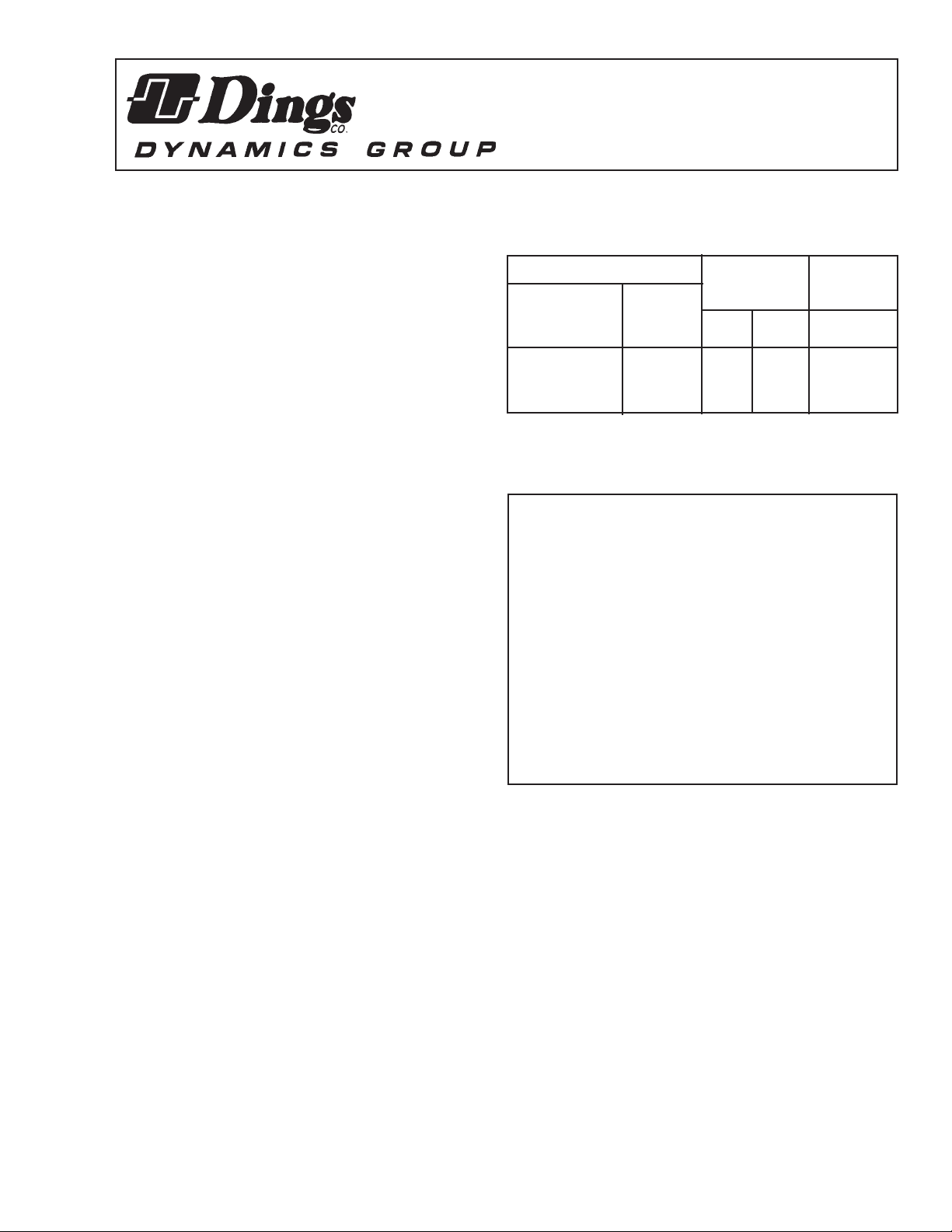
Standard Housing Inertia
Wt. Lbs. Rotating
Model Torque Parts
Lb. Ft. Net Pkg’d WK
2
in
Lb. Ft.
2
2-51001-050 1.5 6 7 .0023
2-51003-050 3 6 7 .0023
2-51006-050 6 6 7 .0023
Table 1. List of Models
WARNING
Brake performance and features must be carefully matched
to the requirements of the application.
Consideration must be given to torque requirements,
especially where an overhauling condition exists, as well
as thermal capacity, ambient temperature, atmospheric
explosion hazards, type of enclosure and any other unusual
conditions.
Improper selection and installation of a brake and/or lack of
maintenance may cause brake failure which could result in
damage to property and/or injury to personnel.
If injury to personnel could be caused by brake failure,
additional means must be provided to insure safety of
personnel.
Do not operate manual release or energize brake coil before
installation, in order to preserve prealignment of rotating
discs for ease of installation.
Figure 2. Dimensions of Brake
4740 W. Electric Avenue Milwaukee, WI 53219 414/672-7830 FAX 414/672-5354 www. dingsco.com
IMPORTANT
Read this bulletin carefully before installing or operating
this brake. Failure to comply with these instructions
cancels all warranties.
Figure 1. 50 Series Brake

DESCRIPTION
This brake is direct acting, electromagnetically released and spring
set. It uses rotating and stationary disc contact to supply positive
braking action. It retains quick release and setting capabilities at all
times.
Simplicity of design has reduced maintenance to an absolute
minimum. As with any electromechanical equipment, however, periodic inspection and adjustment will assure optimum performance. As
the friction disc wears, the magnet gap will increase. The magnet
gap should be checked periodically and adjusted when necessary.
INSTALLATION (See Figures 2, 3, 4 & 5)
Before installing, refer to section on Torque Selection.
1. Remove hub (2) from brake and position on motor shaft with key
per dimension shown in Figure 2. Stamped part number on hub
should face away from motor. Tighten hub set screws to shaft with
6-8 lb. ft. torque.
2. Remove the three cover screws (3) and cover (4) and position
brake over hub (2) on shaft. Bolt brake to motor flange with two 1/4”
flat head screws. (NOTE: Be sure anti-rattle spring (5) does not rest
in hub tooth space containing a set screw.)
3.Connect coil wire leads as indicated in Figure 3. Replace cover
and three cover screws.
MANUAL RELEASE (See Figure 4)
Manually release the brake by pushing the release lever (1) forward
until it has moved approximately 25
o
. THe brake will remain in the
released position as long as you hold the lever in this position.
MAINTENANCE AND SERVICE
FRICTION DISC REPLACEMENT (See Figure 4)
When total wear on rotating discs (11) reaches 1/16”, replace disc
as follows:
1. Remove the three cover screws (3), cover (4), nuts (9), magnet
assembly (8), washers (10), nuts (12), torque springs (13), armature
(14), nut (7), nut (6), pressure arm (15) and stationary disc (16).
2. Install new rotating disc (11) making sure anti-rattle spring (5) is
installed in position shown and does not rest in a hub tooth space
containing a set screw.
3. Reassemble all parts in reverse order.
NOTE: In reassembly, tighten nut (6) so that it just makes contact
with pressure arm (15). LOCATE nut (12) 1/2” from end of stud as
shown in Figure 4. Tighten nut (9) as described under MAGNET
ASSEMBLY REPLACEMENT. Readjust magnet air gap as described
under WEAR ADJUSTMENT.
WEAR ADJUSTMENT (See Figure 4).
As friction disc wears, magnet air gap “A” increases. When air gap
“A” reaches .150” maximum, adjust to .060”-.070”. To adjust: Hold
pivot nut (6), loosen lock nut (7), turn pivot nut (6) clockwise until air
gap “A” measures .080” at center of magnet. (NOTE: Air gap should
decrease slightly to measure .060”-.070”. When lock nut (7) is tightened against the pivot nut (6).) Hold pivot nut (6) and tighten lock
nut (7) against it. Operate brake several times to see if ;060”-.070”
air gap is maintained. If not, re-adjust following same procedure
again. Any delay in adjusting air gap will result in a loss of torque
and/or coil burn out.
MAGNET ASSEMBLY REPLACEMENT (See Figure 4)
Remove cover screws (3), cover (4), nuts (9) and magnet assembly
(8). Replace magnet assembly. Be sure rubber pads (10) are under
magnet bracket. TIghten nuts (9) to remove end play between nut
and magnet bracket. TIghten with an additional 1/3 turn (two flats on
nut). Check air gap as described under WEAR ADJUSTMENT and
replace cover and cover screws.
Figure 4. Brake Gap Adjustment
Figure 3. Wiring Diagram
 Loading...