

Dings 71010-46, 71015-46, 71015-38, 71010-38, 72025-38 Instructions Manual
...
Bulletin No. BK4620 (2/18)
70 Series
Double “C” Face
Brake Instructions
INSTALLATION
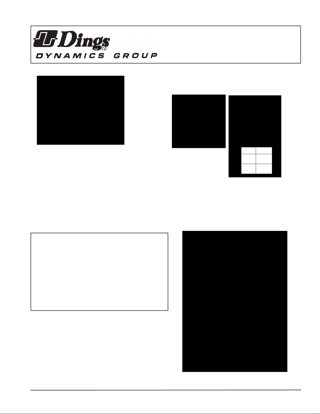
Refer to Figures 1 & 2
Insert key into motor shaft keyway. Key length to be as
shown below for models designated.
X
IMPORTANT
Read carefully before attempting to assemble, install,
operate or maintain the product described. Protect yourself
and others by observing all safety information. Failure to
comply with instructions could result in personal injury
and/or property damage! Retain instructions for future
reference. When unpacking the brake, inspect it carefully
for damage that may have occurred during transit.
WARNING
Brake performance and features must be carefully matched to the
requirements of the application.
Consideration must be given to torque requirements, especially where
an overhauling condition exists, as well as thermal capacity, ambient
temperature, atmospheric explosion hazards, type of enclosure and
any other unusual conditions.
Improper selection and installation of a brake and/or lack of maintenance may cause brake failure which could result in damage to property and/or injury to personnel.
If injury to personnel could be caused by brake failure, additional
means must be provided to insure safety of personnel.
Key must be full length
of keyway and flush with
end of shaft
Used on all models except
71010, 71015, 72025, and
72035 with 1-1/8” dia. shaft.
Slide brake onto motor shaft, aligning key in motor shaft
with keywayin brake shaft. Secure brake to motor “C” face
with four 1/2” socket head capscrews. Connect coil leads
per appropriate diagram.
Key to extend to
end of keyway
Model X ± 1/32
71010
1-15/16
71015
72025
2-7/16
72035
For models 71010, 71015,
72025 and 72035 with
1-1/8” dia. shaft.
DESCRIPTION
This brake is direct acting, electromagnetically released and spring set.
It uses rotating and stationary disc contact to supply positive braking
action. It retains quick release and setting capabilities at all times.
Simplicity of design has reduced maintenance to an absolute minimum.
As with any electromechanical equipment, however, periodic inspection
and adjustment will assure optimum performance. As the friction disc
wears, the magnet gap will increase. The magnet gap should be checked
periodically and adjusted when necessary. This brake is offered in 2
housing styles: Standard (NEMA 2) and Enclosed (NEMA 4).
Figure 1. Wiring Diagram
4740 WEST ELECTRIC AVENUEl MILWAUKEE, WI 53219l PHONE 414/672-7830 l FAX 414/672-5354 l www. dingsbrakes.com
MANUAL RELEASE
(See Figure 4)
To operate release, rotate two nuts (16) clockwise until stop
screw (14) hits pin. Brake will remain in released position until rods
are manually returned to original position, or until electrical power
is restored, automatically resetting the brake.
TORQUE ADJUSTMENT
(See Figures 2 & 4–Table 1)
Brake is factory set for rated torque per spring length “H”. To increase
stopping time and lower torque, turn two locknuts (9) counterclockwise,
increasing dimension “H”. Both springs must be set to the same length.
Do not decrease spring length “H” as this may cause coil to burn out.
MAINTENANCE AND SERVICE
WEAR ADJUSTMENT
(See Figures 2 & 4– Table 1)
Magnet gap “D” increases as friction discs wear. When gap approaches
“D” max., adjust gap to “D” min. dimension by turning nuts (23 and 24).
Magnet gap can vary from nominal + .005” between corners. After
setting gap, readjust torque spring length “H”.
CAUTION: MAGNET GAP MUST NOT EXCEED
“D” MAXIMUM.
FRICTION DISC REPLACEMENT
(See Figure 4 & Table 1)
When the rotating friction disc (4) wears down to a thickness of 7/32”,
replace disc. Remove brake from its associated equipment (reducermotor-etc.). Remove retaining ring (28) and press shaft (1) out of bearing in brake case (25). A wheel puller, utilizing openings in side of
case, can be used. Continue disassembling in this order: two nuts (26),
brake case (25), roll pins (17), manual release knobs (16), manual
release screws (14), manual release washers (12), manual release
shims(13), two nuts (24), magnet mounting plate assembly (18), two
nuts (23), two nuts (9), torque spring washers (8), torque springs (7),
pressure plate assembly (6) and discs (4) (5).
Lay bracket (2) on a flat table. Place shaft (1) in center of bracket, with
a spacer under hub. Spacer thickness to be 13/16”. Replace worn
friction discs (4) and reassemble disc pack. Continue reassembling in
reverse order, setting torque spring dimension “H,” and magnet gap “D”
min. (Table 1.). When assembling manual relase, turn release rod (10)
counter-clockwise until screw (14) strikes pin. Wind torsion spring (11)
about 1/4 turn and hook spring over pin.
NOTE: When assembling manual release mechanism, add only
enough shim washers (13) to obtain proper release action.
With too many shim washers, brake will not automatically reset when
electrical power is applied. With too few shim washers, motor shaft will
not turn freely with brake in manually released position.
IMPORTANT: Make sure release is working properly
before proceeding.
Place case (25) over shaft (1). Release brake by turning two nuts (16)
clockwise. Press bearing (in case) onto shaft by applying pressure to
bearing inner race. Complete assembly in this order: snap ring (28)
and two nuts (26).
NOTE:: Units with 1-3/8” dia. output shafts–remove brake case by
first removing outside retaining rin (41) and two nuts (26).
Then press shaft (1) out of bearing. Next remove remaining retaining
ring (41) and pull shaft out of brake.
Figure 2. Outline Drawing
MODEL
NUMBER
NEMA 2
MODEL
NUMBER
NEMA 4
# of
friction
discs
Torque
Lb-Ft
Weight
lbs.
Thermal
Capacity
HPS/Min
71010-38 71010-46 1 10 45 11 .069
71015-38 71015-46 1 15 45 11 .069 .070 .030 1.31
Inertia
WK
LB-FT
2
2
1.19 6.84
AC C
Max. Min.
.070 .030 1.31
DIMENSIONS
D
AH (Motor Shaft Length)
H
1-1/8” Dia. 1-3/8” Dia.
Max. Min. Max. Min.
*1.81 *1.69
72025-38 72025-46 2 25 49 12 .110 1.63 7.47 .070 .035 1.31 *2.44 *2.31
73025-38 73025-46 3 25 53 13 .150 2.25 8.09 .070 .040 1.25 3.13 2.94
72035-38 72035-46 2 35 49 12 .110 1.63 7.47 .070 .035 1.21 *2.44 *2.31
2.81 2.50
73035-38 73035-46 3 35 53 13 .150 2.25 8.09 .070 .040 1.27 3.13 2.94
73050-38 73050-46 3 50 53 13 .150 2.25 8.09 .070 .040 1.25 3.13 2.94
74075-38 74075-46 4 75 57 14 .190 2.88 8.72 .070 .040 1.21 3.25 3.00
Table1. List of Models and Dimensions
*Std. NEMA Motor Shafts will have to be shortened.
2
 Loading...