

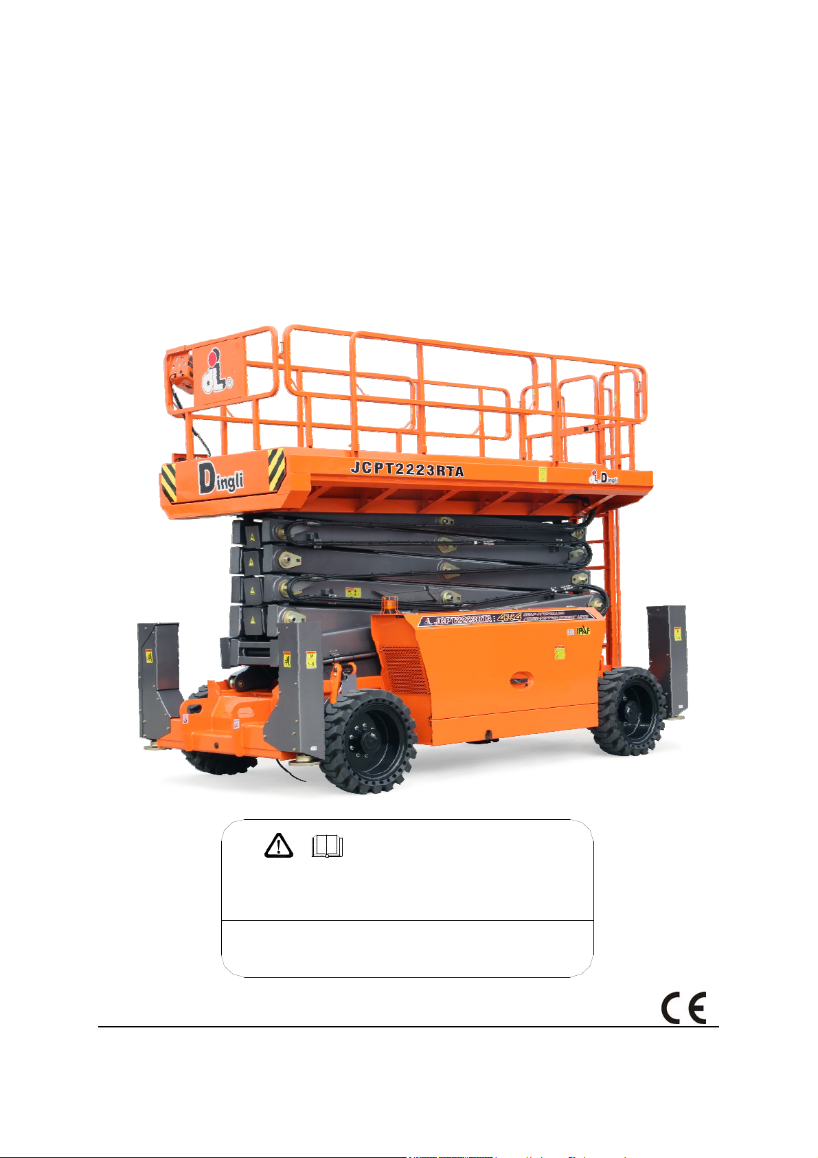
SELF-PROPELLED ROUGH-TERRAIN SCISSOR LIFTS
OPERATOR’S MANUAL
with Maintenance Information
( For JCPT2223RTA )
WARN ING
THE MANUFACTURER SHALL NOT BE HELD LIABLE IN CASE OF FAULTS
OR ACCIDENTS DUE TO NEGLIGENCE, INCAPACITY, INSTALLATION BY
UNQUALIFIED TECHNICIANS AND IMPROPER USE OF THE MACHINE
DO NO T O PER ATE THIS M AC HIN E U NTI L YOU READ AND UNDERSTAND
ALL THE DANGERS,WARNINGS AND CAUTIONS IN THIS MANUAL
Part Number: SM0117123
Zhejiang Dingli Machinery Co., Ltd. First Edition, September 2017

OPERATOR’S MANUAL with Maintenance Information
Version of the Record
1


OPERATOR’S MANUAL with Maintenance Information
Version of the Record
Version of the Record
Version Number Create Date
SM01117123_Rev1.0 ………………………………………………………………………… 2017-09
i


OPERATOR’S MANUAL with Maintenance Information
Important
Read, understand and obey these safety rules
and operating instructions before operating
this machine.
Only trained and authorized personnel shall be
permitted to operate this machine. This
manual should be considered a permanent
part of your machine and should remain with
the machine at all times. If you have any
questions, please call DINGLI Machinery.
Owners, Users and operators:
We appreciate your choice of our machine for
your application. Our number one priority is
user safety, which is best achieved by our joint
efforts. We feel that you make a major
contribution to safety if you, as the equipment
users and operators:
1 Comply with employer, job site and
governmental rules.
2 Read, understand and follow the
instructions in this and other manuals
supplied with this machine.
3 Use good safe work practices in a
commonsense way.
4 Only have trained / certified operators,
directed by informed and knowledgeable
supervision, running the machine.
Contents
Page
Safety Rules 1
Legend 8
Decals 9
Specifications 13
Control panel 14
Pre-operation Inspection 18
Workplace Inspection 20
Function Tests 21
Operating Instructions 27
Transport and Lifting Instructions 34
Maintenance 37
If there is anything in this manual that is not
clear or which you believe should be added,
please contact us.
Contact us:
Zhejiang Dingli Machinery Co., Ltd.
1255 Baiyun South Road. Leidian Town.
Deqing Zhejiang
China
Tel: +86-572-8681688
Schematic 64
Inspection and Repair Log 68
Fax: +86-572-8681690
Web: www.cndingli.com
E-mail:market@cndingli.com
i

OPERATOR’S MANUAL with Maintenance Information
Safety Rules
Danger
Failure to obey the instructions and
safety rules in this manual will
result in death or serious injury.
Do Not Operate Unless:
√ You learn and practice the principles of
safe machine operation contained in this
operator's manual.
1 Avoid hazardous situations.
Know and understand the safety rules
before going on to the next section.
2 Always perform a pre-operation
inspection.
3 Always perform function tests prior to
use.
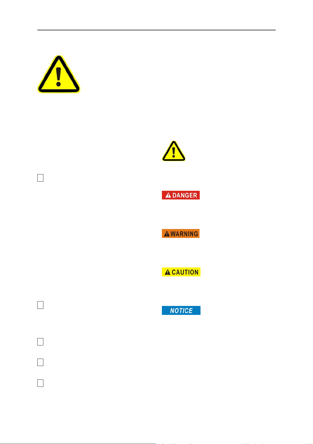
Decal Legend
DINGLI product decals use symbols, color
coding and signal words to identify the
following:
Safety alert symbol—used to alert
personnel to potential personal injury hazards.
Obey all safety messages that follow this
symbol to avoid possible injury or death.
Red—used to indicate the
presence of an imminently hazardous situation
which, if not avoided, will result in death or
serious injury.
Orange—used to indicate the
presence of a potentially hazardous situation
which, if not avoided, could result in death or
serious injury.
4 Inspect the workplace.
5 Only use the machine as it was
intended.
√ You read, understand and obey the
manufacturer's instructions and safety
rules— safety and operator's manuals and
machine decals.
√ You read, understand and obey employer's
safety rules and worksite regulations.
√ You read, understand and obey all
applicable governmental regulations.
√ You are properly trained to safely operate
the machine.
Yellow with safety alert
symbol—used to indicate the presence of a
potentially hazardous situation which, if not
avoided, may cause minor or moderate injury.
Blue without safety alert
symbol—used to indicate the presence of a
potentially hazardous situation which, if not
avoided, may result in property damage.
1
OPERATOR’S MANUAL with Maintenance Information
Safety Rules
The relevant conditions of using
the equipment
The surface of work ground should be flat and
hard with no obstacles in air and the safety
distance between the equipment and
high-tension line is adequate.
The environment temperature should be within
-20℃~40℃; Height above sea level ≤1000m.
The environment humidity ≤ 90%.
Electrical power: AC 110~230V±10%,
50~60Hz.
Work cycle
The life of designed work cycle is no more than
40000 times.
Intended Use
This machine is intended to be used only to lift
personnel, along with their tools and materials
to an aerial work site.
An operator on prescription or
over-the-counter drugs needs medical advice
on whether or not he/she can safely operate
machines.
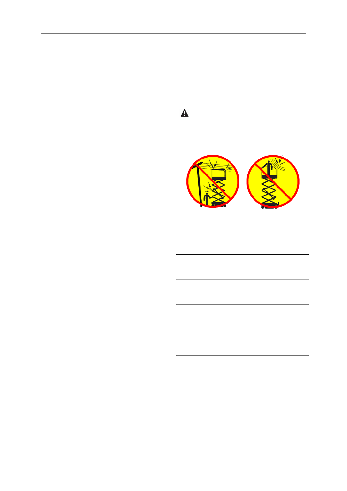
Electrocution Hazard
This machine is not electrically insulated and
will not provide protection from contact with or
proximity to electrical current.
Maintain safe distances from electrical power
lines and apparatus in accordance with
applicable governmental regulations and the
following chart.
Voltage
PhasetoPhase
Minimum Safe
Approach Distance
Meters
Safety Sign Maintenance
Replace any missing or damaged safety signs.
Keep operator safety in mind at all times. Use
mild soap and water to clean safety signs. Do
not use solvent-based cleaners because they
may damage the safety sign material.
Operator
Only the trained and qualified are permitted to
operate this machine. Always use safety belt
and helmet when aerially working.
If you are subject to dizziness or seizures, or
are bothered by heights, you must not operate
this type of machinery.
An operator must not use drugs or alcohol that
can change his/her alertness or coordination.
0 to 300V Avoid Contact
300V to 50kV 3.05
50kV to 200kV 4.60
200kV to 350kV 6.10
350kV to 500kV 7.62
500kV to 750kV 10.67
750kV to 1000kV 13.72
Allow for platform movement, electrical line
sway or sag and beware of strong or gusty
winds.
Keep away from the machine if it contacts
energized power lines. Personnel on the
ground or in the platform must not touch or
operate the machine until energized power
lines are shut off.
2
OPERATOR’S MANUAL with Maintenance Information
Safety Rules
Do not operate the machine during lightning or
storms.
Do not use the machine as a ground for
welding.
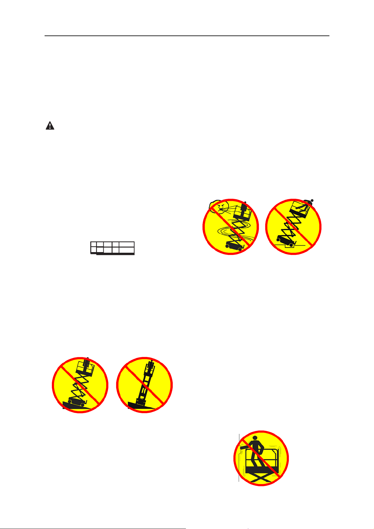
Tip-over Hazard
Occupants, equipment and materials must not
exceed the maximum platform capacity or the
maximum capacity of the platform extension.
Maximum capacity – JCPT2223RTA
Maximum occupants 4
Models with one extension deck
Platform allowable maximum load 750kg
Extension deck allowable maximum load 500kg
Only Only
firm, level surface. If the tilt alarm sounds
when the platform is raised, use extreme
caution to lower the platform.
For outdoor use machine, Do not raise the
platform when wind speeds may exceed 12.5
m/s. If wind speeds exceed 12.5 m/s when the
platform is raised, lower the platform and do
not continue to operate the machine.
Do not operate the machine in strong or gusty
winds. Do not increase the surface area of the
platform or the load. Increasing the area
exposed to the wind will decrease machine
stability.
Extension platform
deck
500kg 250kg
Work Area Safety
Do not raise the platform unless the machine
is on a firm, level surface.
Do not drive over 0.5km/h with the platform
raised.
Do not depend on the tilt alarm as a level
indicator. The tilt alarm sounds on the chassis
and in the platform when the machine is on a
slope.
Do not use the platform controls to free a
platform that is caught, snagged or otherwise
prevented from normal motion by an adjacent
structure. All personnel must be removed from
theplatformbeforeattemptingtofreethe
platform using the ground controls.
Use extreme care and slow speeds while
driving the machine in the stowed position
across uneven terrain, debris, unstable or
slippery surfaces and near holes and
drop-offs.
Do not drive the machine on or near uneven
terrain, unstable surfaces or other hazardous
conditions with the platform raised.
Do not push off or pull toward any object
outside of the platform.
If the tilt alarm sounds:
Lower the platform. Move the machine to a
3
OPERATOR’S MANUAL with Maintenance Information
Safety Rules
Maximum allowable manual force
Model Application
Outdoor 400N 4
JCPT2223RTA
Indoor 400N 4
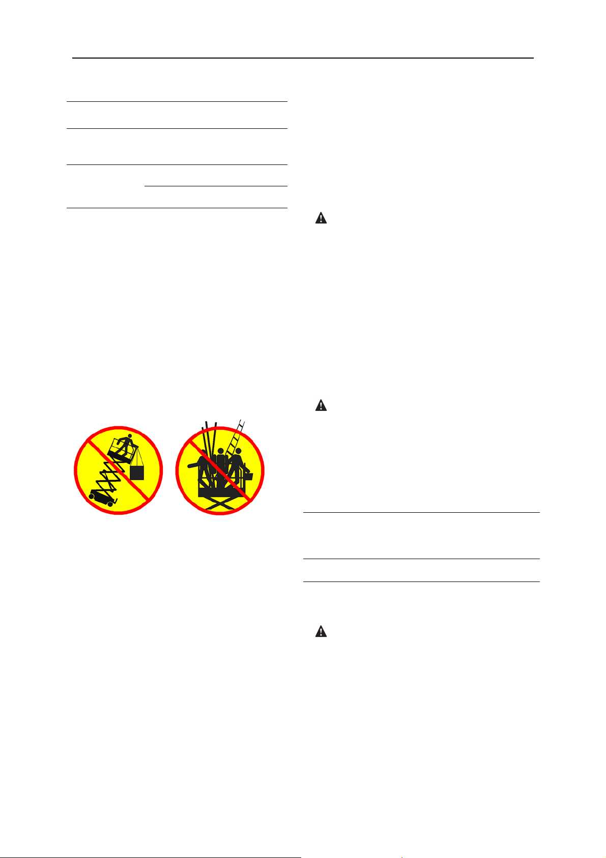
Do not use the machine as a crane.
Do not place or attach fixed or overhanging
loads to any part of this machine.
Do not push the machine or other objects with
the platform.
Do not contact adjacent structures with the
platform.
Do not alter or disable the limit switches.
Do not tie the platform to adjacent structures.
Do not place loads outside the platform
perimeter.
manual
force
Maximum
occupants
handled by person(s) in the platform.
Do not use the machine on a moving or mobile
surface or vehicle.
Be sure all tires are in good condition, air-filled
tires are properly inflated and lug nuts are
properly tightened.
Crushing Hazard
Keep hands and limbs out of scissors.
Keep hands clear when folding rails.
Use common sense and planning when
operating the machine with the controller from
the ground. Maintain safe distances between
the operator, the machine and fixed objects.
Maintain a firm grasp on the platform rail when
removing the rail pins. Do not allow the
platform guard rails to fall.
Operation on Slopes Hazard
Do not alter or disable machine components
that in any way affect safety and stability.
Do not replace items critical to machine
stability with items of different weight or
specification.
Do not modify or alter an aerial work platform
without prior written permission from the
manufacturer. Mounting attachments for
holding tools or other materials onto the
platform, toe boards or guard rail system can
increase the weight in the platform and the
surface area of the platform or the load.
Do not place ladders or scaffolds in the
platform or against any part of this machine.
Do not drive the machine on a slope that
exceeds the slope and side slope rating of the
machine.
Slope rating applies to machines only in the
stowed position.
Maximum
Model
JCPT2223RTA 30% (17°) 25% (14°)
Note: Slope rating is subject to ground
conditions and adequate traction.
slope rating
stowed position
Maximum
side slope rating
stowed position
Fall Hazard
The guard rail system provides fall protection.
During operation, occupants in the platform
must wear a full body harness with a lanyard
attached to an authorized lanyard anchorage
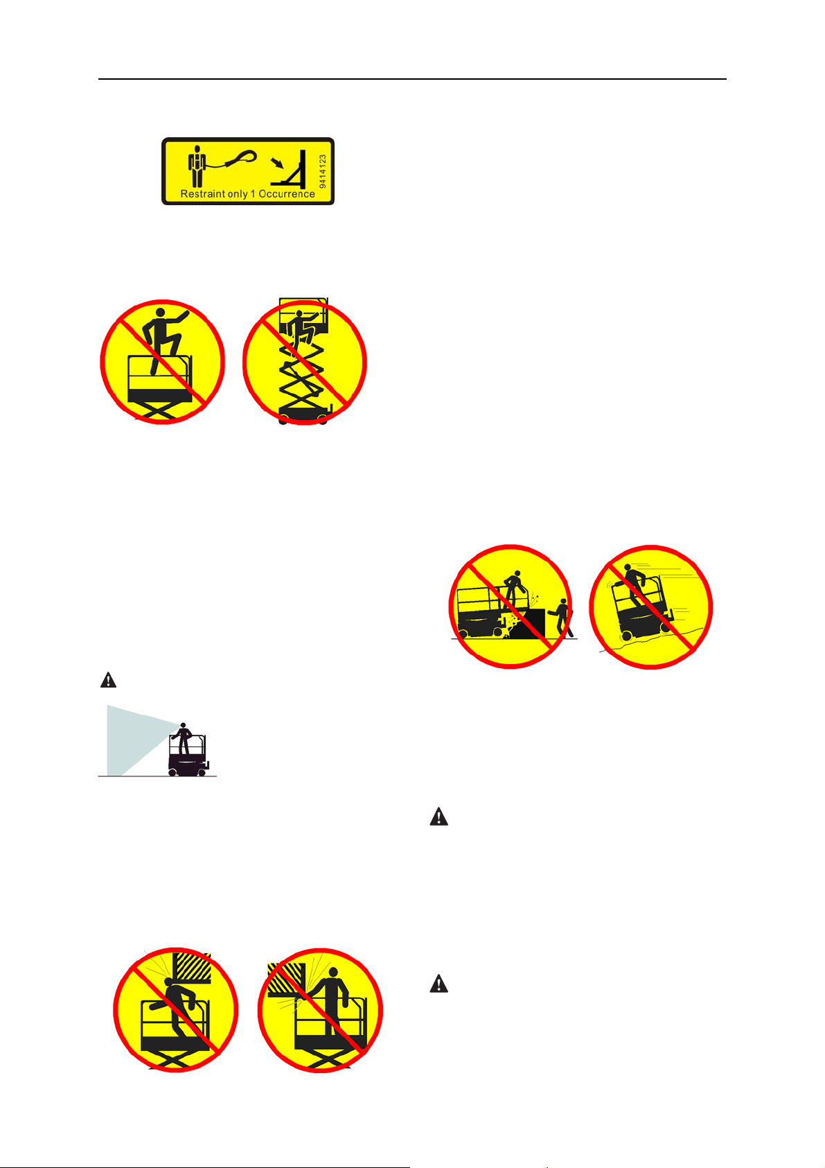
point. Attach only one (1) lanyard per lanyard
anchorage point.
Do not transport tools and materials unless
they are evenly distributed and can be safely
4
OPERATOR’S MANUAL with Maintenance Information
Do not sit, stand or climb on the platform guard
rails. Maintain a firm footing on the platform
floor at all times.
Safety Rules
Be aware of crushing hazards when grasping
the platform guard rail.
Operators must comply with employer, job site
and governmental rules regarding use of
personal protective equipment.
Observe and use color-coded direction arrows
on the platform controls and platform decal
plate for drive and steer functions.
Do not operate a machine in the path of any
crane or moving overhead machinery unless
the controls of the crane have been locked out
and/or precautions have been taken to prevent
any potential collision.
Do not climb down from the platform when
raised.
Keep the platform floor clear of debris.
Close the entry gate before operating.
Do not operate the machine unless the guard
rails are properly installed and the entry is
secured for operation.
Do not enter or exit the platform unless the
machine is in the stowed position.
Collision Hazard
Be aware of limited sight distance and blind
spots when driving or operating.
Be aware of extended platform position(s)
when moving the machine.
No stunt driving or horseplay while operating a
machine.
Do not lower the platform unless the area
below is clear of personnel and obstructions.
Limit travel speed according to the condition of
the ground surface, congestion, slope, location
of personnel, and any other factors which may
cause collision.
Component Damage Hazard
Do not use any battery or charger greater than
12V to jump-start the engine.
Check the work area for overhead obstructions
or other possible hazards.
Do not use the machine as a ground for
welding.
Explosion and Fire Hazard
Do not start the engine if you smell or detect
liquid petroleum gas (LPG), gasoline, diesel
fuel or other explosive substances.
5

OPERATOR’S MANUAL with Maintenance Information
Safety Rules
Do not refuel the machine with the engine
running.
Refuel the machine and charge the battery
only in an open, well-ventilated area away
from sparks, flames and lighted tobacco.
Do not operate the machine in hazardous
locations or locations where potentially
flammable or explosive gases or particles may
be present.
Do not spray ether into engines equipped with
glow plugs.
Damaged Machine Hazard
Do not use a damaged or malfunctioning
machine.
Conduct a thorough pre-operation inspection
of the machine and test all functions before
each work shift. Immediately tag and remove
from service a damaged or malfunctioning
machine.
Be sure all maintenance has been performed
as specified in this manual. Be sure all decals
are in place and legible.
Be sure the operator’s manual is complete,
legible and in the storage container located in
the platform.
advised when performing a pre-operation
inspection. All compartments must remain
closed and secured during operation.
Outrigger Safety
Do not lower the outriggers unless the
machine is on a firm surface. Avoid drop-offs,
holes, unstable or slippery surfaces and other
possible hazardous conditions.
When the auto level function is not being used
and the outriggers are being lowered
individually, the steer-end outriggers must be
lowered first.
Do not raise the platform unless the machine
is level. Do not set the machine up on a
surface where it cannot be leveled using only
the outriggers.
Do not raise the platform unless all four
outriggers are properly lowered, the footpads
are in firm contact with the ground and the
machine is level.
Do not adjust the outriggers while the platform
is raised.
Do not drive while the outriggers are lowered.
Battery Safety
Bodily Injury Hazard
Always operate the machine in a
well-ventilated area to avoid carbon monoxide
poisoning.
Do not operate the machine with a hydraulic oil
or air leak. An air leak or hydraulic leak can
penetrate and/or burn skin.
Improper contact with components under any
cover will cause serious injury. Only trained
maintenance personnel should access
compartments. Access by the operator is only
Burn Hazard
Batteries contain acid. Always wear protective
clothing and eye wear when working with
batteries.
Avoid spilling or contacting battery acid.
Neutralize battery acid spills with baking soda
and water.
6

OPERATOR’S MANUAL with Maintenance Information
Explosion Hazard
Keep sparks, flames and lighted tobacco away
from batteries. Batteries emit explosive gas.
Electrocution/ Hazard
Avoid contact with electrical terminals.
pollute Hazard
Safety Rules
Dispose of old battery must comply with job
site and governmental rules.
Lockout after Each Use
1 Select a safe parking location - firm level
surface, clear of obstructions and traffic.
2 Lower the platform.
3 Turn the key switch to the off position and
remove the key to secure from
unauthorized use.
4 Chock the wheels.
7
OPERATOR’S MANUAL with Maintenance Information
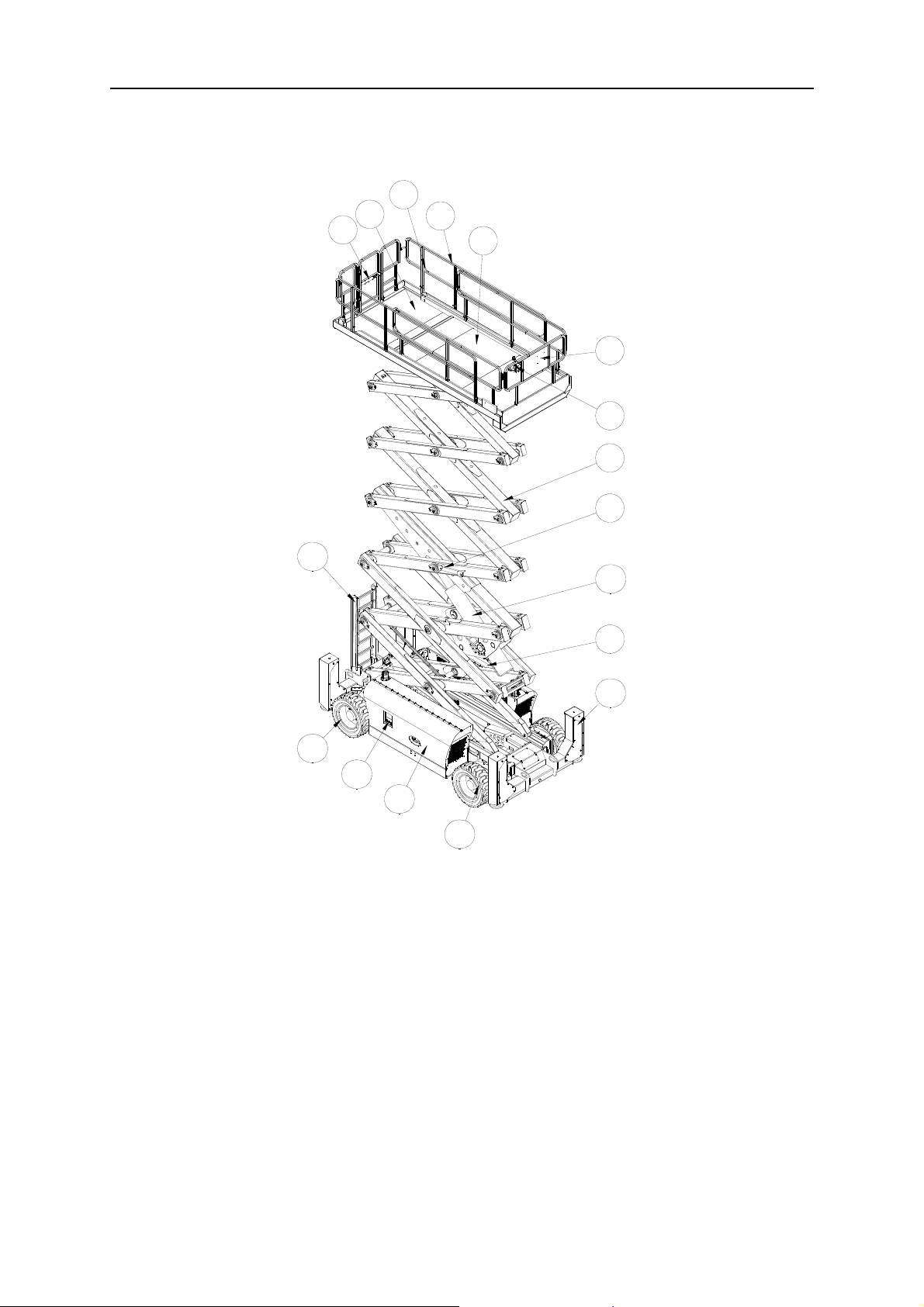
Legend
Legend
3
2
1
4
5
6
7
8
9
17
10
11
12
16
15
14
13
1 Platform entry gate 10 Lift Cylinder
2 Main Platform 11 Engine(behind cover)
3 Lanyard anchorage point 12 Outrigger
4 Platform guard rails 13 Front wheel
5 Platform extensions
14 Hydraulic tanks、Fuel tanks (behind cover)
6 Manual storage containers 15 Ground controls
7 Platform controls 16 Rear wheel
8 Scissor Arms 17.Entry ladder
9. Safety arm
8

OPERATOR’S MANUAL with Maintenance Information
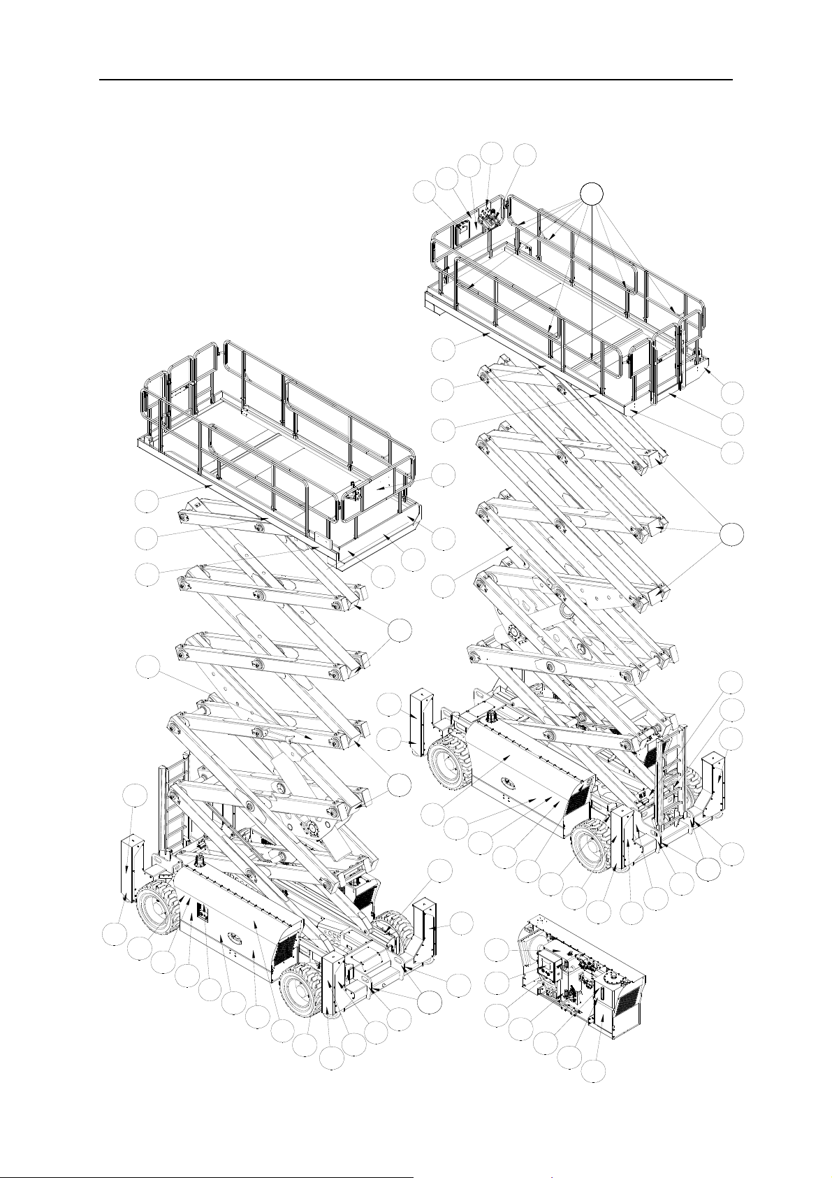
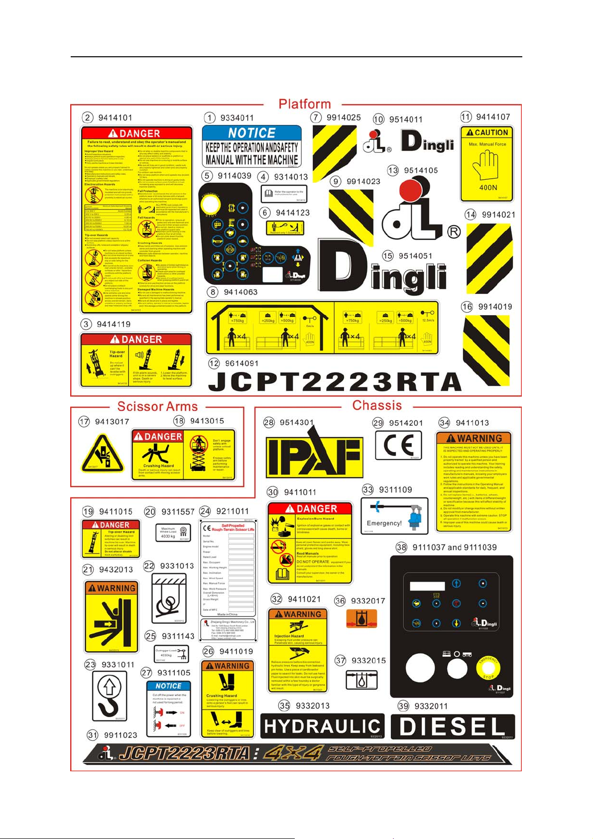
Decals
Decal Inspection
Use the pictures on the next page to verify that all decals are legible and in place.
Below is a numerical list with quantities and descriptions.
No. Part No. Description Qty. Remark
1 9334011 Notice – Operator’s Manual Storage 1
2 9414101 Danger – Safety Rules 1
3 9414119 Danger – Tip-over Hazard 1
4 9314013
5 9114013 Label – Platform Console Panel 1
6 9414123 Label – Lanyard Anchorage 6
7 9914025 Cosmetic – Warning 1
8 9414063 Label – Capacity 750kg 1
9 9914023 Cosmetic – Warning 1
10 9514011 Cosmetic – Mark 2
11 9414107 Caution – Max. Manual Force: 400N 2
12 9614091 Cosmetic – JCPT2223RTA 2
13 9514105 Cosmetic – Mark 1
14 9914021 Cosmetic – Warning 1
15 9514051 Cosmetic – Mark 1
Instructions – Refer the operator to the instructions
for use
2
16 9914019 Cosmetic – Warning 1
17 9413017 Warning – Crushing Hazard 7
18 9413015 Danger – Safety Arm 2
19 9411015 Danger – Tip-over hazard 1
20 9311557 Instructions – Maximum wheel load: 4030kg 4
21 9432013 Warning – Crushing Hazard 4
22 9331013 Instructions – Tie Down Point 4
9

OPERATOR’S MANUAL with Maintenance Information
Decals
No. Part No. Description Qty. Remark
23 9331011 Instructions – Lift Point 4
24 9211011 Decal – Manufacturer’s Plate 1
25 9311143 Instructions – Outrigger load: 4030kg 4
26 9411019 Warning – Crushing Hazard 4
27 9311105 Notice – Main power switch operation 1
28 9514301 Cosmetic – IPAF 2
29 9514201 Cosmetic – CE 2
30 9411011 Danger – Explosion/Burn Hazard 1
Instructions – JCPT2223RTA 4×4
31 9911023
SELF-PROPELLED ROUGH
TERRAIN SCISSOR LIFTS
2
32 9411021 Warning – Injection Hazard 1
33 9311109 Instructions – Emergency 1
34 9411013 Warning – Inspected and operating properly 1
35 9332013 Instructions – Hydraulic Oil 1
36 9332017 Instructions – Lowest Hydraulic Oil Level 2
37 9332015 Instructions – Highest Hydraulic Oil Level 2
9111011 Label – Ground Console Panel 1
38
9111013 Label – Ground Console Panel 1
39 9332011 Instructions – Diesel 1
On the Hydraulic
Oil Tank
On the Hydraulic
Oil Tank and
Diesel Tank
On the Diesel
Tank
10
OPERATOR’S MANUAL with Maintenance Information
Decals
4
3
2
1
12
5
66666666
25
26
29
12
11
10
18
28
34
11
10
13
14
15
16
1717
26
25
1717
31
30
29
39
38
37
28
36
27
37
20
36
26
35
25
22
24
21
20
21
4
33
32
31
20
26
25
22
21
23
23
22
23
23
7
8
9
17181717
19
20
21
22
11
OPERATOR’S MANUAL with Maintenance Information
Decals
12

Model JCPT2223RTA
OPERATOR’S MANUAL with Maintenance Information
Specifications
Height, working maximum 22m
Height, platform maximum 20m
Height, drive maximum 12 m
Height, stowed maximum
Rails up
Height, stowed maximum
Rails folded
Width 2.35m
Length, platform retracted
Platform dimensions
Platform length x width
Platform extension length 2.0m
Maximum load capacity 750kg
Maximum wind speed 12.5m/s
4.35m×1.85m
3.68m
2.9m
4.9m
Airborne noise emissions <80 dB
Maximum sound level at normal operating
workstations (A-weighted)
Vibration value does not exceed 2.5m / s
Maximum slope rating ,
Stowed position
Maximum side slope rating
Stowed position
Note: Slope rating is subject to ground
conditions and adequate traction.
Maximum working slope
Drive speeds
Stowed, maximum 6.6 km/h
Platform raised, maximum 0.5 km/h
Floor loading information
2
30%
25%
X-2°, Y-3°
Wheelbase 3.13m
Turning radius (outside) 4.6m
Turning radius (inside) 2.1m
Ground clearance 30cm
Weight See Serial Label
Machine weights vary with option configurations
Controls Proportional
AC outlet in platform Standard
Maximum hydraulic pressure
(functions)
Tire size 355/55D625
240bar
Tire load, maximum 4030kg
Outrigger load, maximum 4030kg
Tire contact pressure
Occupied floor pressure
Note: Floor loading information is approximate
and does not incorporate different option
configurations. It should be used only with
adequate safety factors.
Continuous improvement of our products is a
DINGLI policy. Product specifications are
subject to change without notice or obligation.
740kPa
11. 8kP a
13
OPERATOR’S MANUAL with Maintenance Information
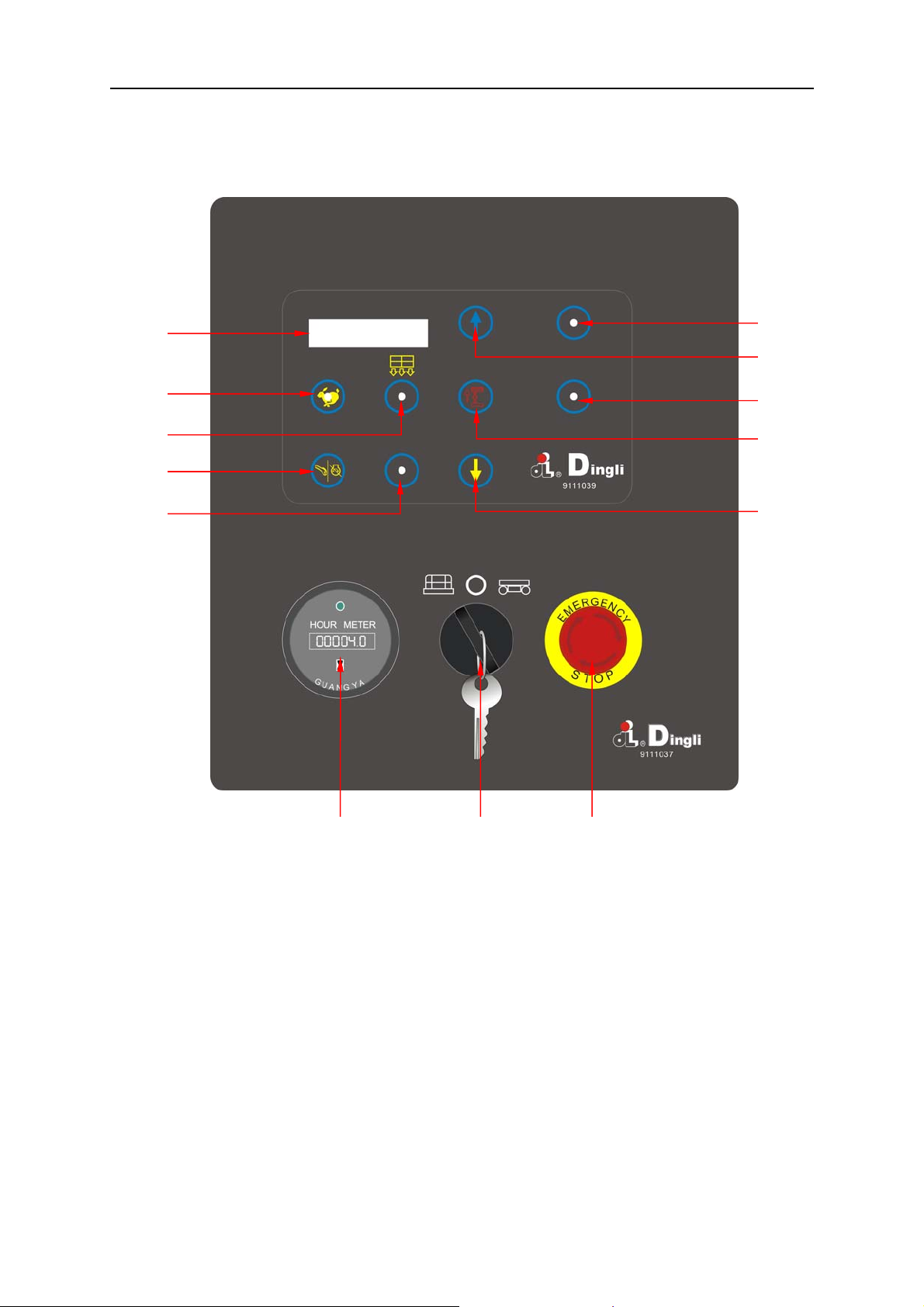
Control Panel
Ground Control Panel
1
13
12
2
3
11
10
4
5
9
678
1 LED readout screen 8 Red Emergency Stop button
2 Idle select button 9 Platform down button
3 Overload indicator light
4 Engine start/flameout button
5 Engine RPM display button
6 Hour meter
7 Key switch for platform / off / ground control
selection
14
10 Lift function enable button
11 Standby
12 Platform up button
13 Standby

Ground Control Panel
1LED
Diagnostic readout
2 Idle select button
Press this button to select the engine idle
setting. Light on indicates high idle is
selected. Light off indicates low idle is
selected.
3 Overload indicator light
OPERATOR’S MANUAL with Maintenance Information
Control Panel
8 Red Emergency Stop button
Push in the red Emergency Stop button to
the off position to stop all functions. Turn
the red Emergency Stop button clockwise
to the on position to operate the machine.
9 Platform down button
Press this button and the platform will
lower
Light on indicates when overloaded.
4 Engine start/flameout button
Press this button to start/flameout the
engine.
5 Engine RPM display button
Press this button to show the engine
RPM.
6 Hour meter
The hour meter displays the number of
hours the machine has operated.
7 Key switch for platform / off / ground Turn
the key switch to the platform position and
the platform controls will operate.
Turn the key switch to the off position and
the machine will be off. Turn the key
switch to the base position and the ground
controls will operate.
10 Lift function enable button
Press this button to activate the lift
function.
11 Standby
12 Platform up button
13 Standby
15

OPERATOR’S MANUAL with Maintenance Information
Control Panel
Platform Control Panel
1
16
2
15
3
4
5
14
13
12
6
7
8
11
7
77 9 10
1 Red Emergency Stop button 9 Steer mode select button
2 Drive function select button 10 LED
3 Platform retractable enable button
4 Engine high speed idle select button 12 Engine lower speed Idle select button
5 Horn button 13 Lift function select button
6 Differential lock enable button 14 Proportional control handle
7 Outrigger control button 15 Thumb rocker switch for steer function
8 Outrigger auto level button 16 Function enable button
11 Engine start / flameout button
16

OPERATOR’S MANUAL with Maintenance Information
Control Panel
Platform Control Panel
1 Red Emergency Stop button
Push in the red Emergency Stop button to
the off position to stop all functions. Pull out
the red Emergency Stop button to the on
position to operate the machine.
2 Drive function select button
Press this button to activate the drive
function.
3 Platform retractable enable button
Press and hold this button to activate the
platform retractable function.
4 Engine high speed idle select button
Press this button to select the engine idle
setting. Light on indicates high idle is
selected.
5 Horn button
Press this button and the horn will sound.
Release the button and the horn will stop.
6 Differential lock enable button
Press and hold this button to activate the
differential lock function.
7 Outrigger control button
Press this button to activate the individual
outrigger up/down function.
8 Outrigger auto level button
Press this button to activate the auto level
function.
9 Steer mode select button
Press this button to select steer mode :FS
mode (Front Steer mode), AS mode (All
wheel Steer mode), CS mode (Crab Steer
mode).
10 LED
Diagnostic readout and steer mode and
battery charge indicator.
11 Engine start / flameout button
Press this button to start/ flameout the
engine.
12 Engine lower speed Idle select button
Press this button to select the engine
idle setting. Light on indicates high idle
is selected.
13 Lift function select button
Press this button to activate the lift
function.
14 Proportional control handle
Move the control handle control the
drive function, Lift function, and platform
retractable function outrigger retractable
function
15 Thumb rocker switch for steer function
Press the thumb rocker switch in either
direction to activate steer function.
16 Function enable switch
Lift function: Press and hold the function
enable switch to enable the lift function
on the platform control handle. Move the
control handle in the direction indicated
by the blue arrow and the platform will
raise. Move the control handle in the
direction indicated by the yellow arrow
and the platform will lower. The descent
alarm should sound while the platform is
lowering.
Drive function: Press and hold the
function enable switch to enable the
drive function on the platform control
handle. Move the control handle in the
direction indicated by the blue arrow on
the control panel and the machine will
moveinthedirectionthatthebluearrow
points. Move the control handle in the
direction indicated by the yellow arrow
on the control panel and the machine
will move in the direction that the yellow
arrow points.
17

OPERATOR’S MANUAL with Maintenance Information
Pre-operation Inspection
Do Not Operate Unless:
√ You learn and practice the principles of
safe machine operation contained in this
operator's manual.
1 Avoid hazardous situations.
2 Always perform a pre-operation
inspection.
Know and understand the pre-operation
inspection before going on to the next
section.
3 Inspect the workplace.
4 Always perform function tests prior to
use.
5 Only use the machine as it was
intended.
Fundamentals
It is the responsibility of the operator to
perform a pre-operation inspection and routine
maintenance.
The pre-operation inspection is a visual
inspection performed by the operator prior to
each work shift. The inspection is designed to
discover if anything is apparently wrong with a
machine before the operator performs the
function tests.
The pre-operation inspection also serves to
determine if routine maintenance procedures
are required. Only routine maintenance items
specified in this manual may be performed by
the operator.
Refer to the list on the next page and check
each of the items.
If damage or any unauthorized variation from
factory delivered condition is discovered, the
machine must be tagged and removed from
service.
Repairs to the machine may only be made by
a qualified service technician, according to the
manufacturer's specifications. After repairs are
completed, the operator must perform a
pre-operation inspection again before going on
to the function tests.
Scheduled maintenance inspections shall be
performed by qualified service technicians,
according to the manufacturer's specifications
and the requirements listed in this manual.
18

Pre-operation Inspection
OPERATOR’S MANUAL with Maintenance Information
Pre-operation Inspection
Be sure that the operator’s manual are
complete, legible and in the storage
container located in the platform.
Be sure that all decals are legible and in
place. See Decals section.
Check for engine oil leaks and proper oil
level. Add oil if needed. See Maintenance
section.
Check for hydraulic oil leaks and proper oil
level. Add oil if needed. See Maintenance
section.
Check for engine coolant leaks and proper
level of coolant. Add coolant if needed.
See Maintenance section.
Check for battery fluid leaks and proper
fluid level. Add distilled water if needed.
See Maintenance section.
Check the following components or areas for
damage, improperly installed or missing parts
and unauthorized modifications:
□ Electrical components, wiring and
electrical cables
□ Safety arm
□ Platform extension(s)
□ Scissor pins and retaining fasteners
□ Platform control joystick
□ Oscillate Axle
□ Differential lock
□ Outrigger housings and footpads
Check entire machine for:
□ Cracks in welds or structural
components
□ Dents or damage to machine
□ Be sure that all structural and other
critical components are present and
all associated fasteners and pins are
in place and properly tightened
Note: If the platform must be raised to inspect
the machine, make sure the safety arm is in
place. See Operating Instructions section.
□ Hydraulic hoses, fittings, cylinders and
manifolds
□ Fuel and hydraulic tanks
□ Drive motors
□ Wear pads
□ Tires and wheels
□ Engine and related components
□ Limit switches, alarms and horn
□ Nuts, bolts and other fasteners
□ Platform overload components
□ Platform entry gate
□ Beacon and alarms (if equipped)
19

OPERATOR’S MANUAL with Maintenance Information
Workplace Inspection
Do Not Operate Unless:
√ You learn and practice the principles of
safe machine operation contained in this
operator's manual.
1 Avoid hazardous situations.
2 Always perform a pre-operation
inspection.
3 Inspect the workplace.
Know and understand the workplace
inspection before going on to the next
section.
4 Always perform function tests prior to
use.
5 Only use the machine as it was
intended.
Fundamentals
The workplace inspection helps the operator
determine if the workplace is suitable for safe
machine operation. It should be performed by
the operator prior to moving the machine to the
workplace.
It is the operator's responsibility to read and
remember the workplace hazards, then watch
for and avoid them while moving, setting up
and operating the machine.
Workplace Inspection
Be aware of and avoid the following hazardous
situations:
- Drop-offs or holes
- Bumps, floor obstructions or debris
- Sloped surfaces
- Unstable or slippery surfaces
- Overhead obstructions and high voltage
conductors
- Hazardous locations
- Inadequate surface support to withstand all
load forces imposed by the machine
- Wind and weather conditions
- The presence of unauthorized personnel
- Other possible unsafe conditions
20

OPERATOR’S MANUAL with Maintenance Information
r
Function Tests
Do Not Operate Unless:
√ You learn and practice the principles of
safe machine operation contained in this
operator's manual.
1 Avoid hazardous situations.
2 Always perform a pre-operation
inspection.
3 Inspect the workplace.
4 Always perform function tests prio
to use.
Know and understand the function tests
before going on to the next section.
5 Only use the machine as it was
intended.
Fundamentals
The function tests are designed to discover
any malfunctions before the machine is put
into service.
The operator must follow the step-by-step
instructions to test all machine functions.
A malfunctioning machine must never be used.
If malfunctions are discovered, the machine
must be tagged and removed from service.
Repairs to the machine may only be made by
a qualified service technician, according to the
manufacturer's specifications.
After repairs are completed, the operator must
perform a pre-operation inspection and
function tests again before putting the machine
into service.
21

OPERATOR’S MANUAL with Maintenance Information
Function Tests
1 Select a test area that is firm, level and
free of obstruction.
At the Ground Controls
2 Pull out the platform red Emergency Stop
button to the on position.
3 Turn the red Emergency Stop button
clockwise to the on position.
4 Turn the key switch to ground control.
5 0bserve the diagnostic LED readout on the
ground controls.
⊙ Result: The LED readout will come on and
display SYSTEM READY.
6 Start the engine. See Operating
Instructions section.
Test Emergency Stop
7 Push in the ground red Emergency Stop
button to the off position.
⊙ Result: The engine should turn off and no
functions should operate.
8 Turn the red Emergency Stop button
clockwise to the on position and restart the
engine.
Test Up/Down Functions and
Function Enable
A buzzer with different sound frequency is
controlled in central system. The descent
alarm sounds at 60 beeps per minute. The
alarm that goes off when the machine is not
level sounds at 150 beeps per minute. An
optional automotive-style horn is also
available.
9 Do not press the lift function enable button.
Press and hold the platform up/down
button.
⊙ Result: No function should operate.
10 Press and hold the lift function enable
button. Press and hold the platform up
button.
⊙ Result: The platform should rise.
11 Press and hold the lift function enable
button. Press and hold the platform down
button.
⊙ Result: The platform should lower then
stop at the height is 3.5m. The descent
alarm should sound while the platform is
lowering.
12 Press and hold the lift function enable
button. Press and hold the platform down
button.
⊙ Result: The platform should lower to end.
The descent alarm should sound while the
platform is lowering.
Test the Auxiliary Lowering
13 Activate the up function and raise the
platform approximately 60 cm.
14 Press the engine start/ flameout button to
engine off.
15 Press and hold the lift function enable
button. Press and hold the platform down
button.
⊙ Result: The platform should lower.
16 Turn the key switch to platform control and
restart the engine.
At the Platform Controls
Test Emergency Stop
17 Push in the platform red Emergency Stop
button to the off position.
⊙ Result: No functions should operate.
18 Pull the red Emergency Stop button out to
the on position.
⊙ Result: The LED readout will come on and
display SYSTEM READY
22

OPERATOR’S MANUAL with Maintenance Information
Function Tests
Test the Horn
19 Push the horn button.
⊙ Result: The horn should sound.
Test Up/Down Functions and
Function Enable
20 Start the engine.
21 Activate the up/down rocker switch in the
direction indicated by the blue arrow.
⊙ Result: The platform should not rise.
22 Press the lift function select button. The
indicator light should turn on.
23 Press and hold the function enable button.
Activate the proportional control handle in
the direction indicated by the blue arrow.
⊙ Result: The platform should rise.
24 Activate the proportional control handle in
the direction indicated by the yellow arrow.
⊙ Result: The platform should lower. The
descent alarm should sound while the
platform is lowering.
Test the Steering
Note: When performing the steer and drive
function test, stand in the platform facing the
steer end of the machine.
25 Press the drive function select button. The
indicator light should turn on.
26 Push the steer mode select button for
steer FS mode (Front Steer mode).
27 Press and hold the function enable switch
on the proportional control handle.
Depress the thumb rocker switch on top of
the proportional control handle in the
direction identified by the blue triangle on
the control panel.
⊙ Result: The front wheels should turn in the
direction that the blue triangle points on the
control panel.
28 Press and hold the function enable switch
on the proportional control handle.
Depress the thumb rocker switch in the
direction identified by the yellow triangle
on the control panel.
⊙ Result: The front wheels should turn in the
direction that the yellow triangle points on
the control panel.
29 Push the steer mode select button for
steer AS mode (All wheel Steer mode).
30 Press and hold the function enable switch
on the proportional control handle.
Depress the thumb rocker switch on top of
the proportional control handle in the
direction identified by the blue triangle on
the control panel.
⊙ Result: The front wheels should turn in the
direction that the blue triangle points on the
control panel and the rear wheels should
turn in the direction that the yellow triangle
points on the control panel
31 Press and hold the function enable switch
on the proportional control handle.
Depress the thumb rocker switch in the
direction identified by the yellow triangle
on the control panel.
⊙ Result: The front wheels should turn in the
direction that the yellow triangle points on
the control panel and the rear wheels
should turn in the direction that the blue
triangle points on the control panel
32 Push the steer mode select button for
steer CS mode (Crab Steer mode).
33 Press and hold the function enable switch
on the proportional control handle.
Depress the thumb rocker switch on top of
the proportional control handle in the
direction identified by the blue triangle on
the control panel.
⊙ Result: The front wheels should turn in the
direction that the blue triangle points on the
23

OPERATOR’S MANUAL with Maintenance Information
Function Tests
control panel and the rear wheels should
turn in the direction that the blue triangle
points on the control panel
34 Press and hold the function enable switch
on the proportional control handle.
Depress the thumb rocker switch in the
direction identified by the yellow triangle
on the control panel.
⊙ Result: The front wheels should turn in the
direction that the yellow triangle points on
the control panel and the rear wheels
should turn in the direction that the yellow
triangle points on the control panel
Test Drive and Braking
35 Press and hold the function enable switch
on the proportional control handle.
36 Slowly move the proportional control
handle in the direction indicated by the
blue arrow on the control panel until the
machine begins to move, then return the
proportional control handle to the center
position.
⊙ Result:Themachineshouldmoveinthe
direction that the blue arrow points on the
control panel, then come to an abrupt stop.
37 Press and hold the function enable switch
on the proportional control handle.
38 Slowly move the proportional control
handle in the direction indicated by the
yellow arrow on the control panel until the
machine begins to move, then return the
proportional handle to the center position.
⊙ Result:Themachineshouldmoveinthe
direction that the yellow arrow points on the
control panel, then come to an abrupt stop.
Note: The brakes must be able to hold the
machine on any slope it is able to climb.
Test Limited Drive Speed
39 Press the lift function select button. Raise
the platform approximately 3.5 m from the
ground.
40 Press the drive function select button.
41 Press and hold the function enable switch
on the proportional control handle slowly
move the proportional control handle to the
full drive position.
⊙ Result: The maximum achievable drive
speed with the platform raised should not
exceed 12.5cm/s.
¤ Result: If the drive speed with the platform
raised exceeds 12.5cm/s, immediately tag
andremovethemachinefromservice.
Test the Tilt Sensor Operation
Note: Perform this test from the ground with
the platform controller. Do not stand in the
platform.
42 Fully lower the platform.
43 Drive both wheels on one side onto an
18cm block.
44 Raise the platform at least 3.5 m.
⊙ Result: The platform should stop and the tilt
alarm will sound. The indicator light on the
lift function select button will be red.
45 Press the drive function select button.
46 Move the proportional control handle in the
direction indicated by the blue arrow, then
move the proportional control handle in the
direction indicated by the yellow arrow.
⊙ Result: The drive function should not work
in either direction.
47 Press the lift function enable button.
48 Lower the platform and drive the machine
off the block.
Test the Oscillate System
Note: Perform this test from the ground with
the platform controller. Do not stand in the
24

OPERATOR’S MANUAL with Maintenance Information
Function Tests
platform.
49 Fully lower the platform.
50 Drive the Left front wheel onto an 18cm
block.
51 Raise the platform at least 3.5 m.
52 Press the drive function select button
53 Activate the proportional control handle in
the direction indicated by the yellow arrow
⊙ Result: The left front or right rear wheel
remains elevated in position off ground
54 Press the lift function enable button.
55 Lower the platform to stowed position,
activation drives forward and backward
moving machine.
⊙ Result: Lockout cylinders should release
and allow wheel to rest on ground
above 12 m unless the outriggers are
lowered.
63 Press the drive function select button.
Drive the machine forward.
⊙ Result: The drive function should operate.
64 Press the lift function select button.
65 Lower the platform. If the platform is higher
than 3.5 m from the ground, the outriggers
will not lower.
66 Lower the platform to the end.
67 Push and hold the auto level button.
68 Press and hold the function enable switch.
Activate the proportional control handle in
the direction indicated by the yellow arrow.
The outriggers will extend and level the
machine. A beep will sound when the
machine is level.
56 Drive the right front wheel onto an 18cm
block.
57 Raise the platform at least 3.5 m.
58 Press the drive function select button
59 Activate the proportional control handle in
the direction indicated by the yellow arrow
⊙ Result: The right front or left rear wheel
remains elevated in position off ground
60 Press the lift function enable button.
61 Lower the platform to stowed position,
activation drives forward and backward
moving machine.
⊙ Result: Lockout cylinders should release
and allow wheel to rest on ground
Test the Up Limit Switch and the
Outriggers
62 Push and hold the lift function enable
button. Raise the platform.
⊙ Result: The platform should rise to 12 m
and then stop. The platform should not rise
69 Raise the platform.
⊙ Result: The platform should rise to full
height.
70 Lower the platform.
Test Auxiliary Lowering
71 Push and hold the function enable button
and raise the platform approximately 60
cm.
72 Press the engine start/ flameout button to
engine off.
73 Push and hold the function enable button.
Activate the control handle in the direction
indicated by the yellow arrow.
⊙ Result: The platform should lower.
Test Platform Telescopic Functions
74 Push and hold the Platform retractable
enable button. Press and hold the function
enable switch. Activate the proportional
control handle in the direction indicated by
the blue arrow
25

OPERATOR’S MANUAL with Maintenance Information
Function Tests
⊙ Result: The platform should spread.
75 Push and hold the Platform retractable
enable button. Press and hold the function
enable switch. Activate the proportional
control handle in the direction indicated by
the yellow arrow.
⊙ Result: The platform should retract
26

OPERATOR’S MANUAL with Maintenance Information
Operating Instructions
Do Not Operate Unless:
√ You learn and practice the principles of
safe machine operation contained in this
operator's manual.
1 Avoid hazardous situations.
2 Always perform a pre-operation
inspection.
3 Inspect the workplace.
4 Always perform function tests prior to
use.
5 Only use the machine as it was
intended.
Fundamentals
This machine is a self-propelled hydraulic lift
equipped with a work platform on the scissor
mechanism. Vibrations emitted by these
machines are not hazardous to an operator in
the work platform. The machine can be used
to position personnel with their tools and
supplies at position above ground level and
can be used to reach work areas located
above and over machinery or equipment.
The Operating Instructions section provides
instructions for each aspect of machine
operation.
It is the operator's responsibility to follow all
the safety rules and instructions in the
operator's manual.
Using the machine for anything other than
lifting personnel, along with their tools and
materials, to an aerial work site is unsafe and
dangerous.
Only trained and authorized personnel should
be permitted to operate a machine. If more
than one operator is expected to use a
machine at different times in the same work
shift, they must all be qualified operators and
are all expected to follow all safety rules and
instructions in the operator's manual. That
means every new operator should perform a
pre-operation inspection, function tests, and a
workplace inspection before using the
machine.
A full and detailed implementation of EN ISO
13849-1/2 is correctly applied on our MEWP
design. SISTEMA, a software tool for PL
Calculation Tool, is also used to perform some
relatively straightforward calculations on
subsystem to determine the overall PL of the
system. Reliability data, diagnostic coverage
[DC], the system architecture [Category],
common cause failure and, where relevant,
requirements for software are used to assess
the PL to comply with PLr of SRP/CS in
Clause 5.11 of EN 280.
27

OPERATOR’S MANUAL with Maintenance Information
Operating Instructions
Emergency Stop
Push in the red Emergency Stop button to the
off position at the ground controls or the
platform controls to stop all machine functions
and turn the engine off.
Repair any function that operates when either
red Emergency Stop button is pushed in.
Starting the Engine
1 At the ground controls, turn the key switch
to the desired position.
2 Be sure both ground and platform control
red Emergency Stop buttons are pulled out
to the on position.
3
Press the engine start button.
When the temperature is too low, the engine
will be preheated automatically.
If the engine fails to start after 15 seconds of
cranking, determine the cause and repair any
malfunction. Wait 60 seconds before trying to
start again.
In cold conditions, -6°C and below, warm the
engine for 5 minutes before operating to
prevent hydraulic system damage.
In extreme cold conditions, -18°C and below,
machines should be equipped with optional
cold start kits. Attempting to start the engine
when temperatures are below -18°C may
require the use of a booster battery.
To Position Platform
1 Press the lift function enable button.
2 Press the platform up/down button to
activate the up function or the down
function.
Drive and steer functions are not available
from the ground controls.
Engine Idle Select
Select the engine idle (rpm) by press.
Operation from Platform
1 Turn the key switch to platform control.
2 Pull out the ground and platform red
Emergency Stop buttons to the on
position.
3 Start the engine.
To Position Platform
1 Press the lift function select button.
2 Press and hold the function enable switch
on the control handle.
3 Activate the proportional control handle in
the desired direction.
To Steer
1 Press the drive function select button.
2 Press and hold the function enable switch
on the control handle.
3 Push the steer mode select button for
steer mode (FS. AS CS)
Operation from Ground
1 Turn the key switch to ground control.
2 Pull out the platform red Emergency Stop
button to the on position.
3 Turn the red Emergency Stop button
clockwise to the on position.
4Starttheengine.
4 Turn the steer wheels with the thumb
rocker switch located on the top of the
control handle.
To Drive
1 Press the drive function select button.
2 Press and hold the function enable switch
on the control handle.
28

OPERATOR’S MANUAL with Maintenance Information
Operating Instructions
3 Increase speed: Slowly move the control
handle off center.
Decrease speed: Slowly move the control
handle toward center.
Stop: Return the control handle to center or
release the function enable switch.
Use the direction arrows on the platform
controls to identify the direction the machine
will travel.
Machine travel speed is restricted when the
platform is raised.
Drive Select Switch
The drive controls can operate in two different
drive speed modes. When the engine lower
speed idle select button light is on, slow drive
speed mode is active. When the engine high
speed idle select button light is on, fast drive
speedmodeisactive.
edge of the piece of wood and lift the end until
the piece of wood is level.
While holding the piece of wood level,
measure the distance from the bottom of the
piece of wood to the ground.
Divide the tape measure distance (rise) by the
length of the piece of wood (run) and multiply
by 100.
Example:
Run=3.6m
Rise = 0.3 m
0.3 m ÷ 3.6 m = 0.083 x 100 = 8.3%
If the slope exceeds the maximum slope or
side slope rating, the machine must be
winched or transported up or down the slope.
See Transport and Lifting section.
Driving on a slope
Determine the slope and side slope ratings for
the machine and determine the slope grade.
Maximum slope rating, stowed position 30%,
Maximum side slope rating, stowed position
25%
Note: Slope rating is subject to ground
conditions and adequate traction.
Press the drive speed select switch to the fast
drive speed mode.
To determine the slope grade
Measure the slope with a digital inclinometer
or use the following procedure.
You will need:
Carpenter’s level
Straight piece of wood, at least 1 m long
tape measure
To Extend and Retract Platform
1 Push and hold the platform spread button.
2 Push and hold the platform retracting
button.
Auxiliary Lowering
At the Ground Controls
Press and hold the lift function enable button.
Press and hold the platform down button.
At the Platform Controls
Press the lift function select button.
Push and hold the function enable button.
Activate the control handle in the direction
indicated by the yellow arrow.
Lay the piece of wood on the slope
At the downhill end, lay the level on the top
Operation from Ground with
29

OPERATOR’S MANUAL with Maintenance Information
Operating Instructions
Controller
Maintain safe distances between operator,
machine and fixed objects.
Be aware of the direction the machine will
travel when using the controller.
Outrigger Operation
1 Position the machine below the desired
work area.
Note: The engine must be running for the
outriggers to operate.
2 Push and hold the auto level button.
3 Press and hold the function enable switch.
Activate the proportional control handle in
the direction indicated by the yellow arrow.
The outriggers will extend and level the
machine. A beep will sound when the
machine is level.
How to use the Safety Arm
The safety arm on the left and on the right side
of the scissor system needs to be used for
maintenance work. This safety arm relief the
lifting cylinder and they hold the working
platform safe.
To put the safety arm into the retainer the
working platform has to be lifted. Afterwards
the screws can be released so that the safety
arm can be allinged downward.
When lowering the lifting system the safety
arm will be engage into the retainers among.
The lowering procedure will be interrupted
automatically if the safety arms are on block.
The indicator light on the lift function enable
button will turn on when one but not all
outriggers are down. All drive and lift functions
are disabled.
The indicator lights on the lift function enable
button and on the individual outrigger buttons
will turn off when all the outriggers are in firm
contact with the ground.
The drive function is disabled while the
outriggers are down.
To control individual outrigger
1 Push and hold one or more outrigger
buttons.
2 Press and hold the function enable switch.
Activate the proportional control handle in
the direction indicated by the yellow arrow.
The outriggers will extend and level the
machine.
Safety screw
Arm Retainer
30

OPERATOR’S MANUAL with Maintenance Information
Operating Instructions
Don’t engage the safety arm
unless unload the platform.
Using this safety arm is
necessary during operations near the scissor
system if the platform is lifted!
How to Fold Down the
Guardrails
The platform railing system consists of three
fold down rail section for the extension deck
and three sections for the main deck. All
sections are held in place by four latches.
2
○
3
○
4
○
5
○
6
○
1
○
1
○
Closed latch
Open latch
1 Fully lower the platform and retract the
platform extension.
2 Remove the platform controls.
3 Opening the latches in the corners the rails
have to be folded in correct order of the
numbering.
2
○
31

OPERATOR’S MANUAL with Maintenance Information
Operating Instructions
How to Raise the Guardrails
3
○
4
○
Follow the fold down instructions but in reverse
order.
Emergency operating with hand
pump
Emergency Lifting
1 Unplug the lever and put it into the hand
2 Press and hold the button(3).
3 Operate the hand pump with the lever, the
pump (1).
platform should rise.
5
○
6
○
Emergency Lowering
1 Unplug the lever and put it into the hand
pump (1).
2 Press and hold the button(2).
3 Operate the hand pump with the lever, the
platform should rise.
Retracting outriggers
1 Unplug the lever and
put it into the hand
pump (1).
2 Turn the knob (4) in
the direction of the
arrow.
3 Choose the outrigger which needs to
retract, turn the corresponding knob in the
direction of the arrow.
4 Operate the hand pump with the lever, the
outrigger emergency retract
Retracting Platform
1 Unplug the lever and put it into the hand
pump (1).
2 Turn the knob (6) in the direction of the
arrow.
32

OPERATOR’S MANUAL with Maintenance Information
Operating Instructions
3 Operate the hand pump with the lever, the
platform should rise.
Do not emergency lift/lower
the platform and retract outriggers simultaneity;
Reset the knob after all operations completed.
Emergency actuation of
outriggers only in normal position danger of
tipping!
After Each Use
1 Select a safe parking location - firm level
surface, clear of obstructions and traffic.
2 Lower the platform.
3 Turn the key switch to the off position and
remove the key to secure from
unauthorized use.
4 Chock the wheels.
1
2345678910
33

OPERATOR’S MANUAL with Maintenance Information
Transport and Lifting Instructions
Observe and Obey:
√ Common sense and planning must be
applied to control the movement of the
machine when lifting it with a crane or
forklift.
√ The transport vehicle must be parked on a
level surface.
√ The transport vehicle must be secured to
prevent rolling while the machine is being
loaded.
√ Be sure the vehicle capacity, loading
surfaces and chains or straps are sufficient
to withstand the machine weight. See the
serial label for the machine weight.
√ The machine must be on a level surface or
secured before releasing the brakes.
Free-wheel Configuration for
Winching
Chock the wheels to prevent the machine from
rolling.
Loosen nuts of screws provided for the
mechanical and manual release of the braking
units, and then move the nuts backwards by
approximately 8 mm.
√ Do not drive the machine on a slope that
exceeds the slope or side slope rating. See
Driving on a Slope in the Operating
Instructions section.
√ If the slope of the transport vehicle bed
exceeds the maximum slope rating, the
machine must be loaded and unloaded
using a winch as described.
Tighten screws so as to fasten them onto the
pressure plate.
Using a wrench, tighten the screws in an
alternate sequence by 1/4 turn at a time so as
to compress the Belleville washers and
disengage the braking disks
Before maintaining brakes,
whentheaxleisinstalledonthevehicle,follow
all safety instructions in the Original
Equipment Manufacturer (OEM) manual that
came with the vehicle.
Tighten maximum by one
turn.
34

Transport and Lifting Instructions
Securing to Truck or Trailer for
Transit
OPERATOR’S MANUAL with Maintenance Information
Always chock the machine wheels in
preparation for transport.
Retract and secure the extension deck(s).
Use the tie-down points on the chassis for
anchoring down to the transport surface.
Use a minimum of four chains or straps.
Use chains or straps of ample load capacity.
Turn the key switch to the off position and
remove the key before transporting.
Inspect the entire machine for loose or
unsecured items.
If the railings have been folded down, secure
them with straps before transporting.
35

OPERATOR’S MANUAL with Maintenance Information
Transport and Lifting Instructions
Observe and Obey:
√ Only qualified riggers should rig and lift the
machine.
√ Be sure the crane capacity, loading
surfaces and straps or lines are sufficient to
withstand the machine weight. See the
serial plate for the machine weight.
Lifting Instructions
Fully lower the platform. Be sure the extension
decks, controls and covers are secure.
Remove all loose items on the machine.
Determine the center of gravity of your
machine using the table and the picture on this
page.
Attach the rigging only to the designated lifting
points on the machine. There are two lifting
points on each end of the machine.
Adjust the rigging to prevent damage to the
machine and to keep the machine level.
Center of gravity X Axis Y Axis
JCPT2223RTA 1.7m 1.3m
Y Axis
X Axis
36

OPERATOR’S MANUAL with Maintenance Information
Maintenance
Observe and Obey:
√ Only routine maintenance items specified in
this manual shall be performed by the
operator.
√ Scheduled maintenance inspections shall
be completed by qualified service
technicians, according to the manufacturer's
specifications and the requirements
specified in this manual.
Maintenance Symbols Legend
The following symbols have
been used in this manual to help communicate
the intent of the instructions. When one or
more of the symbols appear at the beginning
of a maintenance procedure, it conveys the
meaning below.
Pre-delivery Preparation Report
The pre-delivery preparation report contains
checklists for each type of scheduled
inspection.
Make copies of the Pre-delivery Preparation
report to use for each inspection. Store
completed forms as required.
Maintenance Schedule
There are five types of maintenance
inspections that must be performed according
to a schedule— daily, quarterly, semi-annually,
annually, and two year. The Scheduled
Maintenance Procedures Section and the
Maintenance Inspection Report have been
divided into five subsections—A, B, C, D, and
E. Use the following chart to determine which
group(s) of procedures are required to perform
a scheduled inspection.
Indicates that tools will be required to
perform this procedure.
Indicates that new parts will be
required to perform this procedure.
Indicates that a cold engine is required
before performing this procedure.
Indicates that a warm engine will be
required to perform this procedure.
Indicates that dealer service will be
required to perform this procedure
Inspection Checklist
Daily or every 8 hours A
Quarterly or every 250 hours A+B
Semi-annually or every 500 hours A+B +C
Annually or every 1000 hours A+B +C +D
Two year or every 2000 hours A+B+C+D+E
Maintenance Inspection Report
The maintenance inspection report contains
checklists for each type of scheduled
inspection.
Make copies of the Maintenance Inspection
Report to use for each inspection. Maintain
completed forms for a minimum of 4 years or
in compliance with your employer, jobsite and
governmental regulations and requirements.
37

OPERATOR’S MANUAL with Maintenance Information
Maintenance
Pre-delivery Preparation
Report
Fundamentals
It is the responsibility of the dealer to perform
the Pre-delivery Preparation.
The Pre-delivery Preparation is performed
prior to each delivery. The inspection is
designed to discover if anything is apparently
wrong with a machine before it is put into
service.
A damaged or modified machine must never
be used. If damage or any variation from
factory delivered condition is discovered, the
machine must be tagged and removed from
service.
Repairs to the machine may only be made by
a qualified service technician, according to the
manufacturer’s specifications.
Instructions
Use the operator’s manual on your machine.
The Pre-delivery Preparation consists of
completing the Pre-operation Inspection, the
Maintenance items and the Function Tests.
Use this form to record the results. Place a
check in the appropriate box after each part is
completed. Follow the instructions in the
operator’s manual.
If any inspection receives an N, remove the
machine from service, repair and re-inspect it.
After repair, place a check in the R box.
Legend
Y = yes, completed
N = no, unable to complete
Scheduled maintenance inspections shall be
performed by qualified service technicians,
according to the manufacturer’s specifications
and the requirements listed in this manual.
R = repaired
Comments
Pre-Delivery Preparation Y N R
Pre-operation inspection
completed
Maintenance items
completed
Function tests completed
Model
Serial number
Date
Machine owner
Inspected by (print)
Inspector signature
Inspector title
Inspector company
38

Maintenance Inspection Report
OPERATOR’S MANUAL with Maintenance Information
Maintenance
Model
Serial number
Date
Hour meter
Machine owner
Inspected by (print)
Inspector signature
Inspector title
Inspector company
Instructions
• Make copies of this report to use for each
inspection.
• Select the appropriate checklist(s) for the type
of inspection to be performed.
Daily or 8 hours
□
Inspection:
Quarterly or 250 hours
□
Inspection:
Semi-annually or 500
□
hours Inspection:
Annually or 1000 hours
□
Inspection:
Two year or 2000 hours
□
Inspection:
• Place a check in the appropriate box after
each inspection procedure is completed.
• Use the step-by-step procedures in this
section to learn how to perform these
inspections.
• If any inspection receives an “N”, tag and
remove the machine from service, repair and
re-inspect it. After repair, place a check in the “R’
box.
Legend
Y = yes, acceptable
N = no, remove from service
R=repaired
ChecklistA Y N R
A-1 Manuals and decals
A-2 Pre-operation inspect
A-3 Check the Batteries
A-4 Check the Engine Oil Level
A-5ChecktheHydraulicOilLevel
A-6 Check the Engine Coolant Level
A-7 Function tests
A-8 Engine maintenance
A+B+C+D+E
A+ B
A+B+C
A+B+C+D
A-9 Drive Axle Maintenance
Perform after 40 hours:
A-10 30 day service
Perform after 50 hours:
A-11 Engine maintenance
Perform every 100 hours:
A-12 Drive Axle Maintenance
Checklist B Y N R
B-1 Battery
B-2 Electrical wiring
B-3 Exhaust system
B-4 Tires and wheels
B-5 Drive hub oil level
B-6 Key switch
B-7 Emergency Stop
B-8 Horn
A
B-9 Drive brakes
B-10 Drive speed - stowed
B-11 Drive speed - raised
B-12 Hydraulic oil analysis
B-13 Engine maintenance
B-14 Drive Axle Maintenance
Checklist C Y N R
C-1 Platform overload
C-2 Engine maintenance
C-3 Drive Axle Maintenance
Checklist D
D-1 Scissor arm wear pads
D-2 Free-wheel configuration
D-3 Replace the Drive Axle Oil
D-4 Engine maintenance
D-5 Drive Axle Maintenance
Checklist E Y N R
E-1 Test or replace hydraulic oil
Perform every 2000 hours:
E-2 Engine maintenance
Perform every 3000 hours:
E-3 Engine maintenance
Perform every 4000 hours:
E-4 Engine maintenance
Perform every 6000 hours:
E-4 Engine maintenance
Perform every 12,000 hours:
E-6 Engine maintenance
39

OPERATOR’S MANUAL with Maintenance Information
Maintenance
Checklist A Procedures
A-1
Inspect the Manuals and Decals
Maintaining the operator’s manual in good
condition is essential to safe machine
operation. Manuals are included with each
machine and should be stored in the container
provided in the platform. An illegible or missing
manual will not provide safety and operational
information necessary for a safe operating
condition.
In addition, maintaining all of the safety and
instructional decals in good condition is
mandatory for safe machine operation. Decals
alert operators and personnel to the many
possible hazards associated with using this
machine. They also provide users with
operation and maintenance information. An
illegible decal will fail to alert personnel of a
procedure or hazard and could result in unsafe
operating conditions.
1 Check to make sure that the operator’s
manual is present and complete in the
storage container on the platform.
⊙ Result: The machine is equipped with all
required decals, and all decals are legible and
in good condition.
¤ Result: The machine is not equipped with
all required decals, or one or more decals
are illegible or in poor condition. Remove
the machine from service until the decals
are replaced.
4 Always return the manual to the storage
container after use.
Note: Contact your authorized DINGLI
distributor or DINGLI Industries if replacement
manuals or decals are needed.
2 Examine the pages of manual to be sure
that they are legible and in good condition.
⊙ Result: The operator’s manual is
appropriate for the machine and the
manual are legible and in good condition.
¤ Result: The operator’s manual is not
appropriate for the machine or the manual
is not in good condition or is illegible.
Remove the machine from service until the
manual is replaced.
3 Open the operator’s manual to the decals
inspection section. Carefully and
thoroughly inspect all decals on the
machine for legibility and damage.
40

OPERATOR’S MANUAL with Maintenance Information
Maintenance
A-2
Perform Pre-operation Inspection
Completing a Pre-operation Inspection is
essential to safe machine operation. The
Pre-operation Inspection is a visual inspection
performed by the operator prior to each work
shift. The inspection is designed to discover if
anything is apparently wrong with a machine
before the operator performs the function tests.
The Pre-operation Inspection also serves to
determine if routine maintenance procedures
are required.
Complete information to perform this
procedure is available in the appropriate
operator’s manual. Refer to the Operator’s
Manual on your machine.
A-3
Check the Batteries
Proper battery condition is essential to good
engine performance and operational safety.
Improper fluid levels or damaged cables and
connections can result in engine component
damage and hazardous conditions.
Electrocution hazard. Contact
with hot or live circuits may result in death or
serious injury. Remove all rings, watches and
other jewelry.
Bodily injury hazard. Batteries
contain acid. Avoid spilling or contacting
battery acid. Neutralize battery acid spills with
baking soda and water.
1 Put on protective clothing and eye wear.
2 Be sure that the battery cable
connections are tight and free of
corrosion.
3 Be sure that the battery hold-down bars
are secure.
4 Remove the battery vent caps.
5 Check the battery acid level. If needed,
replenish with distilled water to the
bottom of the battery fill tube. Do not
overfill.
6 Install the vent caps.
41

OPERATOR’S MANUAL with Maintenance Information
Maintenance
A-4
Check the Engine Oil Level
Maintaining the proper engine oil level is
essential to good engine performance and
service life.
Operating the machine with an improper oil
level can damage engine components.
Check the oil level with the
engine off.
1 Open the engine cover
2 Release the latches on the engine tray and
fully rotate out
3 Check the oil level dipstick. Add oil as
needed.
Oil type 5W-30
A-5
Check the Hydraulic Oil Level
Maintaining the hydraulic oil at the proper level
is essential to machine operation. Improper
hydraulic oil levels can damage hydraulic
components. Daily checks allow the inspector
to identify changes in oil level that might
indicate the presence of hydraulic system
problems.
Perform this procedure with
the platform in the stowed position and the
engine off.
1 Visually inspect the sight of hydraulic oil
level from the side of the hydraulic oil tank.
⊙ Result: The hydraulic oil level should be
within the top 5 cm of the tank.
Oil type – cold conditions 0W-20
2 Add oil if necessary. Do not overfill.
Hydraulic oil specifications
Hydraulic oil type L-HV46
42

OPERATOR’S MANUAL with Maintenance Information
Maintenance
A-6
Check the Engine Coolant Level
Maintaining the engine coolant at the proper
level is essential to engine service life.
Improper coolant level will affect the engine's
cooling capability and damage engine
components. Daily checks will allow the
inspector to identify changes in coolant level
that might indicate cooling system problems.
Check the fluid level in the radiator. Add fluid
as needed.
Bodily injury hazard. Fluids in
the radiator are under pressure and extremely
hot. Use caution when removing cap and
adding fluids.
A-8
Perform Engine Maintenance
Engine specifications require that this
procedure be performed every 8 hours or daily,
whichever comes first.
Required maintenance procedures and
additional engine information is available in the
engine operator’s manual.
A-7
Perform Function Tests
Completing the function tests is essential to
safe machine operation. Function tests are
designed to discover any malfunctions before
the machine is put into service. A
malfunctioning machine must never be used. If
malfunctions are discovered, the machine
must be tagged and removed from service.
Complete information to perform this
procedure is available in the appropriate
operator’s manual. Refer to the Operator’s
Manual on your machine.
A-9
Perform Drive Axle Maintenance
Axle specifications require that this procedure
be performed every 8 hours or daily,
whichever comes first.
Required maintenance procedures and
additional Axle information is available in the
Axle operator’s manual.
43

OPERATOR’S MANUAL with Maintenance Information
Maintenance
A-10
Perform 30 Day Service
The 30 day maintenance procedure is a one
time procedure to be performed after the first
30 days or 40 hours of usage. After this
interval, refer to the maintenance tables for
continued scheduled maintenance.
1 Perform the following maintenance
procedures:
•·B-6 Inspect the Tires and Wheels
(including lug nut torque)
•·B-15 Perform Engine Maintenance
A-12
Perform Drive Axle Maintenance
Axle specifications require that this procedure
be performed every 100 hours.
Required maintenance procedures and
additional Axle information is available in the
Axle operator’s manual.
A-11
Perform Engine Maintenance
Engine specifications require that this one-time
procedure be performed after 50 hours of
operation.
Required maintenance procedures and
additional engine information is available in the
engine operator’s manual.
44

Checklist B Procedures
B-1
Inspect the Batteries
OPERATOR’S MANUAL with Maintenance Information
Maintenance
DINGLI requires that this procedure be
performed every 250 hours or quarterly,
whichever comes first.
Proper battery condition is essential to good
machine performance and operational safety.
Improper fluid levels or damaged cables and
connections can result in component damage
and hazardous conditions.
Electrocution / burn hazard.
Contact with electrically charged circuits could
result in death or serious injury. Remove all
rings, watches and other jewelry.
Bodily injury hazard.
Batteries contain acid. Avoid spilling or
contacting battery acid. Neutralize battery acid
spills with baking soda and water.
1 Put on protective clothing and eye wear.
2 Be sure that the battery cable connections
are free of corrosion.
Note: Adding terminal protectors and a
corrosion preventative sealant will help
eliminate corrosion on the battery terminals
and cables.
3 Be sure that the battery retainers and
cable connections are tight.
4 Fully charge the battery. Allow the battery
to rest 24 hours before performing this
procedure to allow the battery cells to
equalize.
6 Check the ambient air temperature and
adjust the specific gravity reading for each
cell as follows:
• Add 0.004 to the reading of each cell for
every 5.5° C above 26.7° C.
• Subtract 0.004 from the reading of each
cell for every 5.5° C below 26.7° C.
⊙ Result: All battery cells display an adjusted
specific gravity of 1.277 or higher. The
battery is fully charged. Proceed to step 10.
¤ Result: One or more battery cells display a
specific gravity of 1.217 or below. Proceed
to step 7.
7 Perform an equalizing charge OR fully
charge the batteries and allow the battery
to rest at least 6 hours.
8 Remove the battery vent caps and check
the specific gravity of each battery cell with
a hydrometer. Note the results.
9 Check the ambient air temperature and
adjust the specific gravity reading for each
cell as follows:
• Add 0.004 to the reading of each cell for
every 5.5° C above 26.7° C.
• Subtract 0.004 from the reading of each
cell for every 5.5° C below 26.7° C.
⊙ Result: All battery cells display a specific
gravity of 1 .277 or greater. The battery is
fully charged. Proceed to step 10.
Models without maintenance-free or sealed
batteries:
5 Remove the battery vent caps and check
the specific gravity of each battery cell with
a hydrometer. Note the results.
¤ Result: The difference in specific gravity
readings between cells is greater than 0.1
OR the specific gravity of one or more cells
is less than 1.217. Replace the battery.
45

OPERATOR’S MANUAL with Maintenance Information
Maintenance
10 Check the battery acid level. If needed,
replenish with distilled water to 1/8 inch I 3
mm below the bottom of the battery fill
tube. Do not overfill.
11 Install the vent caps and neutralize any
electrolyte that may have spilled.
All models:
12 Check each battery pack and verify that
the batteries are wired correctly.
13 Inspect the battery charger plug and pigtail
for damage or excessive insulation wear.
Replace as required.
14 Connect the battery charger to a properly
grounded 110 - 230V / 50 – 60 Hz single
phase AC power supply.
⊙ Result: The charger should operate and
begin charging the batteries.
¤ Result: If, simultaneously, the charger alarm
sounds and the LEDs blink, correct the
charger connections at the fuse and battery.
The charger will then operate correctly and
begin charging the batteries.
Note: For best results, use an extension of
adequate size with a length no longer than
15m.
B-2
Inspect the Electrical Wiring
DINGLI requires that this procedure be
performed every 250 hours or quarterly,
whichever comes first.
Maintaining electrical wiring in good condition
is essential to safe operation and good
machine performance. Failure to find and
replace burnt, chafed, corroded or pinched
wires could result in unsafe operating
conditions and may cause component
damage.
Electrocution / burn hazard.
Contact with electrically charged circuits could
result in death or serious injury. Remove all
rings, watches and other jewelry.
1 Inspect the underside of the chassis for
damaged or missing ground strap(s).
2 Inspect the following areas for burnt,
chafed, corroded and loose wires:
· Ground control panel
· Hydraulic power unit module tray
Note: If you have any further questions
regarding the battery charger operation,
please contact the DINGLI Service
Department.
· Battery pack module tray
· Platform controls
·Engine
3 Inspect for a liberal coating of dielectric
grease in the following locations:
· Between the ECM and platform controls
·EngineECM
· All wire harness connectors
· Level sensor
4 Turnthekeyswitchtogroundcontroland
pull out the red Emergency Stop button to
the on position at both the ground and
platform controls.
46

OPERATOR’S MANUAL with Maintenance Information
Maintenance
5 Start the engine from the ground controls
and raise the platform approximately 5.5m
from the ground.
6 Release the safety arm latch, lift the safety
arm and rotate up to a vertical position.
7 Lower the platform onto the safety arm.
Stop the engine.
Crushing hazard. Keep
hands clear of the safety arm when lowering
the platform.
8 Inspect the center chassis area and
scissor arms for burnt, chafed and pinched
cables.
9 Inspect the following areas for burnt,
chafed, corroded, pinched and loose
wires:
·Scissorarms
· ECM to platform controls
· Power to platform wiring
10 Inspect for a liberal coating of dielectric
grease in all connections between the
ECM and the platform controls.
11 Raise the platform and return the safety
arm to the stowed position.
B-3
Check the Exhaust System
Dingli requires that this procedure be
performed every 250 hours or quarterly,
whichever comes first.
Maintaining the exhaust system is essential to
good engine performance and service life.
Running the engine with a damaged or leaking
exhaust system can cause component
damage and unsafe operating conditions.
Bodily injury hazard. Do not
inspect while the engine is running. Remove
the key to secure from operation.
Bodily injury hazard. Beware
of hot engine components. Contact with hot
engine components may cause severe burns.
1 Open the cover.
2 Be sure that all fasteners are tight.
3 Inspect all welds for cracks.
4 Inspect for exhaust leaks; i.e., carbon
buildup around seams and joints.
12 Lower the platform to the stowed position
and turn the machine off.
47

OPERATOR’S MANUAL with Maintenance Information
Maintenance
B-4
Inspect the Tires and Wheels
Dingli requires that this procedure be
performed every 250 hours or quarterly,
whichever comes
Maintaining the tires and wheels in good
condition is essential to safe operation and
good performance. Tire and/or wheel failure
could result in a machine tip-over. Component
damage may also result if problems are not
discovered and repaired in a timely fashion.
1 Check all tire treads and sidewalls for cuts,
cracks, punctures and unusual wear.
2 Check each wheel for damage, bends and
cracks.
3 Check each lug nut for proper torque.
lug nut torque, dry 600Nm
B-5
Check the Oil Level in the Drive Hubs
Dingli requires that this procedure be
performed every 250 hours or quarterly,
whichever comes
Failure to maintain proper drive hub oil levels
may cause the machine to perform poorly and
continued use may cause component
damage.
1 Before draining oil it is mandatory to rotate
the planetary gear reduction in order to
move the oil plug in filling position, then
loosen the oil plug and wait until the
internal pressure is completely released.
2 Remove the plug located and check the oil
level.
⊙ Result: The oil level should be even with the
bottom of the plug hole.
lug nut torque, lubricated 450Nm
3 If necessary, remove the plug and add oil
until the oil level.
4 Apply pipe thread sealant to the plug(s),
and then install the plug(s) in the drive
hub.
5 Repeat this procedure for each drive hub.
48

OPERATOR’S MANUAL with Maintenance Information
Maintenance
B-6
Test the Key Switch
Dingli requires that this procedure be
performed every 250 hours or quarterly,
whichever comes first.
Proper key switch action and response is
essential to safe machine operation. Failure of
the key switch to activate the appropriate
control panel could cause a hazardous
operating situation.
1 Pull out the red Emergency Stop button to
the on position at both the ground and
platform controls.
2 Turnthekeyswitchtogroundcontrolsand
start the engine.
3 Check any machine function from the
platform controls.
⊙ Result: The machine functions should not
operate.
4 Turn the key switch to platform controls
and start the engine.
B-7
Test the Emergency Stop
Dingli requires that this procedure be
performed every 250 hours or quarterly,
whichever comes first.
A properly functioning Emergency Stop is
essential for safe machine operation. An
improperly operating red Emergency Stop
button will fail to shut off power and stop all
machine functions, resulting in a hazardous
situation.
As a safety feature, selecting and operating
the ground controls will override the platform
controls, except the platform red Emergency
Stop button.
1 Start the engine from ground controls.
2 Push in the red Emergency Stop button to
the off position.
⊙ Result: The engine should shut off and no
machine functions should operate.
3 Start the engine from platform controls.
5 Check any machine function from the
ground controls.
⊙ Result: The machine functions should not
operate.
6 Turn the key switch to the off position.
⊙ Result: The engine should stop and no
functions should operate.
4 Push in the red Emergency Stop button to
the off position.
⊙ Result: The engine should shut off and no
machine functions should operate.
Note: The red Emergency Stop button at the
ground or platform controls will stop all
machine operation without regard to the
position of the key switch.
49

OPERATOR’S MANUAL with Maintenance Information
Maintenance
B-8
Test the Automotive-style Horn
Dingli requires that this procedure be
performed every 250 hours or quarterly,
whichever comes first.
A functional horn is essential to safe machine
operation. The horn is activated at the platform
controls and sounds at the ground as a
warningtogroundpersonnel.Animproperly
functioning horn will prevent the operator from
alerting ground personnel of hazards or unsafe
conditions.
1 Turn the key switch to platform controls
2 Pull out the platform red Emergency Stop
button to the on position.
3 Turn the red Emergency Stop button
clockwise to the on position.
4 Push down the horn button at the platform
controls.
⊙ Result: The horn should sound.
B-9
Test the Drive Brakes
Dingli requires that this procedure be
performed every 250 hours or quarterly,
whichever comes first.
Proper brake action is essential to safe
machine operation. The drive brake function
should operate smoothly, free of hesitation,
jerking and unusual noise.
Hydraulically-released individual wheel brakes
can appear to operate normally when they are
actually not fully operational.
1 Mark a test line on the ground for
reference.
2 Start the engine from the platform controls.
3 Choose a point on the machine; i.e.,
contact patch of a tire, as a visual
reference for use when crossing the test
line.
4 Bring the machine to top drive speed
before reaching the test line. Release the
function enable switch on the control
handle or release the control handle when
your reference point on the machine
crosses the test line.
5 Measure the distance between the test line
and your machine reference point.
⊙ Result: The machine stops within the
specified braking distance. No action
required.
¤ Result: The machine does not stop within
the specified braking distance.
Note: The brakes must be able to hold the
machine on any slope it is able to climb.
6 Replace the brakes and repeat this
procedure beginning with step 1.
Braking distance, maximum
High range on paved surface 270cm
50

OPERATOR’S MANUAL with Maintenance Information
Maintenance
B-10
Test the Drive Speed - Stowed
Position
Dingli requires that this procedure be
performed every 250 hours or quarterly,
whichever comes
Proper drive function movement is essential to
safe machine operation. The drive function
should respond quickly and smoothly to
operator control. Drive performance should
also be free of hesitation, jerking and unusual
noise over the entire proportionally control led
speed range.
1 Create start and finish lines by marking
two lines on the ground 12.2m apart.
B-11
Test the Drive Speed -Raised Position
Dingli requires that this procedure be
performed every 250 hours or quarterly,
whichever comes first.
Proper drive function movement is essential to
safe machine operation. The drive function
should respond quickly and smoothly to
operator control. Drive performance should
also be free of hesitation, jerking and unusual
noise over the entire proportionally control led
speed range.
1 Create start and finish lines by marking
two lines on the ground 12.2m apart.
2 Turnthekeyswitchtoplatformcontrols
2 Turn the key switch to platform controls
3 Pull out the platform red Emergency Stop
button to the on position.
4 Turn the red Emergency Stop button
clockwise to the on position.
5 Start the engine from the platform controls.
6 Lower the platform to the stowed position.
7 Choose a point on the machine; i.e.,
contact patch of a tire, as a visual
reference for use when crossing the start
and finish lines.
8 Bring the machine to maximum drive
speed before reaching the start line. Begin
timing when your reference point on the
machine crosses the start line.
9 Continue at full speed and note the time
when the machine reference point passes
over the finish line. The time is less than
6.6 sec.
3 Pull out the platform red Emergency Stop
button to the on position.
4 Turn the red Emergency Stop button
clockwise to the on position.
5 Start the engine from the platform controls.
6 Press and hold the function enable button.
Raise the platform approximately 4.0m
from the ground.
7 Choose a point on the machine; i.e.,
contact patch of a tire, as a visual
reference for use when crossing the start
and finish lines.
8 Bring the machine to maximum drive
speed before reaching the start line. Begin
timing when your reference point on the
machine crosses the start line.
9 Continue at full speed and note the time
when the machine reference point passes
over the finish line. The time is less than
88 sec.
51

OPERATOR’S MANUAL with Maintenance Information
Maintenance
B-12
Perform Hydraulic Oil Analysis
Dingli requires that this procedure be
performed every 250 hours or quarterly,
whichever comes first.
Replacement or testing of the hydraulic oil is
essential for good machine performance and
service life. Dirty oil and a clogged suction
strainer may cause the machine to perform
poorly and continued use may cause
component damage. Extremely dirty
conditions may require oil changes to be
performed more often.
Note: Before replacing the hydraulic oil, the oil
may be tested by an oil distributor for specific
levels of contamination to verify that changing
the oil is necessary. If the hydraulic oil is not
replaced at the two year inspection, test the oil
quarterly. Replace the oil when it fails the test.
See E-1, Test or Replace the Hydraulic Oil.
B-13
Perform Engine Maintenance
Engine specifications require that this
procedure be performed every 250 hours or
quarterly, whichever comes first.
Required maintenance procedures and
additional engine information is available in the
engine operator’s manual.
B-14
Perform Drive Axle Maintenance
Axle specifications require that this procedure
be performed every 250 hours or quarterly,
whichever comes first.
Required maintenance procedures and
additional Axle information is available in the
Axle operator’s manual.
52

Checklist C Procedures
C-1
Test the Platform Overload System
OPERATOR’S MANUAL with Maintenance Information
Maintenance
Dingli specifications require that this procedure
be performed every 500 hours or
semi-annually, whichever comes first OR when
the machine fails to lift the maximum rated
load.
Testing the platform overload system regularly
is essential to safe machine operation.
Continued use of an improperly operating
platform overload system could result in the
system not sensing an overloaded platform
condition. Machine stability could be
compromised resulting in the machine tipping
over.
Note: Perform this procedure with the machine
on a firm, level surface that is free of
obstructions.
1 Turn the key switch to platform control and
pull out the red Emergency Stop button to
the on position at both the ground and
platform controls.
2 Determine the maximum platform capacity.
3 Using a suitable lifting device, place an
appropriate test weight equal to the
maximum platform capacity in the center
of the platform floor.
⊙ Result: The overload alarm at the platform
controls should not sound, indicating a
normal condition.
¤ Result: The overload alarm at the platform
controls sounds. Calibrate the platform
overload system.
4 Add an additional weight to the platform
not to exceed 10% of the maximum rated
load.
⊙ Result: The overload alarm at the platform
controls sound, indicating a normal
condition.
¤ Result: The overload alarm at the platform
controls does not sound. Calibrate the
platform overload system.
5 Test all machine functions from the
platform controls.
⊙ Result: All platform control functions should
not operate.
6 Turnthekeyswitchtogroundcontrol.
7 Test all machine functions from the ground
controls
⊙ Result: All ground control functions should
not operate.
8 Lift the test weight off the platform floor
using a suitable lifting device.
⊙ Result: The overload alarm at the platform
controls should not sound, indicating a
normal condition.
¤ Result: The overload alarm at the platform
controls sounds. Calibrate the platform
overload system.
9 Test all machine functions from the ground
controls.
⊙ Result: All ground control functions should
operate.
10 Turn the key switch to platform control.
11 Test all machine functions from the
platform controls.
⊙ Result: All platform control functions should
operate.
53

OPERATOR’S MANUAL with Maintenance Information
Maintenance
C-2
Perform Engine Maintenance
Engine specifications require that this
procedure be performed every 500 hours or
semi-annually, whichever comes first.
Required maintenance procedures and
additional engine information is available in the
engine operator’s manual.
C-3
Perform Drive Axle Maintenance
Axle specifications require that this procedure
be performed every 500 hours
Required maintenance procedures and
additional Axle information is available in the
Axle operator’s manual.
54

Checklist D Procedures
D-1
Replace the Hydraulic Tank Return
Filter Element
OPERATOR’S MANUAL with Maintenance Information
Maintenance
DINGLI requires that this procedure be
performed every 1000 hours or annually,
whichever comes first.
Replacement of the hydraulic tank return filter
is essential for good machine performance
and service life. A dirty or clogged filter may
cause the machine to perform poorly and
continued use may cause component damage.
Extremely dirty conditions may require that the
filter be replaced more often.
Beware of hot oil. Contact
with hot oil may cause severe burns.
1 Raise the platform, use the Safety Arm.
2Openthecover.
3 Tag and disconnect the hydraulic tank
return line .Cap the fitting on the filter
head.
10 Inspect the filter and related components
to be sure that there are no leaks.
11 Clean up any oil that may have spilled.
4 Clean the area around the oil filter.
Remove the filter with an oil filter wrench.
5 Apply a thin layer of oil to the new oil filter
gasket.
6 Install the new filter and tighten it securely
by hand.
7 Use a permanent ink marker to write the
date and number of hours from the hour
meter onto the filter.
8 Turnthekeyswitchtogroundcontroland
pull out the red Emergency Stop button to
the on position at both the ground and
platform controls.
9 Activate and hold the platform up toggle
switch.
55

OPERATOR’S MANUAL with Maintenance Information
Maintenance
D-2
Check the Free-wheel Configuration
Dingli specifications require that this procedure
be performed every 1000 hours or annually,
whichever comes first.
Proper use of the free-wheel configuration is
essential to safe machine operation. The
free-wheel configuration is used primarily for
towing. A machine configured to free-wheel
without operator knowledge may cause death
or serious injury and property damage.
Collision hazard. Select a
work site that is firm and level.
Component damage hazard.
If the machine must be towed, do not exceed
6.6km/h.
1 Chock the wheels at the steer end of the
machine.
2 Center a lifting jack of ample capacity
(30,000 lbs / 15,000 kg) under the drive
chassis between the wheels at the
non-steer end of the machine.
8 Center a lifting jack of ample capacity
(30,000 lbs / 15,000 kg) under the drive
chassis between the wheels at the steer
end.
9 Lift the wheels off the ground and place
blocks under the drive chassis for support.
Crushing hazard. The
chassis could fall if not properly supported.
10 Release the brake.
11 Manually rotate each wheel at the steer
end.
⊙ Result: Each wheel should rotate with
minimum effort.
12 Reset the brake. Rotate each wheel to
check for engagement. Raise the machine
and remove the blocks. Lower the
machine.
3 Lift the wheels off the ground and place
blocks under the drive chassis for support.
Crushing hazard. The
chassis could fall if not properly supported.
4 Release the brake.
5 Manually rotate each wheel at the
non-steer end.
⊙ Result: Each wheel should rotate with
minimum effort.
6 Reset the brake. Rotate each wheel to
check for engagement. Raise the machine
and remove the blocks. Lower the
machine.
7 Chock the wheels at the non-steer end of
the machine.
56

OPERATOR’S MANUAL with Maintenance Information
Maintenance
D-3
Replace the Drive Axle Oil
Dingli specifications require that this
procedure be performed every 1000 hours or
annually, whichever comes first.
Replacing the drive Axle oil is essential for
good machine performance and service life.
Failure to replace the drive Axle oil at yearly
intervals may cause the machine to perform
poorly and continued use may cause
component damage.
1 Remove the oil draining plug and drain oil
only when the pressure is completely
released. Install the plug when the oil is
fully discharged.
2 Remove the oil fill plug and check level
plug.
3 Fill the oil fill plug hole until the oil level is
even with the bottom of the side check
level plug hole. Apply pipe thread sealant
to the plugs. Install the plugs.
4 Repeat steps 1 through 3 for all the other
Drive Axles
D-4
Perform Engine Maintenance
Engine specifications require that this
procedure be performed every 1000 hours or
annually, whichever comes first.
Required maintenance procedures and
additional engine information is available in the
engine operator’s manual.
D-5
Perform Drive Axle Maintenance
Axle specifications require that this procedure
be performed every 1000 hours or annually,
whichever comes first.
Oil drain
plug
Oil specifications
Oil type API GL4 or GL5
Oil fill
plug
Check level
plug
Required maintenance procedures and
additional Axle information is available in the
Axle operator’s manual.
57

OPERATOR’S MANUAL with Maintenance Information
Maintenance
Checklist E Procedures
E-1
Test or Replace the Hydraulic Oil
DINGLI requires that this procedure be
performed every 2000 hours or every two
years, whichever comes first.
Replacement or testing of the hydraulic oil is
essential for good machine performance and
service life. Dirty oil and suction strainers may
cause the machine to perform poorly and
continued use may cause component damage.
Extremely dirty conditions may require oil
changes to be performed more frequently.
Component damage hazard.
The work area and surfaces where this
procedure will be performed must be clean
and free of debris that could get into the
hydraulic system.
Before replacing the hydraulic oil, the oil may
be tested by an oil distributor for specific levels
of contamination to verify that changing the oil
is necessary. If the hydraulic oil is not replaced
at the two year inspection, test the oil quarterly.
Replace the oil when it fails the test.
In extreme cold conditions, -6°C and below,
warm the engine for 5 minutes before
operating to prevent hydraulic system
damage.
1 Disconnect the battery pack from the
machine.
2 Open the power unit module cover.
3 Remove the oil drain plug at bottom Drain
all of the oil into a suitable container.
4 Tag and disconnect the hydraulic tank
return line from the hydraulic filter head
and remove the line from the tank. Cap the
fitting on the filter head.
5 Tag and disconnect the hydraulic pump
inlet line and remove the line from the tank.
Cap the fitting on the pump.
6 Remove the hydraulic tank retaining
fasteners and remove the hydraulic tank
from the machine.
7 Remove the breather cap from the
hydraulic tank.
8 Clean the inside of the hydraulic tank using
a mild solvent. Allow the tank to dry
completely.
9 Tighten the drain plug.
10 Install the breather cap onto the hydraulic
tank.
Electrocution / burn hazard:
Contact with electrically charged circuits could
result in death or serious injury. Remove all
rings, watches and other jewelry.
Bodily injury hazard.
Spraying hydraulic oil can penetrate and burn
skin. Loosen hydraulic connections very slowly
to allow the oil pressure to dissipate gradually.
Do not allow oil to squirt or spray.
11 Install the hydraulic tank and install and
tighten the hydraulic tank retaining
fasteners.
12 Install the hydraulic pump inlet line into the
tank. Install the fitting onto the pump and
torque.
13 Install the hydraulic pump return line into
the tank. Install the fitting onto the
hydraulic filter head and torque.
58

OPERATOR’S MANUAL with Maintenance Information
Maintenance
14 Add the tank with hydraulic oil until the
fluid is equal in the hydraulic tank. .
Component damage hazard.
The pump can be damaged if operated without
oil. Be careful not to empty the hydraulic tank
while in the process of filling the hydraulic
system. Do not allow the pump to cavitate.
E-2
E-3
Perform Engine Maintenance
Engine specifications require that this
procedure be performed every 3000 hours,
Required maintenance procedures and
additional engine information is available in the
engine operator’s manual.
E-4
Perform Engine Maintenance
Engine specifications require that this
procedure be performed every 2000 hours or
two years, whichever comes first.
Required maintenance procedures and
additional engine information is available in the
engine operator’s manual.
Perform Engine Maintenance
Engine specifications require that this
procedure be performed every 4000 hours,
Required maintenance procedures and
additional engine information is available in the
engine operator’s manual.
59

OPERATOR’S MANUAL with Maintenance Information
Maintenance
E-5
Perform Engine Maintenance
Engine specifications require that this
procedure be performed every 6000 hours.
Required maintenance procedures and
additional engine information is available in the
engine operator’s manual.
E-6
Perform Engine Maintenance
Engine specifications require that this
procedure be performed every 12,000 hours.
Required maintenance procedures and
additional engine information is available in the
engine operator’s manual.
60

OPERATOR’S MANUAL with Maintenance Information
Maintenance
Fault State
In the fault state, a fault code from the list will be displayed flashing at a 1 Hz rate (0.5 seconds on,
0.5 off).
List of Fault Codes
Display
for
Platform
01 01 Internal ECU Fault Main ECU System Fault Replace Main ECU
Display for Ground Description Description
02 02 Platform ECU Fault
20 20 Chassis Start Sw Fault
21 21 Chassis Choke Sw Fault
22 22 Chassis Up Sw Fault
23 23 Chassis Lift Sw Fault
24 24 Chassis Down Sw Fault
25 25 Left Turn switch Fault
26 26 Right Turn switch Fault
27 27 Drive Enable Sw Flt
28 28 Off Neutral Drive Joystick
ECU/Platform Communication
Fault
Chassis Start Switch ON at
power-up
Chassis Choke Switch ON at
power-up
Chassis Up Switch ON at
power-up
Chassis Lift Switch ON at
power-up
Chassis Down Switch ON at
power-up
Platform Left Turn Switch ON at
power-up
Platform Right Turn Switch ON
at power-up
Platform Drive Enable Switch
ON at power-up
Platform Joystick not in neutral
ON at power-up
Check the wiring,
check the
platform/ground
Check the switch,
check the wiring
Check the switch,
check the wiring
Check the switch,
check the wiring
Check the switch,
check the wiring
Check the switch,
check the wiring
Check the switch,
replace the platform
Check the switch,
replace the platform
Check the switch,
replace the platform
Check the switch,
replace the platform
31 31 Platform Choke Sw Fault
32 32 Platform Start Sw Fault
33 33 Left Front outrig Sw Flt
34 34 Right Front outrig Sw Flt
35 35 Left Rear outrig Sw Flt
36 36 Right Rear outrig Sw Flt
37 37 Auto Level Switch Fault
Platform Choke Switch ON at
power-up
Platform Start Switch ON at
power-up
Platform Left Front Outrigger
Enable Switch ON at power-up
Platform Right Front Outrigger
Enable Switch ON at power-up
Platform Left Rear Outrigger
Enable Switch ON at power- up
Platform Right Rear Outrigger
Enable Switch ON at power-up
Platform Outrigger Auto Level
Enable Switch ON at power-up
61
Check the switch,
replace the platform
Check the switch,
replace the platform
Check the switch,
replace the platform
Check the switch,
replace the platform
Check the switch,
replace the platform
Check the switch,
replace the platform
Check the switch,
replace the platform

OPERATOR’S MANUAL with Maintenance Information
Maintenance
Display
for
Platform
Display for Ground Description Repair
38 38 LF OR Limit Switch Fault
39 39 RF OR Limit Switch Fault
40 40 LR OR Limit Switch Fault
41 41 RR OR Limit Switch Fault
49 49 Drive Coil 1 Fault
50 50 Drive Coil 2 Fault
51 51 Drive Coil 3 Fault
52 52 Func Prop Coil Fault
54 54 Up Coil Fault
55 55 Down Coil Fault Power FET, channel RT fails
Left Front Outrigger Limit
Switches are both ON
Right Front Outrigger Limit
Switches are both ON
Left Rear Outrigger Limit
Switches are both ON
Right Rear Outrigger Limit
Switches are both ON
Power FET, channel DRIVE 1
fails
Power FET, channel DRIVE 2
fails
Power FET, channel DRIVE 3
fails
power FET, channel
PROPORTIONAL 1 fails
Power FET, channel DOWN
fails
Check the limit switch,
check the wiring
Check the limit switch,
check the wiring
Check the limit switch,
check the wiring
Check the limit switch,
check the wiring
check the wiring,
replace the valve
check the wiring,
replace the valve
check the wiring,
replace the valve
check the wiring,
replace the valve
check the wiring,
replace the valve
check the wiring,
replace the valve
56 56 Right Turn Coil Fault Power FET, channel LT fails
57 57 Left Turn Coil Fault Power FET, channel LT fails
58 58 Brake Coil Fault Power FET, channel LT fails
60 60 Forward 1 Coil Fault
61 61 Reverse 1 Coil Fault
66 66 Low Oil Pressure Oil Pressure Fault
67
68 68 Low ECU Voltage Low Battery Voltage
69 69 Low Engine RPM Low RPM Fault
70 70 High Engine RPM High RPM Fault
67 High Cool ant
Temperature
Power FET, channel FORWARD
LEFT fails
Power FET, channel REVERSE
LEFT fails
Water Temperature Fault
check the wiring,
replace the valve
check the wiring,
replace the valve
check the wiring,
replace the valve
check the wiring,
replace the valve
check the wiring,
replace the valve
check the wiring,
replace the sensor
check the wiring,
replace the sensor
check the wiring,
check the battery
check the wiring,
check the engine
check the wiring,
check the engine
81 81 Left Front Otrg Coil Flt
Power FET, channel LEFT
FRONT OUTRIGGER fails
62
check the wiring,
replace the valve

Display
for
Platform
OPERATOR’S MANUAL with Maintenance Information
Maintenance
Display for Ground Description Repair
82 82 Left Rear Otrg Coil Flt
83 83 Right Front Otrg Coil Flt
84 84 Right Rear Otrg Coil Flt
85 85 Outrigger Ext Coil Fit
86 86 Outrigger Ret Coil Fit
95 95 Machine Type Fauit Wrong Machine Type Selected
OL 98 Platform Overload Platform Overload Fault
LL
For more information, please consult the appropriate Dingli Service Dept.
Power FET, channel LEFT
REAR OUTRIGGER fails
Power FET, channel RIGHT
FRONT OUTRIGGER fails
Power FET, channel RIGHT
REAR OUTRIGGER fails
Power FET, channel EXTEND
OUTRIGGER fails
Power FET, channel RETRACT
OUTRIGGER fails
Machine Tilted Beyond Safe
Limits Fault
check the wiring,
replace the valve
check the wiring,
replace the valve
check the wiring,
replace the valve
check the wiring,
replace the valve
check the wiring,
replace the valve
Reinstall Machine
Type
Remove the excess
load immediately.
check the wiring,
replace the sensor
63

OPERATOR’S MANUAL with Maintenance Information
Schematic
Hydraulic Schematic - Function model
64

OPERATOR’S MANUAL with Maintenance Information
Hydraulic Schematic - Drive model
Schematic
B
A
C1
D rive motor
Vgmax
Vgmin
Oil coo ler
5899-1312
T1
G
YO344
U
T2
B
A
Tank
MB
Fs
5899-0711
Filter
PLFA- C110X10
Fe
MA
S
MH
Fa1
Fa
Ps
G
T
CHG
SV2
0.8mm
P1
P1
P3
Rear axle
P
SV1
BRK
b
X2
M
Drive pump
P1
Front axle
P1
X1
a
T2T1
R
65

OPERATOR’S MANUAL with Maintenance Information
Schematic
Electrical Schematic
341
Power negative
2
Power Postive
1615171819
Engine Start Signal
Engine Stop Signal
Engine Magnetizing Signal
FU5 150A
Engine Stop Signal
M1
Fuel Pump
5
6
006 RD (12)
006A RD (12)
KA4
FU3 20A
B-
Fuel Pump Relay
G1
B+
D+
10
D+ BN/RD (16)
HL4
发电机充磁灯
004H BN/RD(16)
K90 BN/YE (16)
K26 BN/YE (16)
K88 RD/BU(16)
Fault Diagnostic Switch
SB4
K68 BN/YE (16)
SL1
Level
Cooling Water
SL2
fuel Level
Fault Alarm Indicator
HL3
K19 BN/YE (16)
K70 BN/YE (16)
K65 BN/YE (16)
Water In
R1R2R3
Preheat Contactor
KM1
R4
Glow Plugs
=62 Position Egnine Connector LOC
=24 Position SIBAS Connector CT1
=24 Position SIBAS Connector CT4
=24 Position SIBAS Connector CT2
=24 Position SIBAS Connector CT3
62
242424
24
789
FU4 30A
120Ω
1
2
K75 BK (20)
K02 BK (20)
K04 BK (20)
K53 BK (20)
K53
K02
K04
K75
CAN1L
CAN1H
Power Negative
ECU
Power Negative
K06 BK (20)
K06
Power Negative
K01 BK (20)
K01
Power Postive
120Ω
K03 BK (20)
K05 BK (20)
K54 BK (20)
K88 BK (20)
K90 BK (20)
K26 BK (20)
K87 BK (20)
K54
CAN0H
K88
Magnetizing
K90
Fuel Pump Relay
K26
Fuel Pump Relay
K35 BK (20)
K87
K35
Start Signal
Switch Common
K76 BK (20)
K03
K76
K05
CAN0L
Power Postive
Power Postive
Engine
11
12
13
14
3
2
K64 BK (20)
K70 BK (20)
K68 BK (20)
K86 BK (20)
K31 BK (20)
K29 BK (20)
K13 BK (20)
K73 BK (20)
K28 BK (20)
K31
K86
K29
K13
K73
K28
Start Relay
Start Relay
Stop Signal
Cooling Water Level
Air Filter Switch Signal
Cooling Water Level Signal
K65 BK (20)
K19 BK (20)
K15 BK (20)
K64
K70
K68
K65
K19
K15
Water In fuel Level
Fault Alarm Indicator
Fault Alarm Indicator
Neutral Switch Signal
Switch Public Negative
Fault Diagnostic Switch Signal
Engine
46
47
51
17
K57 BK (20)
K44 BK (20) 50
K57
K44
Water In fuel Level
Exhaust Gas Reciriculation +5V
A19 WH (20)
K85 BK (20)
K61 BK (20)
K82 BK (20)
A19
K82
K61
K85
Fuel Low Pressure Signal
Exhaust Gas Reciriculation GND
Exhaust Gas Reciriculation Motor
Exhaust Gas Reciriculation Signal
GB+1 RD (0)
Engine
22
28
29
24
26
23
A20 WH (20) 48
A24 WH (20)
A29 WH (20) 27
A40 WH (20)
A27 WH (20)
A45 WH (20)
A28 WH (20)
A44 WH (20)
A20
A24
A29
A28
A44
Sensor Common
Sensor Common
Oil Pressure Signal
Cooling Temperature Signal
Exhaust Gas Reciriculation Motor
A35 WH (20)
A43 WH (20)
A40
A27
A45
A35
A43
Preheat Relay
Preheat Relay
Sensor Common
Air Inlet Temperature
Boost Pressure/Temperature
SB3
Switch
Power
A23 WH (20)
A23
Preheat Relay Feedback Signal
312532
A25 WH (20)
A26 WH (20)
A25
A26
Rail Pressure Fuel
Rail Pressure Fuel
GB+ RD (0)
GB- RD (0)
A07 WH (20)
A07
Rail Pressure Fuel Signal
Engine
20
19
A04 WH (20)
A05 WH (20)
A04
A05
Actuator Mprop
Actuator Mprop
Engine
21
01
09
13
15
14
A39 WH (20)
A38 WH (20)
A37 WH (20)
A53 WH (20)
A54 WH (20)
A52 WH (20)
A39
A38
A37
A53
A54
A52
Camshaft Engine Speed
Camshaft Engine Speed
Camshaft Engine Speed
Crankshaft Engine Speed
Crankshaft Engine Speed
Crankshaft Engine Speed
GB
Battery
Engine
42
62
35
A33 WH (20)
A16 WH (20)
A33
A16
Injector1
Injector1
40
38
41
37
61
A48 WH (20)
A18 WH (20)
A32 WH (20)
A02 WH (20)
A46 WH (20)
A03 WH (20)
A48
A18
A32
A02
A46
A03
Injector2
Injector2
Injector3
Injector3
Injector4
Injector4
66

PCU
Engine Speed LF Stablizer
LED
OPERATOR’S MANUAL with Maintenance Information
Schematic
RD(20)
RD(20)
GN(20)
YE(20)
BN/RD(16)
BN/WH(16)
BN/BU(16)
H3
Buzzer
-
+
SB1
Emergency Stop Switch
006 RD(16)
Joystick
LR Stablizer
Drive Speed
Drive Enable
Function Enable
RR Stablizer
Preheat
Stablizers Lift Enable
Horn
SB2
Switch
Emergency Stop
RF Stablizer
Start/Stop
WH(20)
WH(20)
WH(20)
2
2
BU(18)GND10 BK(16)
Lift Up Limit Switch
SQ6
SQ5
1
201A BK(20)
005A RD(16) RD(18)
005B RD(16) WH(18)
1
5
2
10
GND10 BK(16)
005B BU/VT(16)
005A RD/BU(16)
21
12M Limit Switchl
Lift Down Limit Switch
SQ7
1
004D RD(16)
206A BK(20)
202A BK(20)
004A RD(16)
8
7
9
11
11
004B RD/BU(16) 004B RD(14)
004A RD/BU(16)
004D RD/BU(16)
ASA1
Angle Sensor
YE(18)
GN(18)
211A YE(20)
212A GN(20)
004C RD(16)004C RD/BU(16)
201B BU(20)
GND6 BK(16)
3
4
12
15
16
GND6 BK(16)
Tilt Sensor
LS1
Pressure Sensor
TILT1
H2
Y Axis Signal
Horn
211B-1 RD(16)
206B BN(20)
14
205B GN(20)
203B YE(20)
13
14
GND8 BK(16)
GND7 BK(16)
17
18
12
GND8 BK(16)
GND7 BK(16)
GND15 BK(20)
GND12 BK(16)
211B-1 WH/VT(16)
HM
KA1
Hour Metter
Horn Relay
E1
M2
X Axis Signal
209C-1 RD(12)
206C WH(20)
13
19
209C-1 RD(12)
KA3
211C WH(20)
003 RD(12)
H1
Buzzer
HL1
Fan
HL2
Beacon B eacon
GND9 BK(12)
20
GND9 BK(12)
GND12 BK(16)
GND11 BK(14)
211C RD(14)
16
15
GND11 BK(16)
Fan Relay
GND1 BK(12)
GND2 BK(12)
341
001B RD(12)
001A RD(12)
1615171819
2
005 RD/BU(16)
005 RD/BU(16)
4
2
3
1
2
0
1
B
B1
SA1
201A WH(20)
202A WH(20)
1A
2A
J2
205A WH(20)
206A WH(20)
3A4A5A6A7A8A9A
Key Switch
Key Switch Si.
Lift Up Limit Sw.
KA2
Engine Stop Relay
Power Relay
KAP
GND12 BK(16)
GND12 BK(16)
110A BN/BU(16)
104A BN/RD(16)
108A BN/YE(16)
(Ma)
Brake Valve
Crab Walk Valve
(Mb)
(SV1)
K87 BN/YE(16)
K31 BN/YE(16)
Omnidirectional Valve
BK(16)
BK(16)
BK(16)
Transition Valve Group
003 RD(12)
001A-3 RD/BU(16)
001A-2 RD(12)
001A-1 RD(12)
FU2 35A
FU1 20A
001A RD(12)
18
111A BN/GY(16)
112A BN/GN(16)
(SV2)
GND3 BK(12)
Oscillation Axle lockout Valve
(C)
Differential Valve
BK(16)
BK(16)
ECU
Steer Right Va.
001B RD(12)
1A
KN1
101A BK(20)
Switch
Emergency Drop
6
19
18
101A GN/RD(16)
(Gb)
102A GN/WH(16)
GND4 BK(12)
GND5 BK(16)
Steer Right Valve
(Ga)
Steer Left Valve
BK(16)
BK(16)
12M Limit Sw.
Lift Down Limit Sw.
Brake Va.
Steer Left Va.
Rise Va.
Platform Extend Va.
Platform Retract Va.
2AJ13A4A5A6A7A8A9A
102A BK(20)
103A BK(20)
104A BK(20)
105A BK(20)
106A BK(20)
7
8
1
9
10
106A GN/YE(16)
105A GN/VT(16)
(Vb)
103A GN/BU(16)
Platform Extend Valve
Rise Valve
(Fa)
(Va)
Platform Retract Valve
BK(16)
BK(16)
BK(16)
211A WH(20)
207A WH(20)
LR Stabilizer Limit Sw.
Cylinder descend Va.
107A BK(20)
17
107A RD+YE(16)
Cylinder Descend Valve
(A)
212A WH(20)
210A WH(20)
201B WH(20)
202B WH(20)
1B2B3B4B5B6B7B8B9B
10A
11A
12A
CANH
CANL
Angle Sensor
Power Negative
Power Negative
LED
Enable
Function
Lockout Va.
Oscillation Axle
Crab drive Va.
Differential Va.
Omnidirectional Va.
108A BK(20)
2
Fnction Valve Group
Forward Va.
1B2B3B4B5B6B7B8B9B
10A
11A
12A
110A BK(20)
111A BK(20)
112A BK(20)
102B BK(20)
345
20
102B BN/BK(16)
104B WH/BK(16)
Forward Valve
Drive Pump
(a)
Backward Valve
BK(16)
BK(16)
(b)
207B WH(20)
203B WH(20)
204B WH(20)
205B WH(20)
206B WH(20)
208B WH(20)
209B WH(20)
211B WH(20)
201C WH(20)
202C WH(20)
203C WH(20)
205C WH(20)
1C2C3C4C5C6C7C8C9C
10B
11B
12B
Horn
CANH
Y Axis Si.
Engine Start Si.
Power Negative
Pressure Sensor
Pressure Sensor
Engine Stop Relay
Lift Up
Backward Va.
Proportional Va.
103B BK(20)
104B BK(20)
21
11
103B RD/WH(16)
BK(16)
Preheat
Lift Down
Variable Va.
Stabilizer Extend Va.
Stabilizer Retract Va.
RF Stabilizer Va.
105B BK(20)
106B BK(20)
107B BK(20)
108B BK(20)108B GN/WH(16)BK(16)
22
13
12
14
106B BU/WH(16)
107B BU/RD(16)
105B BU/GN(16)
(AD)
(C1)
(Da)
Stabilizer Retract Valve
RF Stabilizer Valve
(J)
(Db)
Variable Valve
Proportional Valve
Stabilizer Extend Valve
BK(16)
BK(16)
BK(16)
LF Stabilizer Va.
LR Stabilizer Va.
10B
109B BK(20)
110B BK(20)
151617
110B WH/BU16)
109B BU/BN(16)
(W)
LF Stabilizer Valve
(I)
LR Stabilizer Valve
BK(16)
BK(16)
Engine
RR Stabilizer Va.
11B
12B
111B BK(20)
111B VT/YE16)
RR Stabilizer Valve
(X)
BK(16)
Power Postive
Speed
RF Stabilizer Limit Sw.
1C2C3C4C5C6C7C8C9C
101C BK(20)
678
106C BK(20)
Temperature Switch
206C WH(20)
CANL
X Axis Si.
Power Postive
Power Postive
Start/Stop
LF Stabilizer Limit Sw.
RR Stabilizer Limit Sw.
Front Axle Median Sw.
Rear Axle Median Sw.
Temperature Sw.
102C BK(20)
103C BK(20)
104C BK(20)
105C BK(20)
106C BK(20)
1
3
23
102C BU(20)
104C BU(20)
Rear Axle Median Switch
Front Axle Median Switch
FS1
RS1
BK(20)
RD(20)
BK(20)
BD(20)
211C WH(20)
207C WH(20)
209C WH(20)
212C WH(20)
10C
11C
12C
Fan
Beacon
Power Negative
=62 Position Egnine Connector LOC
=24 Position SIBAS Connector CT1
=24 Position SIBAS Connector CT2
=24 Position SIBAS Connector CT4
=24 Position SIBAS Connector CT3
62
242424
Power Postive
24
Lift Down Limit Check Sw.
10C
11C
12C
004A RD/BU(16)
108C BK(20)
6
101C BK(20)
BK(20)WH(20)
Stabilizer
SQ1
SQ2
RF Stabilizer Limit Switch
RR Stabilizer Limit Switch
8
Check Switch
Lift Down Limit
SQ8
2
103C BK(20)
105C BK(20)
207A BK(20)
BK(20)
BK(20)WH(20)
BK(20)
SQ3
SQ4
WH(20)
WH(20)
LF Stabilizer Limit Switch
LR Stabilizer Limit Switch
GND13 BK(14)
GND14 BK(14)
004E RD/BU(16)
004F RD/BU(14)
9
4
5
10
24
004E WH(20)
004F RD(16)
004G RD(16) 004G RD/BU(14)
GND13 BK(20)
GND14 BK(20)
Engine Magnetizing Signal
67

OPERATOR’S MANUAL with Maintenance Information
Inspection and Repair Log
Inspection and Repair Log
Date Comments
68
 Loading...