

Dinex TSH2, TSH2DV Operating & Maintenance Manual
Pl a te He ate r
O p e r ating & Ma i n te n a n c e Ma n u a l
DINEX INTERNATIONAL, INC. • 628-2 HEBRON AVENUE, GLASTONBURY CT 06033 • WWW.DINEX.COM
Introduction . . . . . . . . . . . . . . . . . . . . . . . . . . . . . . . . . . . . . . . . . . . . . . . . . . . . . . . . . . . . . . . . . . . . . . . . . . . . . . . . 2
Installation . . . . . . . . . . . . . . . . . . . . . . . . . . . . . . . . . . . . . . . . . . . . . . . . . . . . . . . . . . . . . . . . . . . . . . . . . . . . . . . . . . 2
Operating Instructions . . . . . . . . . . . . . . . . . . . . . . . . . . . . . . . . . . . . . . . . . . . . . . . . . . . . . . . . . . . . . . . . . . . . . . 2
Maintenance . . . . . . . . . . . . . . . . . . . . . . . . . . . . . . . . . . . . . . . . . . . . . . . . . . . . . . . . . . . . . . . . . . . . . . . . . . . . . . . . 3
Troubleshooting . . . . . . . . . . . . . . . . . . . . . . . . . . . . . . . . . . . . . . . . . . . . . . . . . . . . . . . . . . . . . . . . . . . . . . . . . . . . 4
Replacement Parts . . . . . . . . . . . . . . . . . . . . . . . . . . . . . . . . . . . . . . . . . . . . . . . . . . . . . . . . . . . . . . . . . . . . . . . . . . 4
Dinex® Warranty . . . . . . . . . . . . . . . . . . . . . . . . . . . . . . . . . . . . . . . . . . . . . . . . . . . . . . . . . . . . . . . . . . . . . . . . . . . . 5
Parts Diagram . . . . . . . . . . . . . . . . . . . . . . . . . . . . . . . . . . . . . . . . . . . . . . . . . . . . . . . . . . . . . . . . . . . . . . . . . . . . . . . 6
Electrical Diagram . . . . . . . . . . . . . . . . . . . . . . . . . . . . . . . . . . . . . . . . . . . . . . . . . . . . . . . . . . . . . . . . . . . . . . . . . . . 7
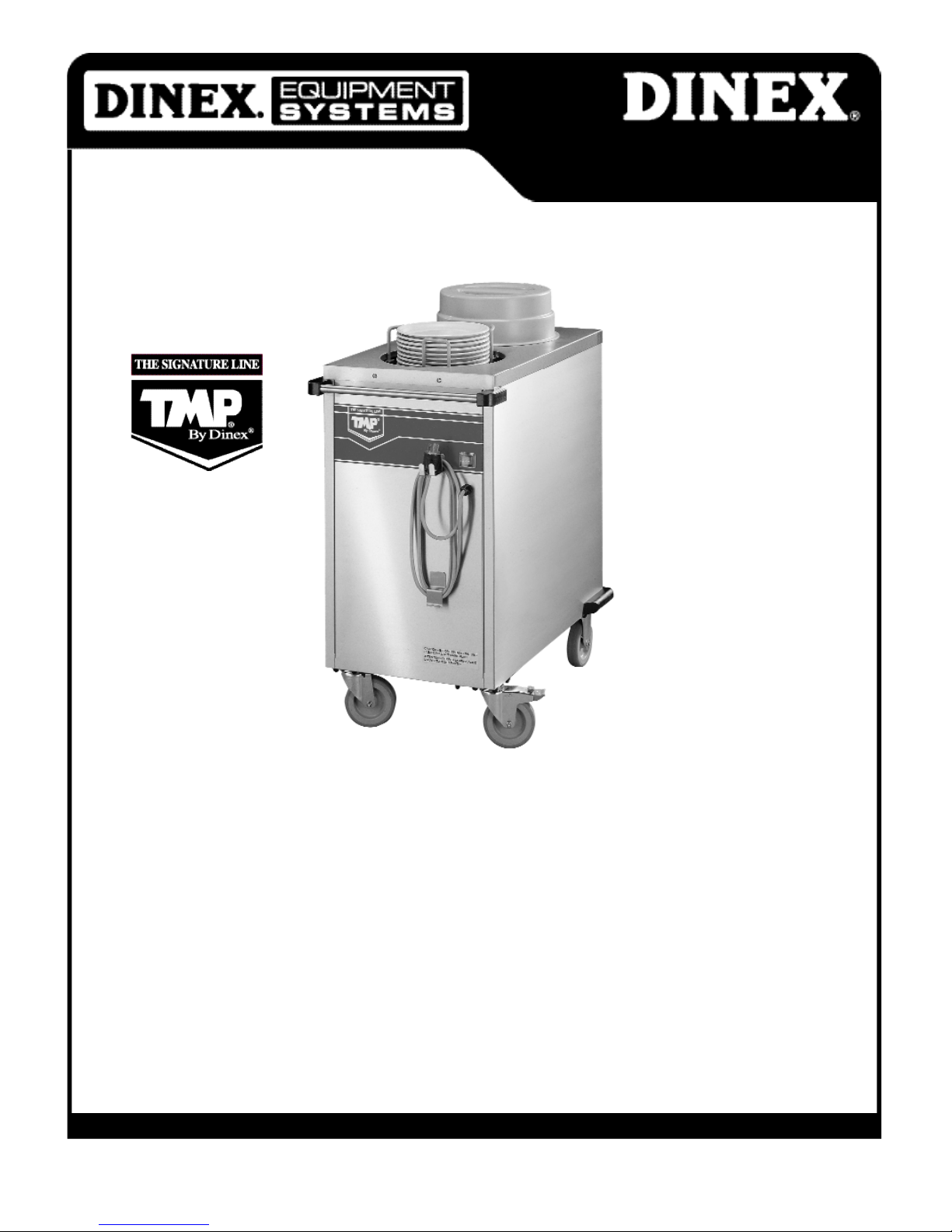
Model: TSH2
For Service Information, call 1-888-673-4639
Please provide following information:
• Model number
• Serial number
• Part Description and number as shown in parts list.
Manual No. TMP-PH Rev-03/06
Printed in the USA

Page 2
Introduction:
Installation:
You have purchased the new Dinex® TMP® Equipment.
Please read this manual for helpful guidelines on how to
use your Equipment. Should you have any questions
concerning the Equipment, please call the Dinex Hotline
at 1-888-673-4639 (Monday through Friday from 8 am to 5
pm, Eastern Standard Time).
IMPORTANT: For your safety, read and follow all cautions,
information and warnings
FREIGHT DAMAGE CLAIMS
Your Dinex Equipment was carefully inspected and packed
before leaving our plant.The transportation company
assumes full responsibility for the safe delivery of the
Equipment. Dinex does not assume any responsibility for
damage or loss incurred in transit. Please note any visible
damage or loss on the freight bill and have delivery personnel sign.
A freight claim should be filed immediately with the transportation company. If concealed damage is discovered
after unpacking the Equipment, please file a concealed
damage claim with the transport company within 10 days
after receipt of the goods.
IMPORTANT: All packing materials should be retained for
return shipment.
APPLICATION AND USE
The Equipment is for commercial use in the food service
industry. It provides storage of dishes and is operated
with a heating system.
SAFETY
The instructions contained in this manual provide important guidelines for the Equipment user regarding a correct
and safe installation. Particular attention should be paid to
the warnings given in various parts of this manual. Never
dismantle and/or repair the appliance with the power supply in place. Especially, do not repair electrical elements if
you are not qualified for such work.
INFO: Please note that this appliance is for commercial
use only and must be used exclusively for the purposes
prescribed.
SET UP
INFO: Installation of this Equipment should be performed
by persons qualified or licensed to install electrical
Equipment only. It is the responsibility of the installer to
comply with all local codes.
1. Carefully remove any packing material from the unit
and check loose packing material for small parts or
accessories. Inspect unit for concealed damage before
putting packing material aside.
2. Make sure that the master switch on the front panel of
the unit is in the “0” position. This controls the power
supply.
3.The unit operates at 240 V, 60 Hz, single phase.
Connect the unit by the plug with the main outlet.
4.Turn the master switch to the “I” position.The pilot light
will glow, indicating that it is ON, and the Equipment will
start to heat.
5. When heating cycle is completed, bring main switch into
O-position and remove the plug from the receptacle.
CAUTION: If excessive noise or vibration is noticed, turn
the master switch OFF and check the blower wheel for
freight damage or loose objects
INFO: Operation of this Equipment must be supervised.
The Dinex plate heater is designed to heat plates from
8 1/4 to 11 inches in diameter.
WARNING:The unit should not be operated continuously
24 hours a day. The master switch should be turned OFF
after serving the last meal of the day.
ADJUSTMENT OF SELF-LEVELING SILOS
IMPORTANT: Silo adustment not covered under warranty.
INFO: The spring adjustment must be performed with the
heating system switched OFF.
1. Place about 20 dishes, three to four at a time, onto the
dispenser platform. If the column goes down just a little
bit (or does not go down at all), remove the platform
and unhook the springs equally around the support.
2 . The co r re c t adjustment is when the dispensing level of
dish column is 2”(5cm) higher than the upper edge.Th e
u n h o o k ed springs remain inside the unit as spare spri n g s .
!
!
!
!
!
!
Operation Instructions:
!
!
!

Page 3
4. Use only one silo at a time. Keep the other silo covered.
Optional covers may be purchased separately.
THERMOSTAT SETTING
IMPORTANT: Thermostat adjustment not covered under
warranty.
CAUTION: Internal thermostat adjustment must be
performed by a Qualified Electrician.
The thermostat is pre-set at the highest temperature setting for the dispenser. If you find that the bases are too hot
for your application, reduce the temperature by turning
the thermostat knob to a lower setting. Since virtually all
facilities operate differently,the best way to determine
your optimal thermostat setting is to start with the pre-set
temperature, then adjust to determine the setting which
best suits your application.
The heaters in the unitized base are controlled by an
adjustable thermostat located behind the access panel
inside the unit.
1. Make sure that the master switch is in the “0” position
and remove the plug from the receptacle.
2. Remove the four screws on the access panel and remove
the panel.
3. The thermostat is located on the left-hand side, just
below the blower motor.
4. You can now change the thermostat setting while
pulling the knob into the desired adjustment.
5. Replace the panel, connect the unit with the main
outlet, switch on the unit and check the result of the
new setting.
INFO: Once the proper temperature setting is determined,
it is not necessary to reset the thermostat for every meal.
Leave the thermostat at the desired setting and turn the
unit ON and OFF using the master switch.
CAUTION: Prior to cleaning or maintenance work, turn
the master switch to the “0” position and disconnect the
power cord from the receptacle. The unit should be allowed
to cool first.
Dinex Equipment is constructed with high-quality materials and is designed to provide you with durable service
when treated with care. To obtain the best performance
from your Equipment, it should be cleaned daily and properly maintained.
FIELD-ADJUSTABLE BARS
The silo is equipped with adjustable bars, allowing the
adjustment of the plate guide to accommodate different
plate diameters. If you are not satisfied with the pre-set
diameter,you can lift the adjustable bar and place it into
the next perforation in the bottom plate of the silo.
LOADING OF PLATES
WARNING: Overfilling dispenser silos may cause injury
to operator or damage to the dispenser, thus voiding the
warranty.
1. To avoid bruised fingers or hand injuries, make sure the
dispensing level is 2” (5cm) higher than the upper
edge of the housing. (See Adjustment Of Self-Leveling
Silos on page 2)
2. Check to be sure that the plate guide is placed in the
supporting frame with the “feet extenders”side down.
Line up the plate guide with the supporting frame so
that the two nest together.
3. Each silo is designed for use with approx i m a tely 50 plate s ,
depending on plate thickness, material and design.
WARNING: Never drop stacks of plates into the silo
assembly.This can cause damage to the silo components
and void the warranty. Place three to four plates at a time
into the silo.
HEAT-UP TIMES
CAUTION: In spite of the housing insulation, temperatures
at the surface may be high. Never touch the unit without
using thermal protection gloves.
With cold plates (first meal of the day), the plates will reach
the pre-set final temperature after approximately 1-1/2 to
2 hours.
All times indicated are only approximate and may vary
depending on each facility’s operation,location of units
and supply voltage.
DISPENSING OF PLATES
WARNING: Severe burns may occur if instructions are not
followed.
1. Turn the master switch to “0”position and disconnect
electrical plug from the receptacle. Move the dispenser
to the start of the tray make-up line.
2. The operator must wear thermal protection gloves while
dispensing plates. Never touch plates with bare hands.
Never assume that plates are cool enough to be
handled with bare hands.
3. If a plate becomes jammed in the silo, do not reach into
the silo to free it — use a long stick instead.
!
!
!
!
!
Maintenance
!
!
!
 Loading...