

Dinel ULM-53, ULS-53 Instruction Manual
Before the rst use of the level meter please read carefully the instructions provided in this User's Guide
and keep it for future use. The manufacturer reserves the right to make changes without previous notice.
INSTRUCTION MANUAL
Ultrasonic level Meters UlM – 53
Ultrasonic level sensors Uls – 53


TABLE OF CONTENTS
1. Safety .......................................................................................................................................4
2. Packing, transportation and storage ....................................................................................4
3. Measuring principle ................................................................................................................5
4. Range of application ..............................................................................................................5
5. Features of variants ................................................................................................................5
6. Dimensional drawings ............................................................................................................6
7. Installation and putting into operation .................................................................................6
8. Installation instructions .........................................................................................................7
9. Electrical connection ............................................................................................................ 11
10. Set-up elements ....................................................................................................................14
11. Status indication ...................................................................................................................15
12. Setting ....................................................................................................................................16
12.1. Setting procedure for level meters ULM-53 .................................................................17
12.2. Setting procedure for level sensors ULS-53 ................................................................19
13. Protocol Modbus...................................................................................................................21
14. Order code .............................................................................................................................21
15. Accessories ...........................................................................................................................22
16. Safety, protection, compatibility and explosion proof design .........................................22
17. Use, operation and maintenance ........................................................................................23
18. General conditions and warranty ........................................................................................23
19. Marking of labels ..................................................................................................................24
20. Specications .......................................................................................................................25
UL_–53 © Dinel, s.r.o.
4
Any operations described in this User's Guide may only be performed by trained personnel or by an authorized person. Warranty and post-warranty repairs shall be performed
exclusively on the manufacturer's site.
Improper use, installation or setting of the level meter may lead to crashes in the application
(overlling of the tank or damage to system components).
The manufacturer is not responsible for improper use , work losses resulting from direct
or indirect damage and expenses incurred during installation or use of the level meter.
1 .
SAFETy
USEd SymBOLS
In order to provide maximum safety of processes, we have dened the following safety and information instructions. Each of the instructions is marked with an icon.
Alert, warning, danger
This symbol informs about particularly important instructions for installation and operation
of the equipment or about dangerous situations that may occur during installation and operation. Failure to comply with the instructions may cause failures, damage or destruction
of the equipment, or may cause injuries to persons.
Information
This symbol informs about particularly important characteristics of the equipment.
2 .
PACkAgiNg, TrANSPOrT ANd STOrAgE
The ULM–53 or ULS-53 device is packed in a cardboard packaging and the whole shipment is
placed in a cardboard box. The cardboard box is suitably lled to prevent mechanical damage during transport.
Remove the device from the package just prior to its use to prevent possible damage.
Transport to the customer is provided by a forwarding company. Subject to prior arrangement, personal pick-up of the ordered goods is possible in the company's seat. Upon receipt, please check
whether the shipment is complete and corresponds to the extent of the order, or whether during the
transport the packaging and the device has not been damaged. Do not use a device apparently
damaged during transport and contact the manufacturer to resolve the situation.
If the device is transported further, it shall be wrapped in the original packaging and protected
against shocks and weather.
Store the device in its original packaging in a dry place, sheltered from weather, with humidity up
to 85% without the effects of chemically active substances. The range of storage temperature is
-20°C to +60°C.
Level meters (sensors) of variants ULM (ULS)–53_–01, 02, 06, 10 are tted with protective caps
to prevent damage to the ultrasonic transducer. Remove the caps before commissioning!

5
© Dinel, s.r.o. UL_–53
3 .
mEASUriNg PriNCiPLE
The ULM® ultrasonic level meters and the ULS® ultrasonic level sensors are compact measurement devices containing an electro-acoustic transducer and an electronic module. Using the
electro-acoustic transducer, level meters and level sensors transmit a series of ultrasonic puls-
es that spread towards the surface. The transducer then receives the reected acoustic wave,
which is subsequently processed in the electronic module. The current distance to the surface
level is calculated from the time of spread of individual pulses towards the surface and back and
the temperature measured in the tank. The output is then set on the basis of the surface height.
The outputs of the ULM level meter are current 4 -20 mA, voltage 0 - 10 V and industrial line RS-485
with Modbus RTU communication. The output of the ULS sensor consists of a PNP transistor with
an open collector and a two-state current switch 4 mA / 20 mA.
4 .
rANgE OF APPLiCATiON
Thanks to the proximity principle employed, the devices are suitable for continuous or limit measurement of the level of liquids, waste water, sludge, suspensions, adhesives, resins in various open
and closed vessels, sumps, open channels and drains. Applicability for measuring the surface level
of loose materials is limited, the range of measurement is shorter there. Setting is carried out either
using two buttons or a magnetic pen or by remote setting in case of Modbus RTU output. The device
is equipped with optical indication of its state (RUN) and the setting process (STATE). It is manufactured in designs for normal (N) and explosive atmospheres (Xi).
UL_–53_–01–_ measurement range 0.1 m to 1 m, all-plastic design, source
of PVDF (polyvinylidene uoride), mechanical connection
with thread G ¾.
UL_–53_–02–_ measurement range 0.20 m to 2 m, all-plastic design, source of PVDF,
mechanical connection with thread G 1''.
UL_–53_–06–_ measurement range 0.20 m to 6 m, all-plastic design, source of PVDF,
mechanical connection with thread G 1 ½".
UL_–53_–10– measurement range 0.4 m to 10 m, all-plastic case, source of PVDF,
mechanical connection with thread G 2 ¼“.
UL_–53_–20–_ measurement range 0.5 m to 20 m, all-plastic case, source of PVDF,
mechanical connection with ange of aluminium alloy.
5 .
FEATUrES OF vAriANTS
UL_–53 © Dinel, s.r.o.
6
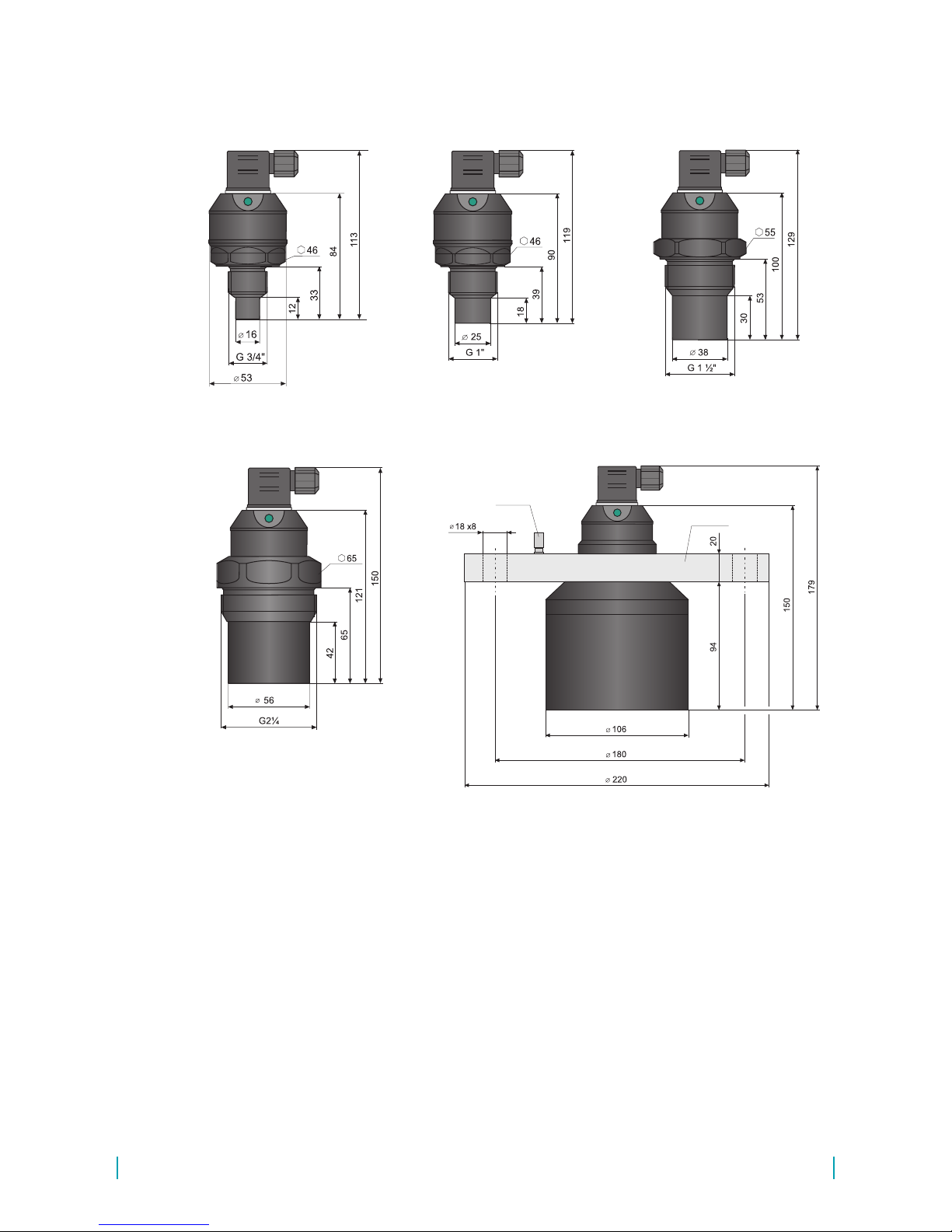
6 .
dimENSiONAL drAwiNgS
ground
terminal
UL_–53_–02–_
UL_–53_–06–_
UL_–53_–10–_
UL_–53_–20–_
Al alloy
This procedure includes the following three steps.
•
iNSTALLATiON
•
ELECTriC CONNECTiON
•
SETTiNg
7 .
iNSTALLATiON ANd PUTTiNg iNTO OPErATiON
UL_–53_–01–_
7
© Dinel, s.r.o. UL_–53
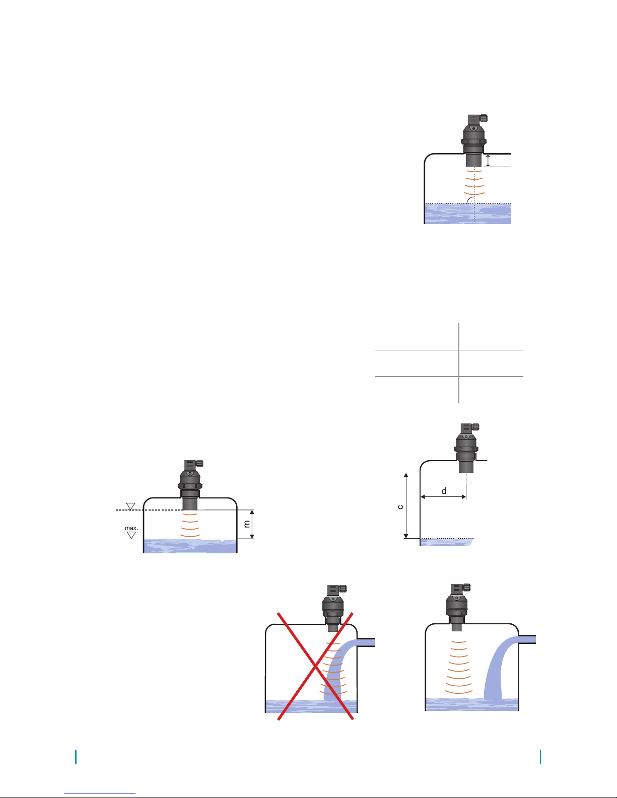
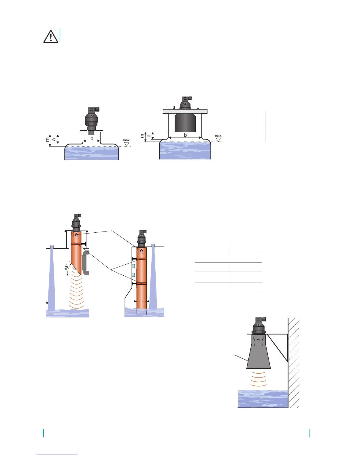
• The device is installed in a vertical position into the upper lid of the tank or reservoir using a
lug, a fastening nut or a ange in such a way that the axis of the device is perpendicular to the
surface level of the measured liquid (Fig. 1). Tightening
of the level meter in the welding ange (or. by the xing
nut) must be done only by hand *. The device shall be
installed in places with no risk of mechanical damage
to the front of the sensor.
• The minimum distance from the tank wall when installing
into the lid or the ceiling of the tank are listed in Fig. 3. In
the case of device installation close to smooth wall of the
tank it is not necessary to observe the minimum distance,
conversely it is suitable to shorten this distance.
• When installing in an open channel (sump, drain, etc.),
install the device onto a console as close as possible to
the expected maximum level.
• The reference plane for the measurement is the lower
edge of the transducer (Fig.2). In compliance with the
measuring principle, no signals reected in the area
directly below the device (dead zone) can be evaluated. The dead zone (Fig. 2) determines the minimum
distance possible between the device and the highest
level. The minimum distances to the medium are listed
in the chapter "Technical specications".
• The device shall be installed so that the surface does
not interfere with the dead zone when the tank is lled
to the maximum. If the measured surface interferes with
the dead zone, the device will not measure properly.
d – distance from tank wall
c – maximum reach of the device
m – dead zone
UL_–53–01 ; 02 ; 10
d > c/12
(min. 200 mm)
UL_–53–06
d > c/8
(min. 200 mm)
UL_–53–20
d > c/10
(min. 200 mm)
8 .
iNSTALLATiON iNSTrUCTiONS
Fig. 1: Correct installation of the sensor,
perpendicular to the liquid surface
Fig. 2: Dead zone of the device
Fig. 3: Distance of the device from
the tank wall
reference plane for
the measurement
*) To loosen the level meter can be used suitable wrenche.
Fig. 4: Installation of the device out of reach of lling circulation
• Do not install the device in or
above the lling point (Fig.
4). The measurement could
be affected by the inowing
medium.
min. 10 mm
UL_–53 © Dinel, s.r.o.
8
It is recommended to avoid placing the sensor into a narrow inlet.
UL_–53–01; 02;
06; 10
a < 1.5 b
b > 100 mm
UL_–53– 20
a < 1.5 b
b > 150 mm
Fig. 5: Installation of the device in the installation neck
!
• If the level sensor is mounted to bottlenecks and places with barriers, or near uneven walls or the
lling area, where the transmission signal could be distorted, we recommend using a guide tube
(acoustic horn). The tube must be made from a single material with a smooth inner surface (see
image 6 a 7). The minimum tube diameter must have the dimension „h“ according to see to table
at image 7. The construction of the guide tube we recommend to consult with the manufacturer.
Fig. 6: Short guide
tube installation
ventilation holes
sleeves for
mounting
h
Fig. 7: Total guide
tube installation
Fig. 8: Horn adapter installation
Horn
adapter ST
• Horn adapter ST–G0,75 (for ULM–53_–01), ST–G1 (for
ULM–53_–02), ST–G1,5 (for ULM–53_-06) or ST–G2,25
(for ULM–53_–10) for improved reception of the transmitted
signal can be used in open channels, sumps, tanks, etc.
• Horn adapter ST increases the directivity of the emitted
acoustic waves, improves the reception of weak echoes
(unstable surface level, loose materials, foam on the level)
and reduces the risk of falsereections.
• The horn adapter is installed on the device via process
connection G3/4“ (ST–G0,75) or G1” (ST–G1) or G1½”
(ST–G1,5), or G 2 ¼“ (ST–G2,25).
a – neck height from source edge
b – neck width
m – dead zone
UL_–53–01 h ≥ 50 mm
UL_–53–02 h ≥ 70 mm
UL_–53–06 h ≥ 100 mm
UL_–53–10 h ≥ 150 mm
UL_–53– 20 h ≥ 200 mm
• Only if the maximum level in the tank gets into the dead zone, the device shall be mounted into
a higher installation neck. The tank can be then lled nearly up to the maximum volume. The
neck’s inner surface shall be even and smooth (without edges and welded joints), the inner
edge should be rounded in the spot where the ultrasonic wave leaves the pipe. Choose the
largest possible neck diameter, but keep the neck height as low as possible. The recommended
dimensions of the inlet neck are listed in Fig. 5.

9
© Dinel, s.r.o. UL_–53
• The ultrasonic signal can be scattered or attenuated if the
surface is moderately stirred or rippled (due to a mixer, inow
of liquid, etc.). This may result in reduction of the measurement range or unreliable operation of the device (Fig. 11).
For a rippled or swirling level, you can use the directional
horn to eliminate scattering of the ultrasonic signal.
!
Fig. 11: Moderately stirred surface
• The site for installing the level meter needs to be chosen so that the emitted acoustic signal is not
affected by nearby objects (reinforcements, supports, brackets, ladders, heating elements, mixers,
etc.). These obstacles may result in false rebounds, increasing measurement inaccuracy (Fig. 9).
x – distance from the edge of the longest
object
c – maximum reach of the level meter
UL_–53–01 ;02 ; 10
x > c/12
(min. 200 mm)
UL_–53–06
x > c/8
(min. 200 mm)
UL_–53–20
x > c/10
(min. 200 mm)
Fig. 9: Minimum distance from close objects in the tank
• Foam may be produced on the surface of the measured liquid
during lling, mixing and other processes. The thick foam
signicantly absorbs the ultrasound signal and may cause
malfunction of the device (Fig.10). In those cases it is necessary to test the device in advance or contact the manufacturer .
In case of a thin layer of foam, it is also possible to use
directional horn for improving receipt of the reected echo.
!
Fig. 10: Thick foam on the surface
!
Fig. 12: Strongly stirred
surface
Fig. 13: False reection from
mixer blades
• The device should not be installed in places
with the risk of falsereections of the ultra-
sonic signal from the mixer’s blades (Fig. 13).
• False surface reections of the ultrasonic
signal and unreliable operation of the device
might result from the mixer’s rotating blades
that ripple the surface level(Fig. 12).
 Loading...