

Dinel ULM-70N-10-I, ULM-70Xi-10-I, ULM-70N-02-I, ULM-70N-06-I, ULM-70Xi-02-I Instruction Manual
...
INSTRUCTION MANUAL
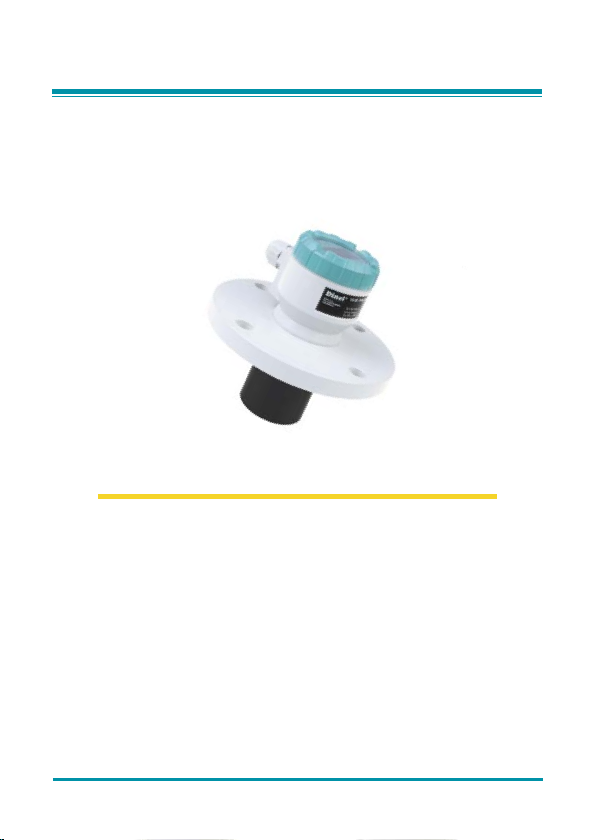
ULTRASONIC LEVEL METERS ULM–70
Read carefully the instructions published in this manual before the fi rst use of the level meters. Keep the manual
at a safe place. The manufacturer reserves the right to implement changes without prior notice.

CONTENTS
Safety ...............................................................................................................................................3
Measuring principle ..........................................................................................................................3
Range of application ........................................................................................................................3
Features of variants .........................................................................................................................3
Dimensional dr awings ....................................................................................................................4
Installation instructions ....................................................................................................................5
Electric al connection ......................................................................................................................8
Set-up elements ...............................................................................................................................9
Status signalizat ion ..........................................................................................................................9
Operation ....................................................................................................................................... 10
Basic settings .................................................................................................................................10
Advanced settings..........................................................................................................................13
Additional functions ........................................................................................................................15
HART communication protocol ......................................................................................................18
Order code .....................................................................................................................................18
Accessor ies....................................................................................................................................18
Safety, protection, compatibilit y and explosion proof ....................................................................19
Use, manipulation and maintenance .............................................................................................19
Marking of labels ............................................................................................................................20
Menu structure ...............................................................................................................................22
Technical specifi cations .................................................................................................................23
Area classifi cation ..........................................................................................................................24
Factory default ...............................................................................................................................24
久德電子
TEL :+886-4-23729418 FAX:+886-4-23724011
(40349)
台中市西區福人街11號
www.jetec.com.tw

SAFETY
All operatio ns described in this instr uction manual have to be carr ied out only by trained personn el
or an accredited person. Warrant y and post warranty service must be exclusively c arried out by
the manufacturer.
Improper use, in stallation or set-up of the leve l meter can result in crashes in the a pplication (overfi lling of the tank or damage of system components).
The manufacturer is not responsible for improper use, losses of work caused by either direct or
indirect damage, and for expenses incurred during installation or use of the level meter.
MEASURING PRINCIPLE
®
The ULM
ultrasonic leve l meters are compac t measurement device s including an elec troacoustic
converter and a n electronic modu le. Using the electro acoustic conver ter, the level meters transmit
the sequence of ultrasonic pulses that spread towards the surface level. The converter recuperates refl ected acoustic waves that are subsequently processed in the electronic module. The
intelligent evaluation block fi lters out interfering signals, compares the cleaned received signal
with the false refl e ction map (e.g. from mixers, ladder s, reinforcement etc.) and selects a s uitable
refl ection (echo). Based on the period during which the individual pulses spread towards the
surface level and back and based on the measured temperature in the tank, the instant distance
to the surfac e level is calculated. According to the level height, the level meter output is set and
the measured value is displayed on the display.
RANGE OF APPLICATIONS
For continuous no n-contact level measu rement of liquids (water solutions, sewe rage water, etc.),
mash and paste materials (sediments, sticks, resins etc.) in closed or open vessels, sumps,
reservoirs and open channels. In case the level of bulk-solid materials is measured, the measurement range is reduced.
The level meters c an continuously measure level s of bulk-solid materials with a low c oncentration
of dus
t particles. Consult the manufacturer on recommended use of the level meter for bulk-solid
materials.
FEATURES OF VAR IANT S
ULM –70_ –02–I Measuring range from 0.15m to 2m, plastic PVDF transmitter, mechanical
ULM –70_–06–I Measuring range from 0.25m to 6m, plastic PVDF transmitter, mechanical
ULM –70_–10–I Measuring range from 0.4m to 10m, plastic PVDF transmitter, mechanical
ULM–70_–20–I Measuring range from 0.5m to 20m, plastic PVDF transmitter, mechanical
connection with thread G 1".
connection with thread G 1 ½".
connection with HDPE polyethylene fl ange (version "N") or aluminium alloy
fl ange (version "Xi").
connection with aluminium alloy fl ange.
久德電子
TEL :+886-4-23729418 FAX:+886-4-23724011
(40349)
台中市西區福人街11號
www.jetec.com.tw
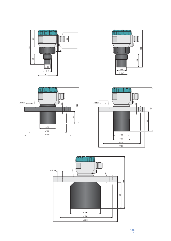
DIMENSIONAL DRAWINGS
ULM–70_–02–I
Pg11 cable gland
ULM–70_–06–I
Ground terminal
ULM–70N–10–I
HDPE
久德電子
TEL :+886-4-23729418 FAX:+886-4-23724011
Al alloy
ULM–70_–20–I
(40349)
ULM–70Xi–10–I
Al alloy
台中市西區福人街11號
www.jetec.com.tw
INSTALLATION INSTRUCTIONS
Install the level meter in the • vertic al positi on into the upper lid of the tank or reservoir using
a welding fl ange, a fastening nut or a fl ange so that the level meter axis can be perpendicular to
the surface level of the measured liquid (Fig. 1).
The min. • dimensional parameters to install the
level meter into a lid or a ceiling of a tank are given
in Fig. 3.
When installing in an • open channel (reservoir, drain
etc.), install the level meter onto a b racket as close as
possible to the expected max. level.
In connection with the measurement principle, no •
signals refl ected in the area immediately under the
level meter can be evaluated (dead zone). The dead
zone (Fig. 2) determines the min. distance possible
between the level meter and the highest surface level. The min. distances to the medium are given in the
chapter "Technical specifi cations" (p. 24).
It is necessary to install the level meter so that the •
bin level cannot inter fere with the dead zone when
fi lled up to the maximum. If the measured level interferes with the dead zone, the level meter will not
work properly.
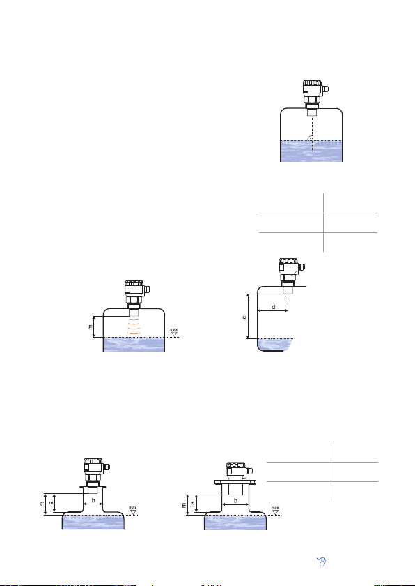
m – Dead zone
Fig. 1: Recommended installation
in the tank
ULM–70–02 ; 10
ULM–70–06
ULM–70–20
d > 1/12 c
(min. 200 mm)
d > 1/8 c
(min. 200 mm)
d > 1/10 c
(min. 200 mm)
d – Distance from
the tank wall
c – Measurement
range of the level
meter
Fig. 2: Level meter dead zone
If the maximum surface level in the tank interferes with the dead zone, the level meter has •
to be mounted into a higher inst allation neck. In this way, the tank can be fi lled nearly up to
the maximum volume. The inner neck surface has to be even and smooth (without edges and
welded joints); the inner edge should be rounded where the ultrasonic wave leaves the pipe.
The neck diameter should be as large as possible but the neck height should be as low as
possible. Recommended dimensions of the input neck are given in Fig. 4.
a – Neck height
b – Neck width
m – Dead zone
Fig. 4: Possible installation of the installation neck
久德電子
TEL :+886-4-23729418 FAX:+886-4-23724011
Fig. 3: Installation distance from the tank wall
ULM–70–02 ; 06
ULM–70–10
ULM–70–20
(40349)
台中市西區福人街11號
a < 3 b
b > 100 mm
a < 1,5 b
b > 100 mm
a < 1,5 b
b > 150 mm
www.jetec.com.tw
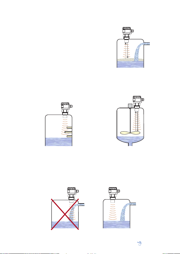
During fi lling, mixing and other processes, • foam
can arise on the surface level of the measured
liquid. The thick foam considerably absorbs the
ultrasonic signal which might cause malfunction
of the level meter (Fig. 5). For such cases, it is
necessar y to set up "SENSITIVITY " mode (p. 14)
to "high" or contact the manufacturer if need.
If the emitted ac oustic signal of the level meter •
is affected by near objects (roughness on walls
of the tank, various partitions, mixers etc.), it is
necessar y to map false refl ections by activating
the mode "TEACHING" (see p. 14). In case of installed mixers, it is necessary to put the mixers
to position under the level meter (direct the mixer
blade to the ultrasonic signal beam).
!
Fig. 5: Thick fo am on the surface
Fig. 6: False echo from obstacles in
Do not install the level meter in or above the • fi lling point (Fig. 8).
In case the level of bulk-solid materials is measured, the measurement range is reduced. We •
recommend to c onsult the use with the manufacturer.
久德電子
TEL :+886-4-23729418 FAX:+886-4-23724011
the tank
Fig. 8: Level meter installation outside the infl uence of fi lling
Fig. 7: False echo from the mixer blade
(40349)
台中市西區福人街11號
www.jetec.com.tw
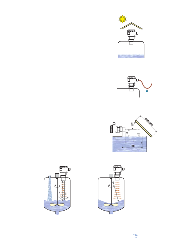
The level meter must not be installed in places •
with direct solar radiation and must be protected
against weather effects.
If the installation in places with direct solar ra-•
diation is inevitable, it is necessary to mount
a shieldin g cover above the level meter.
It is suitable to run the cable under a cable bush-•
ing (obliquely down in slack) according to Fig. 10
to prevent penetration of humidity. Then the
rain and condensing water can fl ow off freely.
The cable bushing and connector have to be • suf-
fi ciently tightened to prevent penetration of hu-
midity.
To lower the minimum distance to the measured •
medium, a refl ection board made from solid,
even and smooth material can be installed to the
level meter. Then the tank can be fi lled nearly up
to the maximum height. The solution is suitable
for open tanks and reservoirs.
Scattering or attenuation of the ultrasonic signal •
can result if the surface level has been moder-
ately sti rred or rippled (by a mixer, coming liquid etc.). It can result in reduction of the measurement range or unreliable function of the level
meter (Fig. 12).
Rotating mi xer blades c an cause• that the sur-
face is stirred, which results in false refl ections of
the ultrasonic signal from the surface level and
unreliable operation of the level meter (Fig. 13).
Fig. 9: Solar radiation shielding cover
Fig. 10: Prevention to avoid
intrusion of humidity
H + L = Dead zone
Fig. 11: Refl ection board
!
Fig. 12: Moderately stirred surface
久德電子
TEL :+886-4-23729418 FAX:+886-4-23724011
Fig. 13: Intensely stirred surface
(40349)
台中市西區福人街11號
www.jetec.com.tw
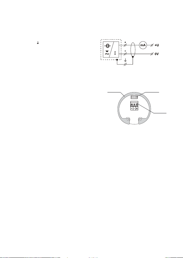
ELECTRICAL CONNECTION
The ultrasoni c level meter is designed to be connec ted to supply unit or to controller through a cable
with the outer diam eter of 6 ÷ 8 mm (recommend ed cross-section of c ores 0.5 ÷ 0.75 mm
of bolted clips p laced under display module. C onnect the plus pole (+U) to the termin al (+), the minus
pole to 0V to the terminal (-) and the shielding to
the terminal ( ) (only for shielded cables).
Procedure t o connect t he cable t o the level
meter:
Unscrew the nut of the upper transparent lid.1.
Take the upper edge of the displ ay module and 2.
take it out carefully by mild swinging up.
If you cannot grasp the module, you can use 3.
a small screwdriver. Insert it as far as the
seam and use from several sides to slightly
lift the module.
Release the cable bushing and thread the 4.
stripped supply cable in.
Connect the cable into the bolted clips according 5.
to the diagram in Fig. 14.
Assemble the level meter and connect the 6.
cable to the sequential unit.
Fig. 14: Connection diagram of the
level meter
Metal clip
Fig. 15: Internal view of terminal
Make the electric connection in voltage-free state!
The power supply can be a stabilized voltage supply unit of 18 ÷ 36V DC (version Xi - 30 V DC) that
is included in evaluation or display unit.
Considering possible occurrence of electrostatic charge on non-conducting parts of the level me-
, it is necessary to ground all level meters intended for environments with
ter
(ULM–70Xi–_ _–I). It will be done using a screw placed on the head of the level meter under the
cable bushing.
Display uni t
connector
block
risk of explosion
2
) by means
Term ina l
block

SET-UP ELEMENTS
Control buttons
Cable gland
Upper lid nut
OLED display
Fig. 16: Full view of ultrasonic level meter
utton Symbol in the man ual [OK
– Set-up mode access
– Confi rmation of selected item in the menu
– Move the cursor in the line
– Saving of set-up data
Button Symbol in the man ual
[ ↑ ↓ ]
– Move in the menu
– Change of values
Button Symbol in the man ual [ESC]
– Cancelling of carried out changes
– Shift one level up
STATUS SIGNALIZATION
display function
"NO ECHO"
"DEAD ZONE"
"NO PASSWORD"
symbol "T"
symbol "E"
1)
symbol appears in the lower left corner of the display
Lighting intermittently – the level meter is not able to re ceive echo
for a long time. Incorrec t installation of the level m eter
Lighting intermittently – the measured level is in th e "dead zone" of
the level meter or the ultrasonic convert er is dirty.
It will ap pear in the i tem "MENU" – the level m eter is protected
using a password against unaut horised setting. Enter t he correc t
password (see p. 17).
1)
Lighting permanently – "TEACHING" mode activation.
Lighting intermittently – correct echo rec eiving (of the refl ected
1)
signal) from t he measured surface l evel.
Ultrasonic transmitter
]
of measured values
mode activation
Label
Teaching
Display
Set-up elements
Echo receiving
Units
久德電子
TEL :+886-4-23729418 FAX:+886-4-23724011
(40349)
台中市西區福人街11號
www.jetec.com.tw

OPERATION
Set the level meter usin g 3 buttons placed on the displ ay module (see Chapter Set-up element s).
After 5 min. of inactivity, the level meter automatically returns back to the measurement mode.
If the password is active, the level meter will be also locked. The values that have not been
confi rmed using the button [OK] will not be saved! After the meter is locked, you cannot change
the setting! When you attempt to edit, the words "NO PASSWORD" will appear on the display.
How to unlock the level meter is given on page 17.
BASIC SETTINGS
Before the fi rst starting , you must carry out t he basic confi guration
of the level meter. The settings are accessible in the basic menu
under the item "BASIC ADJUSTMENT".
"AUTO MIN" (Automa tic sett ing of the 4m A limit)
After the mode is enabled, the actual measured level will be set as the min. level. The 4mA value
will be assigned to the level meter output. The setting is recommended only if the tank can be
fl ooded up to the required min. height.
ACTUAL LEVEL: Actual distance in mm
DISP: Display of measured values on the display
U: Unit selection (mm, cm, m, l, m
1. Fill up the tank up to the required level.
2. Press the button [OK] to access the basic menu. Use the same button to select the item "BASIC
ADJUSTMENT" and then "AUTO MIN".
3. Now the item "AUTO MIN" is displayed. The level meter assigns the 4mA value for the measured
value automatically.
4. Using the buttons [OK] and
units "U".
5. Af ter the setting is completed, save the data using the but ton [OK]. By repeated pressing the
button [ESC], you leave the menu and the display of the level meter and return back to the
measurement mode.
↑ ↓
]
[
, set the values to display on the display "DISP" and select the
"AUTO MAX" (Autom atic set ting of 20 mA l imit)
After the mo de is enabled, the actual measur ed level will be set as the max. level. Th e 20mA value
will be assigned to the level meter output. The setting is recommended only if the tank can be
fl ooded up to the required max. height.
3
,mA, %)
久德電子
TEL :+886-4-23729418 FAX:+886-4-23724011
ACTUAL LEVEL: Actual distance in mm
DISP: Display of measured values on the display
U: Unit selection (mm, cm, m, l, m
(40349)
台中市西區福人街11號
3
,mA, %)
www.jetec.com.tw

1. Fill up the tank up to the required level.
2. Press the button [OK] to access the basic menu. Use the same button to select the item "BASIC
ADJUSTMENT" and then use
3. Now the item "AUTO MA X" is displayed. The level meter as signs the 20mA value for the m easured
value automatically.
4. Using the buttons [OK] and
units "U".
5. After the setting is completed, save the data using the button [OK]. By repeated pressing the
button [ESC], you leave the menu and the display of the level meter and return back to the
measurement mode.
↑ ↓
]
[
and [OK] to select the item “AUTO MAX”.
↑ ↓
]
[
, set the values to display on the display "DISP" and select the
"MANUAL M IN and MANUAL M AX" (Ma nual sett ing of limit s)
In these items, you c an defi ne min. or max. level, to which you can assign an optional output current in
the range of 4
known but it is not possible to fl ood the tank up to these limits.
÷
20mA. This is recommended to carr y out if the fi nal value of the min. and max. level is
For convenience, it is suitable to assign 4mA current to the min. value and 2 0mA current to th e
max. value.
OUTPUT: Setting of output current (4 ÷ 20mA)
LEVEL: Setting of distance of the level from the
front of the level meter in mm
DISP: Display of measured values on the display
U: Unit selection (mm, cm, m, l, m
3
,mA, %)
1. Press the button [OK] to access the basic menu. Use the same button to select the item "BASIC
ADJUSTEMENT". Then use the button
"MANUAL MAX ".
2. Now the item "MANUAL MIN" or "MANUAL MA X" is displayed (as selected). Using the buttons
[OK]
[
↑ ↓
]
and
display of the value on the display "DISP" and unit selection "U".
3. After the setting is completed, save the data using the button [OK]. By repeated pressing the
button [ESC], you leave the menu and the display of the level meter and return back to the
measurement mode.
久德電子
TEL :+886-4-23729418 FAX:+886-4-23724011
, set the output cur rent "OUTPUT " and distance for the defi ned current "LEVEL",
↑ ↓
]
[
and [OK] to select the item "MANUAL MIN" or
(40349)
台中市西區福人街11號
www.jetec.com.tw

"DAMPING" (Sp eed of the me asuremen t response)
Setting of the speed of the measurement response. The function can be used to suppress deviations of the displayed values in case of quick or step changes of the level (e.g. stirred surface).
The response time of the subsequent measurement will be longer and the level meter will react to
quick changes with a defi ned delay.
The damping tim e can b e set in t he inte r val fr om
0 to 99 sec.
1. Press the button [OK] to access the basic menu. Use the same button to select the item "BASIC
ADJUSTEMENT". Then use the button
2. Now the item "DAMPING" is displayed. Using the buttons [OK] and
(0-99 sec.).
3. Af ter the setting is completed, save the data using the but ton [OK]. By repeated pressing the
button [ESC], you leave the menu and the display of the level meter and return back to the
measurement mode.
久德電子
TEL :+886-4-23729418 FAX:+886-4-23724011
↑ ↓
]
[
and [OK] to select the item "DAMPING".
(40349)
台中市西區福人街11號
↑ ↓
]
[
, set the damping time
www.jetec.com.tw

ADVANCED SETT INGS
In the supplemented c onfi guration, you can set parameters of
sensitivity, mapping of false refl ections, temperature difference
compensation, behaviour in case of fault conditions or HART
communicat ion. Here, you can set the sensor into th e initial state
or reset it as well.
The settings are accessible in the basic menu under the item "SERVICE".
"SENSITI VITY " (Level meter se nsitivi ty)
etting is defi ned in three steps of the level meter sensitivity.
The s
"low" – Low sensitivity in case of surrounding inter ferences af fecting the measurement.
"medium" – Medium sensitivity (suitable for most applications).
"high" –
High sensitivity for measured mediums par tly absorbing the ultrasonic signal (bulk-solid mat., foams)
You can set the sensitivity in three degrees:
"low", "medium" and "high".
"TEACHIN G" (Mapping o f false refl ecti
The mode serves for suppressing false refl ections resulting from refl ection of the ultrasonic
signal from roughnesses on walls of the tank, various partitions, mixers or other obstacles. The
sensor starting this mode detects false refl ec tions and save them in the memor y. The n these false
refl ections will not af fect the subsequent measurement (they are masked).
Before starting the mode, empty the tank under the level of the last obstacle in the tank.
[OK]
1. Press the button
"SERVICE" and press the button [OK]
and [OK] to select the item "TEACHING".
2. Now the item "TEACHING" is displayed. Press the button
– the expected distance of the sensor front from the medium surface level. If you do not know the
level distance exactly, set a smaller value (in the tolerance fi eld according to Fig. 17.).
3.
After the value of "LEVEL DISTANCE" is set, use the button [OK] to start the mode "TEACHING"
(mapping of false refl ections). During the mapping process, the word "RUNNING" is displayed
on the display.
4. The mapping of false refl ections is completed after the word "DONE" is displayed. Then you can
leave the menu by pressing the button [ESC].
久德電子
TEL :+886-4-23729418 FAX:+886-4-23724011
to access the basic menu. Press the button
ons)
If there are no above o bstacl es in the ta nk, it is
not necessary to start this mode
to confi rm. In the next menu use the buttons
[OK] to set the value
(40349)
台中市西區福人街11號
[ ↑ ↓ ] to select the item
"LEVEL DISTANCE"
[ ↑ ↓ ]
www.jetec.com.tw

Mapping of false refl ections lasts 5...30 sec.
according to the level meter type.
In case of installed mixers, it is necessary
to position the mixers under the level meter (direct the mixer blade to the ultrasonic
signal beam).
Note: If there are signifi cant obstacles in
the upper half of the tank, multiple false
refl ections can occur especially in closed
tanks. In such cases it is necessary to
reduce the level in the tank as much se
possible to correctly mask these possible
multiple false refl ections.
1/2 tank
Fig. 17: The "Level distance" zone
obstacles
Tolerance zone for "LEVEL
DISTANCE" value
"MEDIU M TEMPER ATURE" (Temperatu re compen sation)
If the temperature o f the measured substance (li quid) in the tank is differe nt from the temperature whe re
the level meter is installed (see the mode "DIAGNOSTICS", p. 17), it is necessary to compensate the
temperature because of accuracy of the measurement. Af ter the medium temperature is set, the level
meter calculates a n average value (from the medium temper ature and the temperature where th e level
meter is installed) and uses this average temperature for calculation of the level position.
Inactive compensation (initial state), the word
"NO" appears on the display.
"FAILURE MOD E" (Fault condi tions)
It defi nes the output current of the level meter when the measured medium level is in the dead
zone ("DEAD ZONE") or outside the measurement range in case of echo loss ("NO ECHO").
NO ECHO: Current in case of echo loss (3.75mA)
DEAD ZONE: Dead zone current (22mA)
The values can be s et in three steps - 3 .75mA,
22mA and LAST (last measured data).
久德電子
TEL :+886-4-23729418 FAX:+886-4-23724011
(40349)
台中市西區福人街11號
www.jetec.com.tw

"HART" (HART address setting)
HART mode (point to point, multidrop) and multidrop mode address setting. Up to 15 units can be
connected to one two-wired cable in the multidrop mode.
In case of the addr ess "00", the point to p oint
mode is enabled. The range from "01" to "15" is
reserved for addresses in the multidrop mode.
"FACTORY DEFAULT" (Default fac tory set ting)
et the initial values of the level meter set by the manufacturer, press the button [OK
To res
the Factory default table, p. 25)
After you pres s the button [OK], "RUNNING"
will be displayed fo r about 3 s ec. Af ter the i nitial
values are set, "DONE " will be appear on the
display.
] (see
"RESET" (L evel meter re start)
Complete restart of the level meter. The same effect has also a short-time interruption of the supply
voltage. To enable the resetting, press the button
[OK]
.
During the restart process, "RUNNING " will be
displayed. Then the l evel mete r will b e autom ati cally turned off and on.
久德電子
TEL :+886-4-23729418 FAX:+886-4-23724011
(40349)
台中市西區福人街11號
www.jetec.com.tw

ADDITIONAL FUNCT IONS
Additional functions include modes to display temperature in the tank or to fi nd out the actual
fl owing cur rent in the loop. Besid es, to lock modifi cations using a pas sword and information a bout
the level meter version. All of the functions are acc essible from the main menu.
"DIAGNOST ICS" (Diag nostic inf ormatio n)
It contains infor mation about the actual tempe rature inside the tank
(or about the compensated temperature) "TEMPER ATURE" and
current fl owing through the loop "CURRENT". If the temperature
compensation ("MEDIUM TEMPERATURE") is activated, the
corrected temperature is displayed.
The temperature is measured inside the tank where
the level meter is installed.
If the temperature of the measured medium is different, we recommen d you to carr y out the tem perature compensation "MEDIUM TEMPERATURE"
because of accuracy (see p. 15). Then the displayed
temperature is an ave rag e value f ro m the te mpe ra ture set in the "M ED IU M T EM PERATURE" and the
actual temperature measured by the sensor.
"PASSWORD " (Lock t he level mete r)
You can set any digital combination to lock the level meter and prevent an unauthorised person
from setting.
1.
Use the buttons [OK] and
entering the password or the mode "CHANGE" for changing the password (when activated,
the words are displayed inversely). Press the button [OK] once again to confi rm the selection.
You can change the password only when the level meter is unlocked. Otherwise, the words
"NO PASSWORD" will be displayed.
2
. Now you can edit the password. The actual edited item is displayed inversely. Press the button
[OK]
to move to the next position (clockwise direction); the button
values (0 ... 9).
3
. After the operation is completed, confi rm the edited data by pressing the button [OK].
[ ↑ ↓ ]
in the menu "PASSWORD" to select the mode "ENTER" for
[ ↑ ↓ ]
serves to change the
久德電子
TEL :+886-4-23729418 FAX:+886-4-23724011
Display of status information to confi rm data:
"YES" – correctly edited password
"NO" – incorrectly edited password
"OK" – the passw. saved (only in case of "CHANGE")
The password is automatically hidden after it is
edited or changed ("00000" will appear).
To deactivate the password, edit the numerical
combination "00000" in the mode "CHANGE".
If the password is lost, contact the manufacturer.
(40349)
台中市西區福人街11號
www.jetec.com.tw

"INFO" – (Type da ta)
Information about the type, serial number and production date of the level meter.
ST: Level meter type
SN: Serial number
SW: Firmware version
久德電子
TEL :+886-4-23729418 FAX:+886-4-23724011
(40349)
台中市西區福人街11號
www.jetec.com.tw

HART COMMUNICATION PROTOCOL
Universal communication interface for data communication of peripheral devices with the level
meter. Data transmission runs through the same line as the 4 ÷ 20 mA current loop without impact
on analog communication.
ULM–70
≈ 250 R
Voltage supply unit
HART
HART
communicator
Fig. 18: Typical PLC/mA confi guration with HART
modem
USB / RS232
ORDER CODE
–
ULM – 70
–
Output type:
Maximum range:
Performance:
I - Current
02 - 0.15 ... 2 m
06 - 0.25 ... 6 m
10 - 0.4 ... 10 m
20 - 0.5 ... 20 m
N - Normal - usable in non-explosive areas only
Xi - Ex. proof - suitable for explosive areas
ACCESSORIES
Standard – included in the price of the level meter Optional – for extra charge
• 1x Seal (only for ULM–70_–02–I, 06–I) • Stainless fi xing nut UM–G1''
久德電子
TEL :+886-4-23729418 FAX:+886-4-23724011
(40349)
(for ULM–70_–02–I)
• Stainless fi xing nut UM–G1½''
(for ULM–70_–06–I)
台中市西區福人街11號
PC
www.jetec.com.tw

SAFETY, PROTECTION, COMPATIBILITY AND EXPLOSION PROOF
The level meter ULM –70 is equipped with protection against reverse polarity and output current
overload.
Protection against dangerous contact is secured by low safety voltage that complies with
EN 33 2000-4-41.
Electromagnetic compatibility according to EN 55022/B, EN 61326/Z1 and EN 61000-4-2 to 6.
Explosion proof of ULM–70Xi type complies with the following standards: EN 60079-0 : 2007;
EN 60079-11 : 2007 ; EN 60079-26 : 2007 and examined by FTZÚ-AO 210 Ostrava - Radvanice
certifi cate No.: FTZÚ 09 ATEX 0277X.
USE, MANIPULATION AND MAINTENANCE
The level meter does not require any personnel for its operation. Follow-up displaying device is
used to inform the technological entity operating personnel on the measured substance level
height during the operation.
Maintenance of this equipment consists in verifi cation of integrity of the level meter and of the
supply cable. Depending on the character of the substance measured, we recommend to verify at
least once per year the clarit y of the ultrasound transducer emitting fi eld and to clean it, respec -
tively. In case any visible defects are discovered, the manufacturer or reseller of this equipment
must be contacted immediately.
It is forbidden to perform any modifi cations or inter ventions into the ULM–70 level meter without
manufac turer's approval. Potential repairs must be carried out by the manufacturer or by a manufacturer authorized service organization only.
Installation, c ommissioning, operation and maintenance of the ULM–70 level meter has to be carried out in acc ordance with this instr uction manual; the provisi ons of regulations in force re garding
the installation of electrical equipment have to be adhered to.
久德電子
TEL :+886-4-23729418 FAX:+886-4-23724011
(40349)
台中市西區福人街11號
www.jetec.com.tw

MARKING OF LABELS
Level meters label data
ULM–70N– 02–I and ULM–70N– 06–I:
Symbol of producer: logo Dinel•
Level meter type:•
Serial number: Ser. No.: xxxxx - (from the left: production year, serial production number)•
Supply voltage: U•
Output current range: I•
Ambient temperature range: t•
Protection class: IP67•
Compliance mark: •
Electro-waste take-back system mark: •
Level meters label data
ULM–70N–10–I and ULM–70N–20 –I:
Symbol of producer: logo Dinel•
Level meter type: •
Serial number: Ser. No.: xxxxx - (from the left: production year, serial production number)•
Supply voltage: U•
Output current range: I•
Ambient temperature range: t•
Protection class: IP67•
Compliance mark: •
Electro-waste take-back system mark: •
Level meters label data
ULM–70Xi–02– I and ULM–70Xi– 06–I:
Symbol of producer: logo Dinel•
Level meter type:•
Serial number: Ser. No.: xxxxx - (from the left: production year, serial production number)•
Output current range: I•
Limit operating parameters:• U
Ambient temperature range for the zone• 0: t
Ambient temperature range• : t
Label of non-explosive device• : ; Performance: II 1/2G Ex ia IIB T5
Number of cer tifi cate of intrinsically safety• : FTZÚ 09 ATEX 0277X
Protection class: IP67•
Compliance mark•
Electro-waste take-back system mark:•
ULM–70N–02–I, ULM–70N–06–I
= 18 ÷ 36 V =
i
ULM–70N–10–I, ULM–70N–20–I
= 18 ... 36 V =
i
ULM–70Xi–02–I, ULM–70Xi–06–I
: ,
®
= 4 ÷ 20 mA
= -30 ... +70°C
a
®
= 4 ÷ 20 mA
= -30 ... +60°C
a
®
= 4 ÷ 20 mA
= 30 V =, Ii = 132 mA; Pi = 0,99 W; Ci = 370 nF; Li = 0,9 mH
i
= -30 ... +70°C
a
= -20 to +60°C
a
No. of authorized person examining control of system quality:1026
久德電子
TEL :+886-4-23729418 FAX:+886-4-23724011
(40349)
台中市西區福人街11號
www.jetec.com.tw

Level meters label data
ULM–70Xi–10–I:
Symbol of producer: logo Dinel•
Level meter type:•
Serial number: Ser. No.: xxxxx - (from the left: production year, serial production number)•
Output current range: I•
Limit operating parameters:• U
Ambient temperature range for the zone• 0: t
Ambient temperature range• : t
Label of non-explosive device• : ; Performance: II 1/2G Ex ia IIA T5
Number of cer tifi cate of intrinsically safety• : FTZÚ 09 ATEX 0277X
Protection class: IP67•
Compliance mark•
Electro-waste take-back system mark:•
Level meters label data
ULM–70Xi–20–I:
Symbol of producer: logo Dinel•
Level meter type:•
Serial number: Ser. No.: xxxxx - (from the left: production year, serial production number)•
Output current range: I•
Limit operating parameters:• U
Ambient temperature range for the zone• 1: t
Ambient temperature range• : t
Label of non-explosive device• : ; Performance: II 2G Ex ia IIA T5
Number of cer tifi cate of intrinsically safety• : FTZÚ 09 ATEX 0277X
Protection class: IP67•
Compliance mark•
Electro-waste take-back system mark:•
Note: Real labe l size is 70x20mm .
ULM–70Xi–10–I
: ,
ULM–70Xi–20–I
: ,
®
= 4 ÷ 20 mA
= 30 V =, Ii = 132 mA; Pi = 0,99 W; Ci = 370 nF; Li = 0,9 mH
i
= -30 ... +60°C
a
= -20 to +60°C
a
No. of authorized person examining control of system quality:1026
®
= 4 ÷ 20 mA
= 30 V =, Ii = 132 mA; Pi = 0,99 W; Ci = 370 nF; Li = 0,9 mH
i
= -30 ... +60°C
a
= -20 to +60°C
a
No. of authorized person examining control of system quality:1026
久德電子
TEL :+886-4-23729418 FAX:+886-4-23724011
(40349)
台中市西區福人街11號
www.jetec.com.tw

MENU STRUCTURE
久德電子
TEL :+886-4-23729418 FAX:+886-4-23724011
(40349)
台中市西區福人街11號
www.jetec.com.tw

TECHNICAL SPECIFICATIONS
ULM–70_–02–I
ULM–70_–06–I
Measuring range
Supply voltage
1)
ULM–70_–10–I
ULM–70_–20–I
ULM–70N–_ _–I
ULM–70Xi–_ _–I
Output 4 ... 20 mA
Resolution < 1 mm
Accuracy (within the total range) 0.15 %
Temperature error max. 0.04% /
Beamwidth (-3 dB)
Ambient temperature range
ULM–70_–02; 10–I
ULM–70_–06–I
ULM–70_–20–I
ULM–70_–02 ; 06–I
ULM–70_–10 ; 20–I
Short-time temperature stress resistance
Max. operation overpressure (on transmission surface) 0.1
Sensitivity 3 st eps (low – medium – high)
Damping 0 ... 99 sec.
Measuring period 1 ... 4 sec.
Data between power supply rise time and full emission output 30 sec.
Additional technical data
2)
(only for variant Xi) –
Max. internal values
Ui=30V DC; Ii=132mA; Pi=0.99W; Ci=370nF; Li=0.9mH
Failure indication (echo loss, level in dead zone, internal failure)
Protection class IP67
ULM–70_–02–I
Mechanical connection
ULM–70_–06–I
ULM–70N–10–I
ULM–70Xi–10–I
ULM–70_–20–I
Recommended cable PVC 2 x 0.75 mm
Current output load resistance (U = 24 V DC) R
ULM–70_–02–I
Weight
1)
In case the level of bulk-solid materials is measured, the measurement range is reduced.
2)
Allowed temperature range in the zone 0: -20°C ... +60°C; allowed pressure range in the zone 0: 80 ... 110 kPa.
3)
Including 250R resistor in case of HART connection.
ULM–70_–06–I
ULM–70N–10–I
ULM–70Xi–10–I
ULM–70_–20–I
0.15 ... 2 m
0.25 ... 6 m
0.4 ... 10 m
0.5 ... 20 m
DC
18 ... 36 V
18 ... 30 V DC
(limit values 3.9 ... 20.5 mA), HART
K
10°
14°
12°
-30 ... +70°C
-30 ... +60°C
+90°C / 1 hour
MPa
Adjustable in modes:
3.75 mA ; 22 mA ; last measured value
screwing with thread G 1''
screwing with thread G 1½''
HDPE fl ange
aluminium alloy fl ange
aluminium alloy fl ange
2
(3 x 0.5 mm2)
3)
= 270 Ω
max
0.3 kg
0.4 kg
0.7 kg
1.2 kg
3.1 kg
久德電子
TEL :+886-4-23729418 FAX:+886-4-23724011
(40349)
台中市西區福人街11號
www.jetec.com.tw

AREA CLASSIFICATION (according to EN 60079-10 and EN 60079-14)
ULM–70N–_ _–I
ULM–70Xi–02–I
ULM–70Xi–06–I
ULM–70Xi–10–I
ULM–70Xi–20–I
Explosive proof – suitable for explosive areas (combustible gases or vapours)
Explosive proof – suitable for explosive areas (combustible gases or vapours)
Explosive proof – suitable for explosive areas (combustible gases or vapours)
Performance for non-explosive areas
II 1/2G Ex ia IIB T5 with isolating repeater (IRU–420),
the whole level meter – zone 1, front head part – zone 0
II 1/2G Ex ia IIA T5 with isolating repeater (IRU–420),
the whole level meter – zone 1, front head part – zone 0
II 2G Ex ia IIA T5 with isolating repeater (IRU–420),
the whole level meter – zone 1
FACTORY DEFAULT
LEVEL MIN 150 250 400 500
LEVEL MAX 2000 6000 10000 20000
DAMPING 2 5 10 10
SENSITIVITY MEDIUM MEDIUM MEDIUM MEDIUM
MEDIUM TEMPERATURE NO NO NO NO
FAILURE MODE – NO ECHO 3,75 mA 3,75 mA 3,75 mA 3,75 mA
FAILURE MODE – DEAD ZONE 22 mA 22 mA 22 mA 22 mA
POOLING ADDRESS (HART) 00 00 00 00
PASSWORD no password no password no password no password
久德電子
TEL :+886-4-23729418 FAX:+886-4-23724011
ULM–70_–02 ULM–70_–06 ULM–70_–10 ULM–70_–20
(40349)
台中市西區福人街11號
www.jetec.com.tw
 Loading...