

Dinel ULM-70N-10-I, ULM-70Xi-10-I, ULM-70N-02-I, ULM-70N-06-I, ULM-70Xi-02-I Instruction Manual
...
INSTRUCTION MANUAL
ULTRASONIC LEVEL METERS ULM–70
Read carefully the instructions published in this manual before the fi rst use of the level meters. Keep the manual
at a safe place. The manufacturer reserves the right to implement changes without prior notice.

CONTENTS
Safety ...............................................................................................................................................3
Measuring principle ..........................................................................................................................3
Range of application ........................................................................................................................3
Features of variants .........................................................................................................................3
Dimensional dr awings ....................................................................................................................4
Installation instructions ....................................................................................................................5
Electric al connection ......................................................................................................................8
Set-up elements ...............................................................................................................................9
Status signalizat ion ..........................................................................................................................9
Operation ....................................................................................................................................... 10
Basic settings .................................................................................................................................10
Advanced settings..........................................................................................................................13
Additional functions ........................................................................................................................15
HART communication protocol ......................................................................................................18
Order code .....................................................................................................................................18
Accessor ies....................................................................................................................................18
Safety, protection, compatibilit y and explosion proof ....................................................................19
Use, manipulation and maintenance .............................................................................................19
Marking of labels ............................................................................................................................20
Menu structure ...............................................................................................................................22
Technical specifi cations .................................................................................................................23
Area classifi cation ..........................................................................................................................24
Factory default ...............................................................................................................................24
久德電子
TEL :+886-4-23729418 FAX:+886-4-23724011
(40349)
台中市西區福人街11號
www.jetec.com.tw

SAFETY
All operatio ns described in this instr uction manual have to be carr ied out only by trained personn el
or an accredited person. Warrant y and post warranty service must be exclusively c arried out by
the manufacturer.
Improper use, in stallation or set-up of the leve l meter can result in crashes in the a pplication (overfi lling of the tank or damage of system components).
The manufacturer is not responsible for improper use, losses of work caused by either direct or
indirect damage, and for expenses incurred during installation or use of the level meter.
MEASURING PRINCIPLE
®
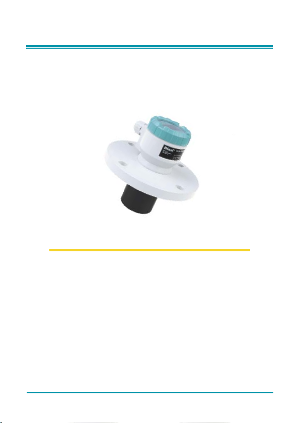
The ULM
ultrasonic leve l meters are compac t measurement device s including an elec troacoustic
converter and a n electronic modu le. Using the electro acoustic conver ter, the level meters transmit
the sequence of ultrasonic pulses that spread towards the surface level. The converter recuperates refl ected acoustic waves that are subsequently processed in the electronic module. The
intelligent evaluation block fi lters out interfering signals, compares the cleaned received signal
with the false refl e ction map (e.g. from mixers, ladder s, reinforcement etc.) and selects a s uitable
refl ection (echo). Based on the period during which the individual pulses spread towards the
surface level and back and based on the measured temperature in the tank, the instant distance
to the surfac e level is calculated. According to the level height, the level meter output is set and
the measured value is displayed on the display.
RANGE OF APPLICATIONS
For continuous no n-contact level measu rement of liquids (water solutions, sewe rage water, etc.),
mash and paste materials (sediments, sticks, resins etc.) in closed or open vessels, sumps,
reservoirs and open channels. In case the level of bulk-solid materials is measured, the measurement range is reduced.
The level meters c an continuously measure level s of bulk-solid materials with a low c oncentration
of dus
t particles. Consult the manufacturer on recommended use of the level meter for bulk-solid
materials.
FEATURES OF VAR IANT S
ULM –70_ –02–I Measuring range from 0.15m to 2m, plastic PVDF transmitter, mechanical
ULM –70_–06–I Measuring range from 0.25m to 6m, plastic PVDF transmitter, mechanical
ULM –70_–10–I Measuring range from 0.4m to 10m, plastic PVDF transmitter, mechanical
ULM–70_–20–I Measuring range from 0.5m to 20m, plastic PVDF transmitter, mechanical
connection with thread G 1".
connection with thread G 1 ½".
connection with HDPE polyethylene fl ange (version "N") or aluminium alloy
fl ange (version "Xi").
connection with aluminium alloy fl ange.
久德電子
TEL :+886-4-23729418 FAX:+886-4-23724011
(40349)
台中市西區福人街11號
www.jetec.com.tw
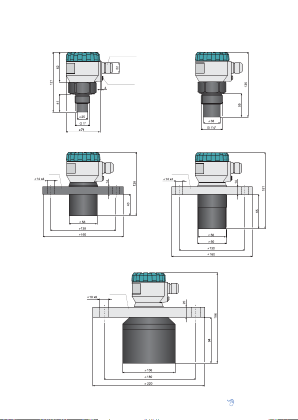
DIMENSIONAL DRAWINGS
ULM–70_–02–I
Pg11 cable gland
ULM–70_–06–I
Ground terminal
ULM–70N–10–I
HDPE
久德電子
TEL :+886-4-23729418 FAX:+886-4-23724011
Al alloy
ULM–70_–20–I
(40349)
ULM–70Xi–10–I
Al alloy
台中市西區福人街11號
www.jetec.com.tw
INSTALLATION INSTRUCTIONS
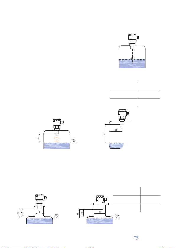
Install the level meter in the • vertic al positi on into the upper lid of the tank or reservoir using
a welding fl ange, a fastening nut or a fl ange so that the level meter axis can be perpendicular to
the surface level of the measured liquid (Fig. 1).
The min. • dimensional parameters to install the
level meter into a lid or a ceiling of a tank are given
in Fig. 3.
When installing in an • open channel (reservoir, drain
etc.), install the level meter onto a b racket as close as
possible to the expected max. level.
In connection with the measurement principle, no •
signals refl ected in the area immediately under the
level meter can be evaluated (dead zone). The dead
zone (Fig. 2) determines the min. distance possible
between the level meter and the highest surface level. The min. distances to the medium are given in the
chapter "Technical specifi cations" (p. 24).
It is necessary to install the level meter so that the •
bin level cannot inter fere with the dead zone when
fi lled up to the maximum. If the measured level interferes with the dead zone, the level meter will not
work properly.
m – Dead zone
Fig. 1: Recommended installation
in the tank
ULM–70–02 ; 10
ULM–70–06
ULM–70–20
d > 1/12 c
(min. 200 mm)
d > 1/8 c
(min. 200 mm)
d > 1/10 c
(min. 200 mm)
d – Distance from
the tank wall
c – Measurement
range of the level
meter
Fig. 2: Level meter dead zone
If the maximum surface level in the tank interferes with the dead zone, the level meter has •
to be mounted into a higher inst allation neck. In this way, the tank can be fi lled nearly up to
the maximum volume. The inner neck surface has to be even and smooth (without edges and
welded joints); the inner edge should be rounded where the ultrasonic wave leaves the pipe.
The neck diameter should be as large as possible but the neck height should be as low as
possible. Recommended dimensions of the input neck are given in Fig. 4.
a – Neck height
b – Neck width
m – Dead zone
Fig. 4: Possible installation of the installation neck
久德電子
TEL :+886-4-23729418 FAX:+886-4-23724011
Fig. 3: Installation distance from the tank wall
ULM–70–02 ; 06
ULM–70–10
ULM–70–20
(40349)
台中市西區福人街11號
a < 3 b
b > 100 mm
a < 1,5 b
b > 100 mm
a < 1,5 b
b > 150 mm
www.jetec.com.tw
During fi lling, mixing and other processes, • foam
can arise on the surface level of the measured
liquid. The thick foam considerably absorbs the
ultrasonic signal which might cause malfunction
of the level meter (Fig. 5). For such cases, it is
necessar y to set up "SENSITIVITY " mode (p. 14)
to "high" or contact the manufacturer if need.
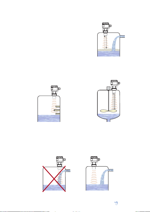
If the emitted ac oustic signal of the level meter •
is affected by near objects (roughness on walls
of the tank, various partitions, mixers etc.), it is
necessar y to map false refl ections by activating
the mode "TEACHING" (see p. 14). In case of installed mixers, it is necessary to put the mixers
to position under the level meter (direct the mixer
blade to the ultrasonic signal beam).
!
Fig. 5: Thick fo am on the surface
Fig. 6: False echo from obstacles in
Do not install the level meter in or above the • fi lling point (Fig. 8).
In case the level of bulk-solid materials is measured, the measurement range is reduced. We •
recommend to c onsult the use with the manufacturer.
久德電子
TEL :+886-4-23729418 FAX:+886-4-23724011
the tank
Fig. 8: Level meter installation outside the infl uence of fi lling
Fig. 7: False echo from the mixer blade
(40349)
台中市西區福人街11號
www.jetec.com.tw
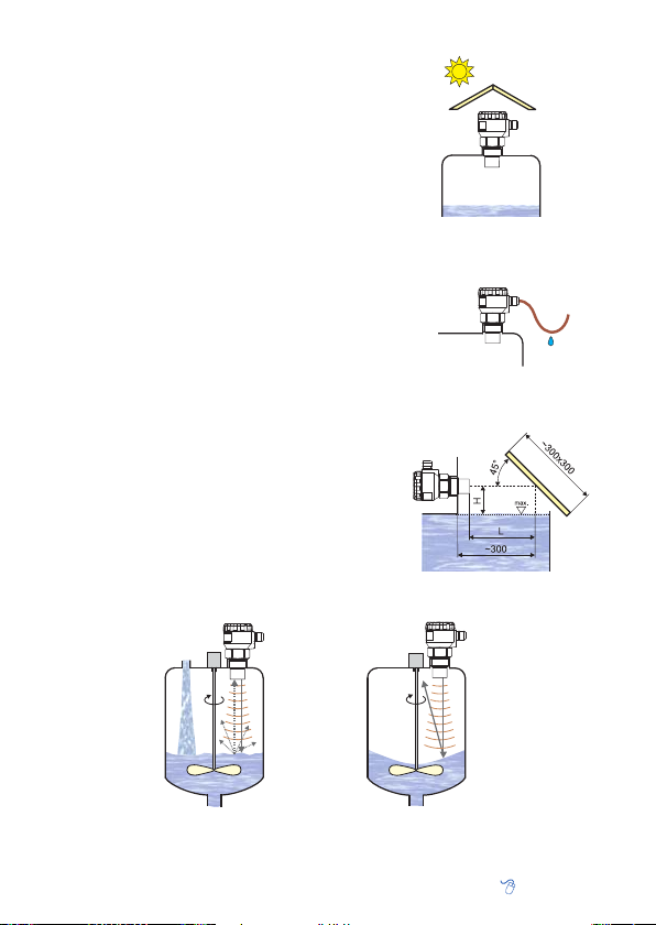
The level meter must not be installed in places •
with direct solar radiation and must be protected
against weather effects.
If the installation in places with direct solar ra-•
diation is inevitable, it is necessary to mount
a shieldin g cover above the level meter.
It is suitable to run the cable under a cable bush-•
ing (obliquely down in slack) according to Fig. 10
to prevent penetration of humidity. Then the
rain and condensing water can fl ow off freely.
The cable bushing and connector have to be • suf-
fi ciently tightened to prevent penetration of hu-
midity.
To lower the minimum distance to the measured •
medium, a refl ection board made from solid,
even and smooth material can be installed to the
level meter. Then the tank can be fi lled nearly up
to the maximum height. The solution is suitable
for open tanks and reservoirs.
Scattering or attenuation of the ultrasonic signal •
can result if the surface level has been moder-
ately sti rred or rippled (by a mixer, coming liquid etc.). It can result in reduction of the measurement range or unreliable function of the level
meter (Fig. 12).
Rotating mi xer blades c an cause• that the sur-
face is stirred, which results in false refl ections of
the ultrasonic signal from the surface level and
unreliable operation of the level meter (Fig. 13).
Fig. 9: Solar radiation shielding cover
Fig. 10: Prevention to avoid
intrusion of humidity
H + L = Dead zone
Fig. 11: Refl ection board
!
Fig. 12: Moderately stirred surface
久德電子
TEL :+886-4-23729418 FAX:+886-4-23724011
Fig. 13: Intensely stirred surface
(40349)
台中市西區福人街11號
www.jetec.com.tw
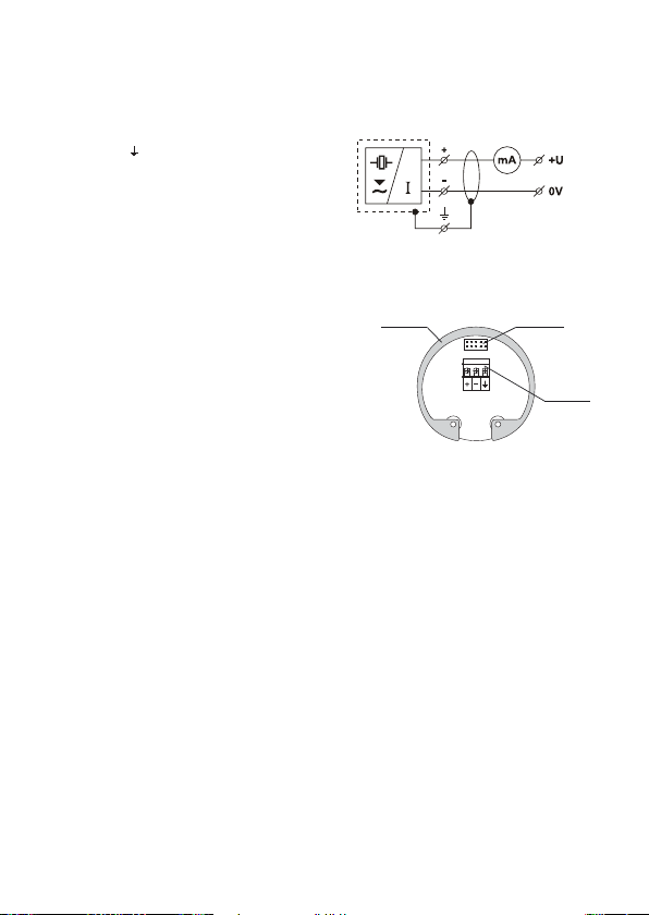
ELECTRICAL CONNECTION
The ultrasoni c level meter is designed to be connec ted to supply unit or to controller through a cable
with the outer diam eter of 6 ÷ 8 mm (recommend ed cross-section of c ores 0.5 ÷ 0.75 mm
of bolted clips p laced under display module. C onnect the plus pole (+U) to the termin al (+), the minus
pole to 0V to the terminal (-) and the shielding to
the terminal ( ) (only for shielded cables).
Procedure t o connect t he cable t o the level
meter:
Unscrew the nut of the upper transparent lid.1.
Take the upper edge of the displ ay module and 2.
take it out carefully by mild swinging up.
If you cannot grasp the module, you can use 3.
a small screwdriver. Insert it as far as the
seam and use from several sides to slightly
lift the module.
Release the cable bushing and thread the 4.
stripped supply cable in.
Connect the cable into the bolted clips according 5.
to the diagram in Fig. 14.
Assemble the level meter and connect the 6.
cable to the sequential unit.
Fig. 14: Connection diagram of the
level meter
Metal clip
Fig. 15: Internal view of terminal
Make the electric connection in voltage-free state!
The power supply can be a stabilized voltage supply unit of 18 ÷ 36V DC (version Xi - 30 V DC) that
is included in evaluation or display unit.
Considering possible occurrence of electrostatic charge on non-conducting parts of the level me-
, it is necessary to ground all level meters intended for environments with
ter
(ULM–70Xi–_ _–I). It will be done using a screw placed on the head of the level meter under the
cable bushing.
Display uni t
connector
block
risk of explosion
2
) by means
Term ina l
block
 Loading...