


Ultrasonic level meter ULM-55 - instructions
I. Description
The ULM-55 ultrasonic level meter is designed for continuous non-contact measurement of the level of liquids
and mushy and paste-like substances in open and closed vessels, reservoirs, sumps etc. Depending on the working
area, the N type can be applied in environments not exposed to the danger of explosion, whereas the Xi type is
intended for use in explosive environments.
Table 1 contains classifi cation of the environments.
The adjusting elements of the level meter are situated on the rear side of the sensor, under the cap nut (see
chapter V).
Table 1: Meter type and description of working areas (according to the Norms EN 60079-14, EN 60079-10)
ULM-55N non-explosive area
ULM-55Xi II 1/2G Ex ia IIBT5 with isolating repeater (e.g. IRU-420) complete level meter zone 1
front part of head zone 0
The level meter ULM-55 transmits by electro-acoustic transducer the series of ultrasonic pulses, which propagate towards to the level. Refl ected acoustic waves are received back by the transducer and processed in the
electronic module. The echos are traced in the fl oating time window, the time of the wawes fl ight are fi ltered and
averaged. Further is made the thermal compensation and the signalis transferred to the output current 4÷20 mA. If
continuing echo fault happens, the current of the level meter slowly falls down to the value <3,8 mA. When the level
is moving in the dead zone (see the catalogue’s data) the output current rises up to the alarm value >21 mA. This
value is kept, untill the level meter doesn´t register the continuous motion of the level away from the dead zone to
the nominal measuring range (jumping distance is evaluated as a permanent fault).
II. Assembly and disassembly
Level meters are installed in vertical position into the upper lid of a reservoir or a vessel, using welded-on piece,
nut or fl ange. The axis of the level meter must be perpendicular to the surface of the liquid being measured. The
installation point must be chosen in such way so that the emitted acoustic signal is not affected by near objects (reinforcements, ladders, mixing devices etc), liquid being poured inside, air fl ow etc. If in doubt, we advise to consult
it with the producer. The level meter housing need not to be grounded. Recommended dimensional parameters for
the level meter installation are shown in fi gure 1.
III. Installation
Terminals for electric connection are inside the dismountable GDM connector. Connect the positive pole (+)
ULM-55N-10
b > 100 mm
a / b < 1,5
c > 2000 mm
c / d < 8
ULM-55_-06
b > 100 mm
a / b < 3
c > 800 mm
c / d < 8
ULM-55_-02
b > 100 mm
a / b < 3
c > 500 mm
c / d < 8
Figure 1: Recommended dimensional parameters - dimension "a" must be as minimal as possible
ULM-nav-1.4
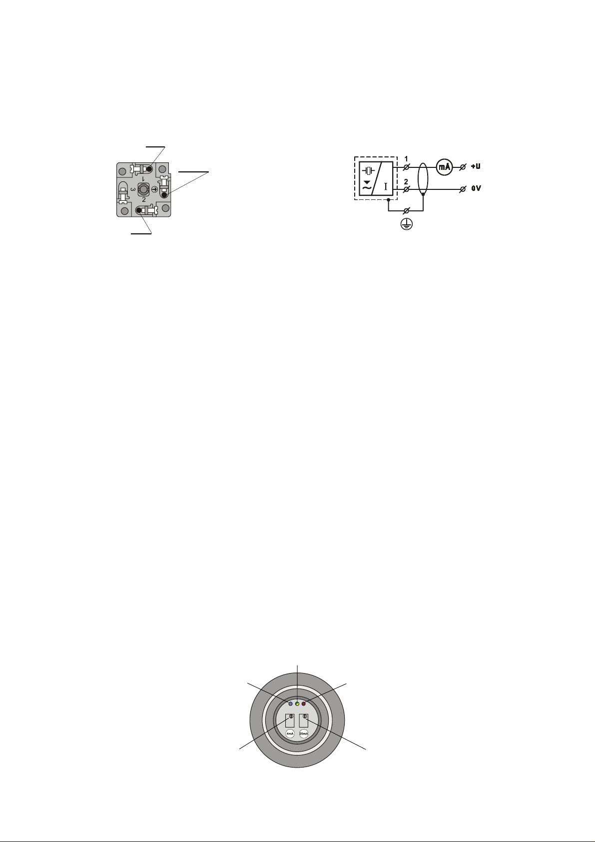
to terminal 1 and the negative pole (0 V) to terminal 2 – see fi gure 2 and 3. While making the connections the cable
must not be energised!
The level meter is connected to an evaluating device using a suitable two-core cable with an external diameter of
6-8 mm (recommended cross section of cores: 0,5 – 0,75 mm2). A shielded cable must only be used if the lead is
longer than 30 m or in the case of parallel lead togheter with power lines.
For supplying we advice a stabilized supply unit of safe voltage 12-30 VDC (SELV type), which can be part of the
connected evaluating device (for the ULM-55N type) or through an intrinsically-safe isolating repeater with supply
voltage 12-30 VDC, e.g. IRU-420 (for the ULM-55Xi type).
+U
shielding
0V
Figure 2: The inside of the GDM connector
Figure 3: Connection scheme
IV. Putting the unit into operation
The ULM-55N type: switch on the power supply (12-30 VDC).
The ULM-55Xi type: switch on the intrinsically safe isoating repeater (IRU-420).
V. Setting up
The level meter is set up by following steps. Use the adjusting elements located under the cap nut to set the
unit up – see fi gure 4.
Procedure:
1. Level meter is connected to the supply line via a miliampere meter (controller, etc.).
2. Disconnect the connector for access to adjusting elements and unscrew the cap nut (mind the internal wires).
Connect again the connector.
3. Empty the tank to the minimum level or put the level meter to the corresponding distance. Set the static current
by "4 mA" trimer to 4 mA.*
Turning to the right (clockwise) increases the current, while turning to the left decreases the current.
4. Fulfi ll the tank to the maximum level or put the level meter to the corresponding distance. Set the static current
by "20 mA" trimer to 20 mA.*
When it is impossible to fulfi ll the maximum level, then can be used any known (detectable) level and then set
appropriate current by next calculation:
I out = 4 + (0,16 x the level height in %) [mA]
5. To achieve maximum accuracy, it is advisable to re-check the setting of both limit values.
*
The trimmers do not have stop pieces – they can be turned approximately 15 times.
green-yellow wire
(shielding)
blue wire
(-)
trimer 4 mA
(minimum level
setting)
Figure 4: Adjusting elements
(top view of the internal electronic part)
ULM-nav-2.4
brown wire
(+)
trimmer 20 mA
(maximum level
setting)

Setting the level meter up inside the measured vessel (cesspit) is also possible and we recommend it especially:
- if accurate data of individual distances are not available
- if it is necessary to measure hot media (the meter must be tempered for about 1 hour before adjusting it;
the meter is equipped with temperature compensation)
- if it is necessary to measure a rippled surface (e.g. due to a nearby infl ow)
Note:
1) Set up the level meter is possible to proceed by simpler way outside of the measured tank. For example opposite a wall or opposite a fl at surface (sized aprox. 1 x 1m). Level meter must be perpendiculary targeted to
the measured surface (wall). While moving the level meter please avoid jumping distance changes (control
logic in ULM presuppose smooth level movement, jumping distance can be incorrectly evaluated).
2) If you don´t succeed in the level meter´s setting, or you don´t know at which distance the level meter is sett
then fi rst set the level meter to the basic stage by turning the trimer "20 mA" fully to the left (approximately 15
turn anti-clockwise).
3) If the level (refl ected surface) comes to the dead zone (see the catalogue’s data) during the setting, then the
current increases to the alarm value >21mA.
This value is kept, untill the level meter doesn´t register the continuous motion of the level away from the dead
zone to the nominal measuring range (jumping distance is evaluated as a permanent fault).
If the alarm signaling continues and it is impossible to put the current back by any motion of the level, then it
is necessary to make “Reset” of the level meter (disconnection and connection of the power supply).
The level meter makes level detection again.
4) Depending on the type, the level meter is set up by default for the following ranges:
ULM-55_-02 - 0,5 m (20 mA) to 2 m (4 mA)
ULM-55_-06 - 1 m (20 mA) to 4 m (4 mA)
ULM-55_-10 - 1 m (20 mA) to 8 m (4 mA)
VI. Usage, operation and maintenance
The level meter requires no operating personnel. In the case of operation, the optional local connected display
informs operating personnel about the measured level.
The maintenance of the unit includes a check-up on the good condition of the level meter and the supply cable.
Depending on the nature of the measured substance, we recommend to inspect the cleanliness of the emitting
surface at least once per year, and clean it if necessary, if detecting any visible damage. Contact the producer or
dealer immediately.
It is forbidden to modify or tamper in any way the ULM-55 unit without the approval of the producer. Repairs may
only be carried out by the producer or a service organisation authorised by the producer.
The ULM-55 unit must be assembled, installed, put into operation, operated and maintained in accordance
with these instructions, and the provisions of valid standards concerning electrical equipment installation must
complied with the ULM-55 features.
VII. Protection, safety, compatibility and non-explosiveness
The level meter is equipped with a protection against a reversal of polarity of supply voltage and against current
overload. Safety low voltage according to the Czech State Norm CSN 33 2000-4-41 protects against dangerous
touch. Electromagnetic compatibility is ensured in accordance with the Norms EN 55022/B, EN 61326-1, EN 610004-2, EN 61000-4-3, EN 61000-4-4, EN 61000-4-5, EN 61000-4-6. The non-explosiveness of the ULM-55Xi type is
certifi ed by FTZÚ-AO210 Ostrava-Radvanice, certifi cate number FTZÚ 02 ATEX 0263.
VIII. Labelling
The cap nut of the ULM-55N type contains the following information:
- Producer’s/ label and contact information
- Type of the level meter ULM-55N-_ _ (old version) or ULM-55N-_ _A (new version)
- Year of production (fi rst two digits) and serial number (remaining three digits) xx-xxx
- Supply voltage: U = 12÷30 VDC
- Range of output current I = 4÷20 mA
- Range of head working temperatures ta = - 30 … +70 °C (or ta= - 30 ... +60 °C for ULM-55N-10)
- Protection: IP65 / IP67
- CE labelling
- mark of electronic device waste (bin)
ULM-nav-3.4

ULM nav 4
.4
The cap nut of the ULM-55Xi type contains the following information:
- Producer’s label and contact information
- Type of the level meter ULM-55Xi-_ _ (old version) or ULM-55Xi-_ _A (new version)
- Year of production (fi rst two digits) and serial number (remaining three digits) xx-xxx
- Ex labelling in the hexagon
- rgerhgType II1/2GExiaIIBT5
- Number of the spark safety certifi cate
- Limit operating parameters U
= 30 VDC, Ii = 132 mA, Pi = 0,99 W, Ci = 370 nF, Li = 0,9 mH
i
- Range of head working temperatures ta = - 30 … +70 °C, ta = - 20 … +60 °C zone 0
- Protection: IP65 / IP67
- CE labelling
- Number of the authorised person inspecting the quality system
- mark of electronic device waste (bin)
IX. Standard accessories
For each sensor - 1 connecting GDM connector
For each delivery (per each 5 pieces)
- 1 adjusting screwdriver
For more detailed information about the product see www.dinel.cz
Dinel, s.r.o., U Tescomy 249, CZ - 760 01 Zlin - Priluky, Tel.: +420-577 002 003, fax: +420-577 002 007
E-mail: sale@dinel.cz Web: http://www.dinel.cz
05. 2007
 Loading...