

Dinel ULM–53 Instruction Manual
Read carefully the instructions published in this manual before the fi rst use of the level meters. Keep the manual
at a safe place. The manufacturer reserves the right to implement changes without prior notice.
INSTRUCTION MANUAL
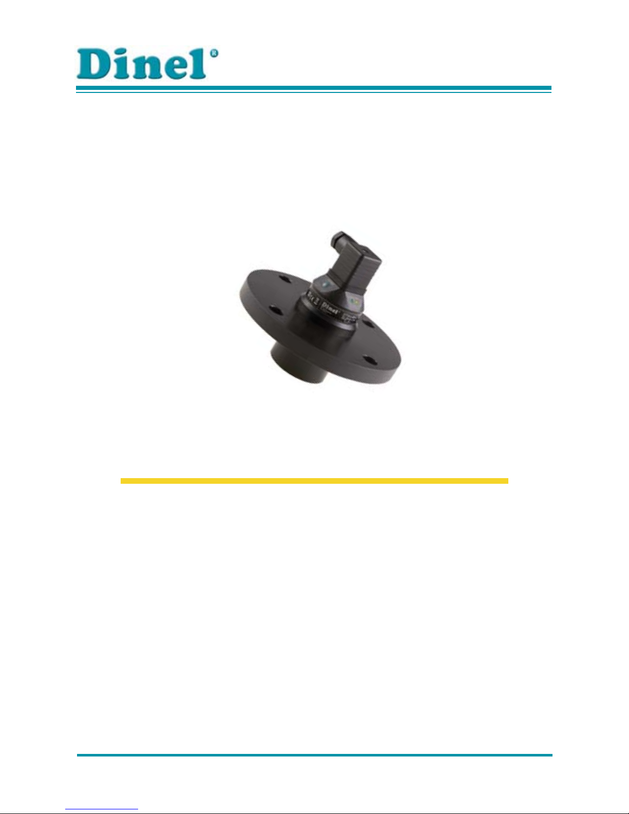
ULTRASONIC LEVEL METERS ULM–53


CONTENT
Safety ...............................................................................................................................................3
Measuring principle ..........................................................................................................................3
Range of application ........................................................................................................................3
Features of variants .........................................................................................................................3
Dimensional drawings ....................................................................................................................4
Installation instructions ....................................................................................................................5
Electrical connection ......................................................................................................................8
Set-up elements ...............................................................................................................................8
Status and failure signalization ........................................................................................................9
Operational modes ..........................................................................................................................9
Setting up .........................................................................................................................................9
Order code ..................................................................................................................................... 11
Accessories ....................................................................................................................................11
Safety, protection, compatibility and explosion proof ....................................................................11
Use, manipulation and maintenance .............................................................................................11
Marking of labels ............................................................................................................................12
Technical specifi cations .................................................................................................................16
Area classifi cation ..........................................................................................................................17

ULM–53 © Dinel, s.r.o.
3
SAFETY
All operations described in this instruction manual have to be carried out by trained personnel or by
an accredited person only. Installation, commissioning, operation and maintenance of the ultrasonic
level meters has to be carried out in accordance with this instruction manual; the provisions of
regulations in force regarding the installation of electrical equipment have to be adhered to.
Improper use, installation or set-up of the sensor can lead to crashes in the application, (over fi lling
of the tank or damage of system components).
The manufacturer is not responsible for improper use, loss of work caused by either direct or
indirect damage, and for expenses incurred at the time of installation or during the period of use
of the sensor.
Customer service must be carried out by the manufacturer exclusively.
MEASURING PRINCIPLE
The ULM® ultrasonic level meters are compact measurement devices containing an ultrasonic
transmitter and an electronic module. Using an transmitter, level meters transmit the series of
ultrasonic pulses that spread towards the level surface. The transmitter recuperates refl ected
acoustic waves that are subsequently processed in the electronic module. Based on the period
during which the individual pulses spread towards the level and back, this period is averaged by
the electronics that performs temperature compensation and subsequently a conversion to an
output current (voltage).
RANGE OF APPLICATION
For continuous non-contact level measurement of liquids (water solutions, sewerage water, etc.),
mash and paste materials (sediments, sticks, resins etc.) in closed or open vessels, sumps, reservoirs and open channels. In case the level of bulk-solid materials is measured, the measurement
range is reduced.
All setting-up is done using two buttons positioned in the upper part of the sensor. The level meter
is equipped with optical state indication (STATE) and with a setting-up process (MENU). The level
meter can output current or voltage signals. They are manufactured in model versions for nonexplosive areas (N) and explosive areas (Xi).
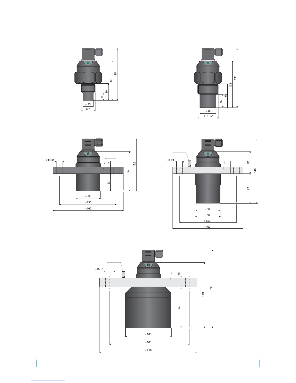
ULM–53_–02–_ measuring range from 0.25 m to 2 m, plastic PVDF transmitter and plastic
body (PP+HDPE), process connection with thread G 1".
ULM–53_–06–_ measuring range from 0.25 m to 6 m, plastic PVDF transmitter and plastic
body (PP+HDPE), process connection with thread G 1 ½".
ULM –53_–10–_ measuring range from 0.5 m to 10 m, plastic PVDF transmitter and plastic
body (PP+HDPE), aluminium alloy ("Xi" version) or HDPE ("N" version)
fl ange.
ULM –53_–20–_ measuring range from 0.5 m to 20 m, with plastic PVDF transmitter and
plastic body (PP+HDPE), aluminium alloy fl ange.
FEATURES OF VAR I ANTS
4
© Dinel, s.r.o. ULM–53
DIMENSIONAL DRAWINGS
ground
terminal
ULM–53_–02–_
ULM–53_–06–_
ULM–53N–10–_
ULM–53_–20
–_
ULM–53Xi–10–I
Al alloy
ground
terminal
Al alloy
HDPE
ULM–53 © Dinel, s.r.o.
5
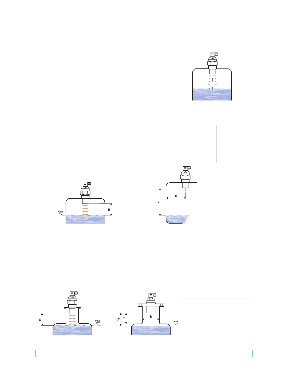
Fig. 2: Level meter dead zone
m – Dead zone
INSTALLATION INSTRUCTIONS
Install the level meter in a • ver tical po s ition into the upper lid of the tank (vessel) or reservoir
using a lug, a fastening nut or a fl ange in such a way that the ULM axis is perpendicular to the
level of the measured liquid (Fig. 1).
M i n i m u m • dimension parameters when installing into
a lid or a ceiling of a tank are listed in Fig. 3.
When installing in an • open channel (reservoir, drain
and the like), install the level meter onto a console to
the expected maximum level as close as possible.
In compliance with the measurement principle, no sig-•
nals refl ected in the area directly below the level me-
ter (the so-called dead zone) can be evaluated. The
dead zone (Fig. 2) determines the minimum distance
possible between the level meter and the highest surface level. Medium minimum distance parameters are
listed in chapter on "Technical specifi cations".
It is necessary to install the level meter in such a way •
that the bin level does not interfere with the dead
zone when fi lled up to the maximum. If measured level
interferes with the dead zone, the level meter will not
work properly.
Fig. 1: Recommended installation
in the tank
Fig. 4: Possible installation of the installation neck
Fig. 3: Installation distance from the tank wall
d – Distance from tank
wall
c – Measuring range
In case the maximum surface level in the tank interferes with the dead zone, the level meter •
has to be mounted into a higher installation neck. Subsequently, the tank can be fi lled nearly
up to the maximum volume. The neck's inner surface has to be even and smooth (without
edges and welded joints), the inner edge should be rounded in the position point where the
ultrasonic waves leave the pipe. Choose the largest possible neck's diameter, but keep the
neck's height as low as possible. Recommended dimensions of the neck are listed in Fig. 4.
a – Neck height
b – Neck width
m – Dead zone
ULM–53–02 ; 06
a < 3 b
b > 100 mm
ULM–53–10
a < 1,5 b
b > 100 mm
ULM–53–20
a < 1,5 b
b > 150 mm
ULM–53–02 ; 10
d > 1/12 c
(min. 200 mm)
ULM–53–06
d > 1/8 c
(min. 200 mm)
ULM–53–20
d > 1/10 c
(min. 200 mm)
 Loading...