

Dinasaw Dino Instruction Manual
''DINO''
BANDSAW
PROFILER
Automatic
INSTRUCTION
MANUAL
Dinasaw
Pty.
Ltd.
13
Industrial
Ave.
Caloundra.
Queensland.
4551
Australia
Phone:
$1,
7 54914999
Fax:
$1.l7
549
L7809
Email:
dinasaw@ozemail.com.au
LIMITED
WARRANTY:
Dinasaw
Pty
Ltd
warrants
that
its
products
will
b
failure
to
conform
to
this
waffanty
appear
within
Ltd
shall
upon
notification
of and
substantiation
maintained
in
accordance
with
Dinasaw's
specifi
sole
option,
uny
.o*ponents
or
parts of
the
product
determined
by
Dinasaw
to
be
defective'
This
warranty
is exclusive
and
is
in
lieu
of
any
warranty
of
merchantability,
fitness
for
a
particular
putpose
or
other
warranty
of
quality,
whether
express
or
implied'
LIMITATION
OF
LIABILITY:
Dinasaw
shall
not
under
any
circumstances
be
liable
fo
limited
to,
Y
purchased
P
forth herei
o
connection
therewith
such
as
the
performance
or
breac
or
use
of
any
goods
covered
by
or furnished
by
Dina
strict
tort,
or
under
any
waffanty,
or otherwise,
shall
of
the
goods upon
which
such
liability
is
based'
The
warranty
period
for
Dinasaw
Pty
Ltd
products
is
six
months
from
date
of
purchase'
Blades'
chains'
sprockets
and
grinding
wheels
are
excruded
from
the
warranty.
Parts
damaged
through
abuse
are
excluded
from
the
warranty.
No
transportation
costs
of
any
kind
are
covered
under
this
warranty.
Transportation
charges
to
return
products
for repair
shall
be
the
responsibility
of
the customer.
Returned
gota,
shalibe
at
the
customefs
risk
and
expense.
Dinasaw
Pty
Ltd .
Automatic
Prof
iler
DESCRIPTION:
I
PF
12v
grinderis
avers
m
19
3'5")
in
width
with
tooth
the
"Dino"
Automatic
Se
el
around
the
band
wheels'
acks,
esPeciallY
in
the
the
cutting
edge
keen,
but
serious
Problems'
mamountofmaterialoverthewholetoothprofile,
Premature
:
t[::,
shape
Read
these
instructions
thoroughly
before
using
the
grinder.
Make
all
major
adjustments
with
the
motor
switched
off.
when
initia[y
setting
up,
,..rrouI
the
Iuse
from
the
grinder
motor
to
prevent
unintentional
starting.
ALWAYS
WEAR
SAFETY
VISOR
AND
DUST
MASK
WHEN
USING
THIS
GRINDER!
Included
with
the
machine
are
the
following
tools
and
accessories:
*lx
3mm
Hexagonal
KeY
(Allen
KeY)
xlx
4mm
Hexagonal
KeY
(Allen KeY)
*lx
5mm
Hexagonal
KeY
(Allen KeY)
*lx
10-13mm
sPanner
1x
Tube
Spanner
dog
end
(optional
Bevel
Hd)
*1x
125mm/
Grinding
Wheel
'
*lx
Grinding
Wheel
Dressing
Stick
*1x
AC
Power
Cable
(no
Plug)
*lx
DC
Power
Cable
including
cliPs
x1x
Blade
SupPort
Frame
*3x3
telescoping
Arms
+ Blade
support
posts
*lx
Manual
Place
the
"'W"
section
of
the
blade
support
frame
on
a
fl
machine
and
set
it
on
the
frame
with
the
front
side
facin
through
the
ers
(103)
to
us
Unwrap
the
this
Point
it
s(
lgmm
(3/4"
rinding
whe
will
not touch
the
blade'
Once
you
have
done
that,
install
the
grind
stone
(note left
hand
ing
wheel
s
more
chamfered
edge
facing
down.
Inr"rt
the
teiescopic
blade
to
the
"W'
vertical
blade
,oppo.t
rods
and
in their
extreme
ends
and
tighte
with
the
6
Fit
the
plastic
strieta
(115)
to the
cover
(99)
using
2 M5x10
pan
head
screws
suppiied'
Dinasaw
Pty
Ltd
.
Automatic
Profiler
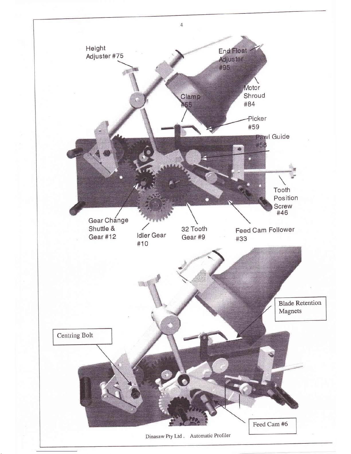
Height
Adjuster
#
Gear
Change
Shuttle
&
Gear
#12
ldler
Gear
#10
32
Tooth
Gear
#9
'i,:
,,!i.r,i
\ .,!.r:1'.:1
b..*.1,t;
Feed
Cam
Follower
#33
Tooth
Position
Screw
#46
Blade
Retention
Magnets
Feed
Cam
#6
Shroud
#84
icker
#59
Dinasaw
Pty
Ltd
. Automatic
Profrler
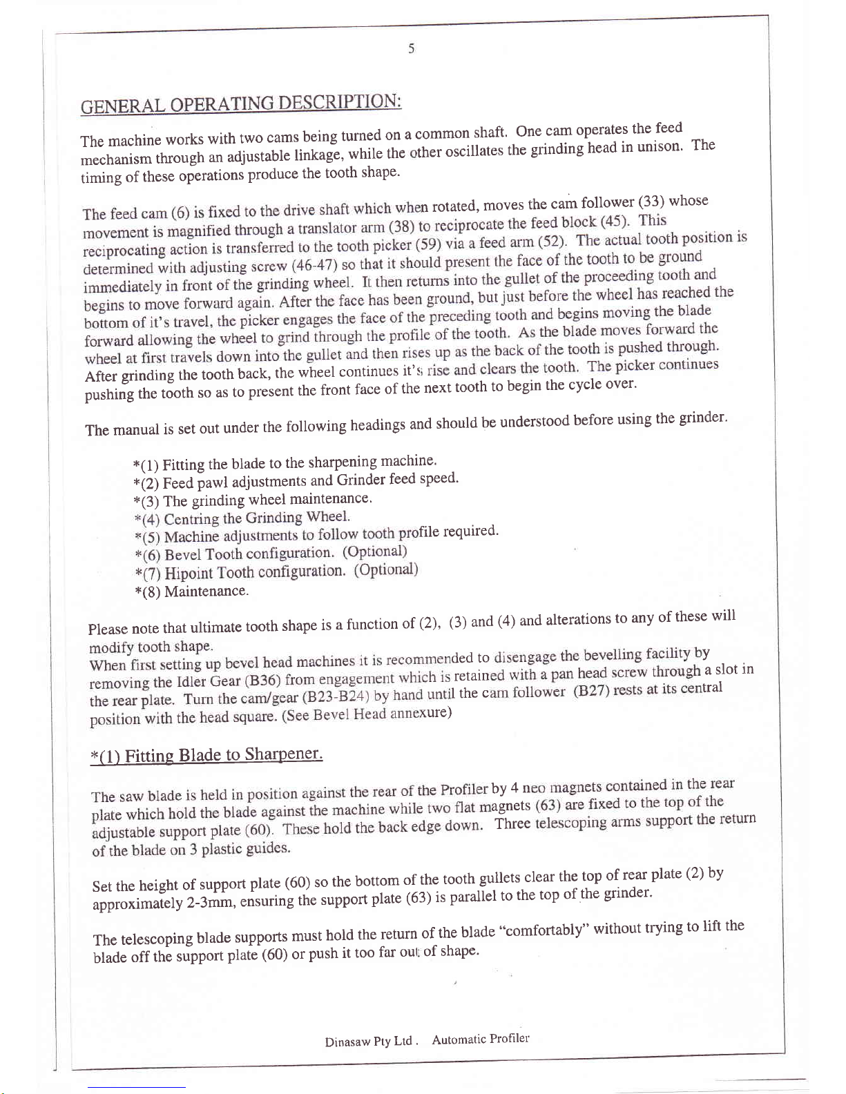
The
machine
works
with
two
cams
being
turned
on
a
common
shaft'
one
cam
operates
the
feed
-,
mechanism
through
an
adjustabre
rinkag"e,
while
the
rther oscillates
the
grinding
head
in
unison'
The
timing
of
these
operations
produce
the
tooth
shape'
n
rotated,
moves
the
cam
follower
(33) whose
After
grinding
the
tooth
back,
the
wheel
continues
it's
pushirig
the
tJoth
so
as
to
present
the
front
face
of the
next
tooth
to
begin
the
cycle
over'
The
manual
is
set
out
under
the
following
headings
and
should
be
understood
before
using
the
grinder'
t(1)
Fining
the
blade
to
the
sharpening
mach-ine'
*iZ)
feed
pawl
adjustments
and
Grinder
feed
speed'
*(3)
The
grinding
wheel
maintenance'
file
required'
*(8)
Maintenance.
please
note
that
ultimate
tooth
shape
is
a function
of
(2),
(3)
and
(4)
and
alterations
to
any
of
these
will
ded
to
Y
retain
a
slot
in
I the
c
tral
xure)
*(1)
Fitting
Blade
to
SharPener'
bY4n
agnets
Three
rn
Set
the
height
of
support
plate
(60)
so
rhe
bortom
of
the
toorh
gullets
clear
the
top
of
rear
plate
(Z)by
approximately
2-fmm,
ensuring
the
support
plate
(63)
is
parallel
to
the
top
of
the
grinder'
The
telescoping
blade
supports
must
hold
the
return
of
the
blade
"comfortably"
without
trying
to
lift
the
blade
off
thi
sopport
ptate
1OO;
or
push it
too
far
oul
of
shape'
Dinasaw
Pty
Ltd
'
Automatic
Profiler

6
The
blade
must
be
allowed
to
travel.around
easily.
Rusted,
gummed
or
kinked
blades
will
not
travel
smoothlyandwillhavetobecleanedorrepairedbeforesharpening.
The
magnetic
sensor
switch
(65) sits
on
top
of
the
support
plate'
Placing
the
8
x
3mm
magnet
on
the
inside
face
of
the
brade
will
stop
the
machine
when
the
magnet
presents
next
to
the
sensor'
This
switch
is
fragile
so
use
care
when
fitting
or
removing
blades'
to
the
Feed
Pawl
Arm
(52)'
The
teeth
are
indexed
bY
means
of
an
of
movement
(oscillation)
imparted
by
slot
of
the
Translator
Arm
(38)'
movement
(osculation)
while
moving
it
right
(away
from
cam)
increases
this
movement'
The
bearin
E
G4)
is
secured
to
the
Translator
arm
Translator
Arm
with
a
5mm
screw
thread
(64) ac
face
and
the
gullet)'
The
speed
of
the
feed
is
selected
using
the
switch
"H
This
the
rotation
of the
feed
motor,
which
in
turn
shuttles
the
drive
gear
(11)
high
A
further
speed
option
is
available
by
shifting
the
wire
terminals
on
tl
r'
M
re
along
to
the
top
motor
terminal
increases
feed
motor
speed'
It is
factory
set
to the
lower
speed'
The
appropriate
th
Pitch
al
being
removed.
Large
ng
requ
finer
pitches
and
light
cuts
can
be
or
adju
use
low
speed'
(3\
The
Grindine
Wheel.
When
new,
the
Grinding
wheel
has
a square
edge
around
the
rim,
which
must
be
dressed
to
a
shape'
which
will
conform
to
the
rooth
shape.
This
is
done
with
the
dressing
stick
supplied
by
holding
it against
the
rotating
wheel.
Dinasaw
Pty Ltd
.
Automatic
Profiler
7
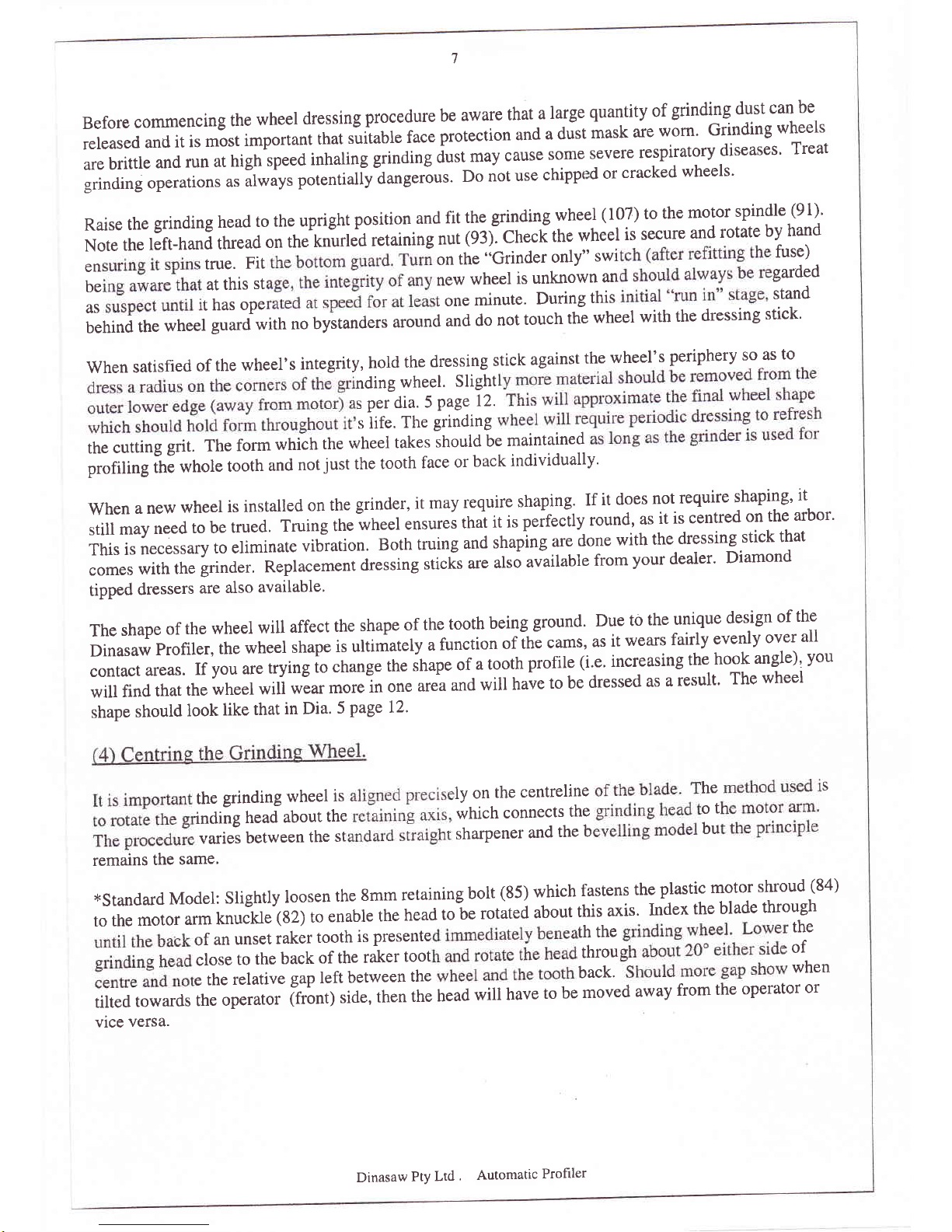
Before
commencing
the
wheel
dressing
procedure
be
aware
that
a
large
quantity
of
grinding
dust
can
be
released
and
it
is
most
important
that
suiiable
face
protection
and
a
drist
mask
are
worn'
Grinding
wheels
are
brittle
and
run
at
high
speed
inhaling
grinding
dust
may
cause
some
severe
respiratory
diseases'
Treat
grinding
operations
u.
If*uy,
potentialiy-a*g.tiot.
Do
not
use
chippt
d
or
cracked
wheels'
Raise
the
grinding
head
to
the
upright
position
and
fit
the
gnnding
wheel
(107) to
the
motor
spindle
(91)'
Note
the
left-hand
thread
on
the
knurled
retaining
nut
(93).
checfthe
wheel
is
secure
and
rotate
by
hand
en
true.
Fit
on
the
"Grinder only"
swi
fuse)
beatthisstnewwheelisunknownangarded
as
t
has
ope
t
one
minute'
During
this
stand
behind
the
wheel
guard with
no
bystanders
around
and
do
not
touch
the
wheel
with
the
dressing
stick'
when
satisfied
of
the
wheel,s
integrity,
hold
the
dressing
stick
against
the
wheel's
periphery
so
as
to
l"'J,,J.lTi.ll'tl:
s life.
The
grinding
the
cutting
grit.
The
form
which
the
wheel
takes
should
be
maintained
profiling
ihE
whole
tooth
and
not
just
the
tooth
face
or
back
individually'
when
a new
wheel
is
installed
on
the
grinder,
it may
require
shaping'
If
it
does
not
require
shaping'
it
still
may
need
to be
trued.
Truing
the
wheel
.nrur.,
that
it is
peirecily
round,
as
it
is
centred
on
the
arbor'
This
is
necessary
to eliminate
vibration.
Both
truing
and
shaping
are
done
with
the
dressing
stick
that
comes
with
the
grinder,
Replacement
dressing
sticis
are
also
uuuilubl"
from
your
dealer'
Diamond
tipped
dressers
are
also
available'
The
shape
of
the
wheel
will
affect
the
shape
of
the
tooth
being
ground.
Due
to
the
unique
design
of
the
Dinasaw
profiler,
the
wheel
shape
is ultimately
a
function
of
It
"
carns,
as
it
wears
faiily
evenly
over
all
contact
areas.
If
you are
trying
to
change
the
shape
of
a tooth
profile
(i.e' increasing
the
hook
angle),
You
will
find
that
the
wheel
will
wear
rnor.ln
on.
ur*
and
will
have
to be
dressed
as
a result'
The
wheel
shape
should
look
like
that
in Dia.
5
page 12'
thegrindingwheelislyonthecentrelineheS
inding
heaiabout
the
which
connects
the
o t
varies
between
the
st
sharpener
and
the
b
bu
remains
the
same.
*Standard
Model:
Slightly
loosen
the
gmm
retaining
bolt
(85) which
fastens
the
plastic
motor
shroud
(84)
to
the
motor
arm
knuckle
(g2)
to
enabie
the
head
to
be
rotatei
about
this
axis.
Index
the
blade
through
of
an
unset
raker
tooth
is
presente
th
the
the
close
to
the
back
of the
raker
toot
throu
of
e
the
relative
gap left
between
the
back'
when
tilted
towards
the
operator
(front)
side,
then
the
head
will
have
to
be
moved
away
from
the
operator
or
vice
versa.
Dinasaw
Pty
Ltd
.
Automatic
Profiler
8
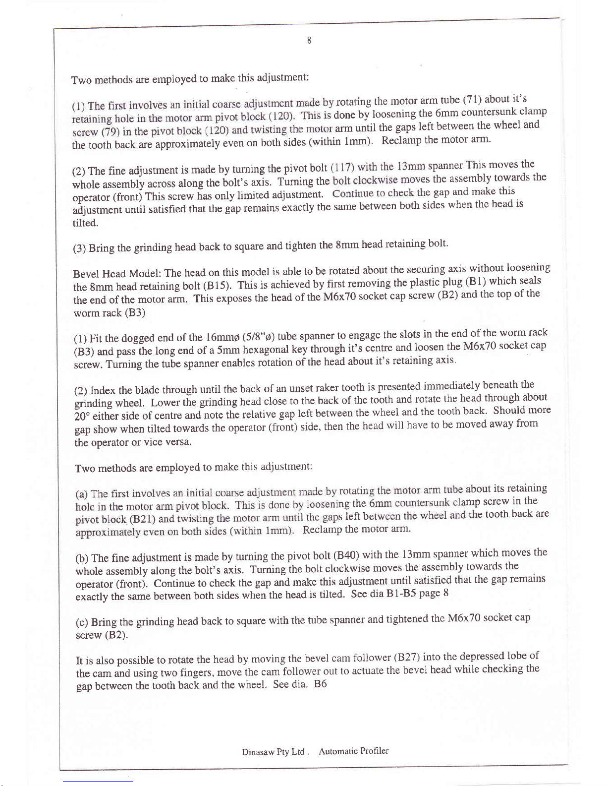
Two
methods
are
employed
to
make
this
adjustment:
J;lTif
,'*}:l"J,xnHHJllmi:Jli':1"",n
arm
until
the
gaps
left
between
the
wheel
and
the
tooth
back
are
approximately
even
on
both
sides
(within 1mm)'
Reclamp
the
motor
arm'
(2)
The
fine
adjustment
is
made
by
turning
the
pivot
bolt
spanner
This
moves
the
whole
assembly
across
along
the
bolt's
ax]s.
furning
the
s the
assembly
towards
the
operator
(frontj
This
screw
f,as
only
limited
adjustment.
e
gap
and
make
this
adjustment
until
satisfied
that
the
gap
remains
Lxactly
the
same
between
both
sides
when
the
head
is
tilted.
(3)
Bring
the
grinding
head
back
to square
and
tighten
the
8mm
head
retaining
bolt'
Bevel
Head
Model:
The head
on
this
model
is
able
to
be
rotated
about
the
securing
axis
yithoyt
tgosening
the
gmm
head
retaining
bolt
(B
15).
This
is
achieved
by
first
removing
the
plastic
plug
(B
1)
which
seals
the
end
of
the
moror
ur*.
tt
i, exposes
the
head
of
the
M6x70
socket
cap
screw
(B2)
and
the
top
of
the
worm
rack
(83)
(1)
Fit
the
dogged
end
of
the
16mmp
618-r4
tube
spanner
to
engage
the
slots
in
the
end
of
the
worm
rack
(B3)
and
pass
the
long
end of a
5mm
hexagonal
t<ey
ttrough
it's
centre
and
loosen
the
M6x70
socket
cap
,.*.
Tgrning
the tu6e
spanner
enables
rolation
of
the
head
about
it's
retaining
axis'
(2)
Index
the
blade
through
until
the
back
of an
unset
raker
tooth
is
presented
immediately
beneath
the
grinding
wheel.
Lower
the
grinding head
close
to the
back
of the
tooth
and
rotate
the
head
through
about
20"
either
side
of centre
and
note
the
relative
gap
left
between
the
wheel
and
the
tooth
back'
Should
more
gap
show
when
tilted
towards
the
operator
(fr6ni)
side,
then
the
head
will
have
to
be
moved
away
from
the
operator
or vice
versa'
Two
methods
are
employed
to
make
this
adjustment:
rotatin
about
its
retaining
ng the
mP
screw
in
the
s
left
b
the
tooth
back
are
eclamP
the
motor
arm.
(b)
The
fine
adjustment
is made
by rurning
the
pivot bolt
(B40)
with
the
13mm
spanner
which
moves
the
whole
assembly
along
the
bolt's
uiir.
tuiringltre
bolt
clockwise
moves
the
assembly
towards
the
operator
(frontj.
Coniinue
to check
the
gap
and
make
this
adjustment
until
satisfied
that
the
gap
remains
exactly
the
same between
both
sides
when the
head is
tilted.
See
dia
B
1-85
page
8
(c)
Bring
the
grinding
head
back
to square
with
the
tube
spanner
and
tightened
the
M6x70
socket
cap
suew
(B2).
It is
also
possible
to rotate
the
head
by
moving
the bevel
cam
follower
(827)
into
the
depressed
lobe
of
the
cam
and
using
two
fingers,
move
the
cam
follower
out
to
actuate
the
bevel
head
while
checking
the
gap
between
the tooth
back
and
the
wheel.
See
dia.
86
Dinasaw
Pty Ltd
. Automatic
Profrler
 Loading...