

Dinan Tronics D440-0052 Installation Instructions Manual

INSTALLATION INSTRUCTIONS
PART NUMBER D440-0052
APPLICATIONS:
12/14-2017 F55 Mini Cooper S (5-door with 2.0L B46/B48 engine)
12/14-2017 F56 Mini Cooper S (3-door with 2.0L B46/B48 engine)
________________________________________________________________
PARTS LIST
Qty Part # Description
1 D443-0041 DINANTronics Elite ECU
1 D442-0036 Harness; B48 Elite, Late
1 D443-0042 Bypass Plug
10 D502141 Zip ties
4 DT441-0022 HD Velcro Strips
________________________________________________________________
Congratulations for being selective enough to use DINANTronics Elite Performance
Tuner. We have spent many hours developing this kit to assure that you will receive
maximum performance and durability with minimum difficulty in installation. Please take
the time to read these instructions and call us if you have any difficulties during the
installation.
NOTE: This kit does not fit all combinations of vehicles & engines. Please pay careful
attention to the vehicles listed above. Note -- this kit is NOT suitable for JCW vehicles.
Do not install this kit if your specific vehicle configuration is not shown. Please contact
your Dinan representative if you have any questions.
PREPARE VEHICLE FOR INSTALLATION:
a) Park vehicle at the location where you will be installing DINANTronics.
b) Determine the range of the keys.
Step away from the vehicle and attempt to lock or unlock the car using the
remote.
Continue to move away until the car no longer responds to the key. This is the
range of the key.
INS440-0052 Page 1 of 7 Rev 9/18/17
During DINANTronics installation, ALL keys must be completely outside this
DINANTronics
ECU may be
mounted here
#1
#2
#3
range. If a key remains within range of the car, the vehicle may respond to the
key and awaken unexpectedly, which could result in a stored fault and check
engine light.
c) Unlock the car and open both the hood and trunk.
d) Close all the doors.
e) Move all keys beyond the range of the car.
f) Leave the vehicle undisturbed for about 10 minutes. This allows adequate time for
the electronics to go to sleep.
g) Disconnect negative terminal of battery.
DINANTronics INSTALLATION:
1. Remove the engine cover by tugging upwards to release the clips, then set cover
aside.
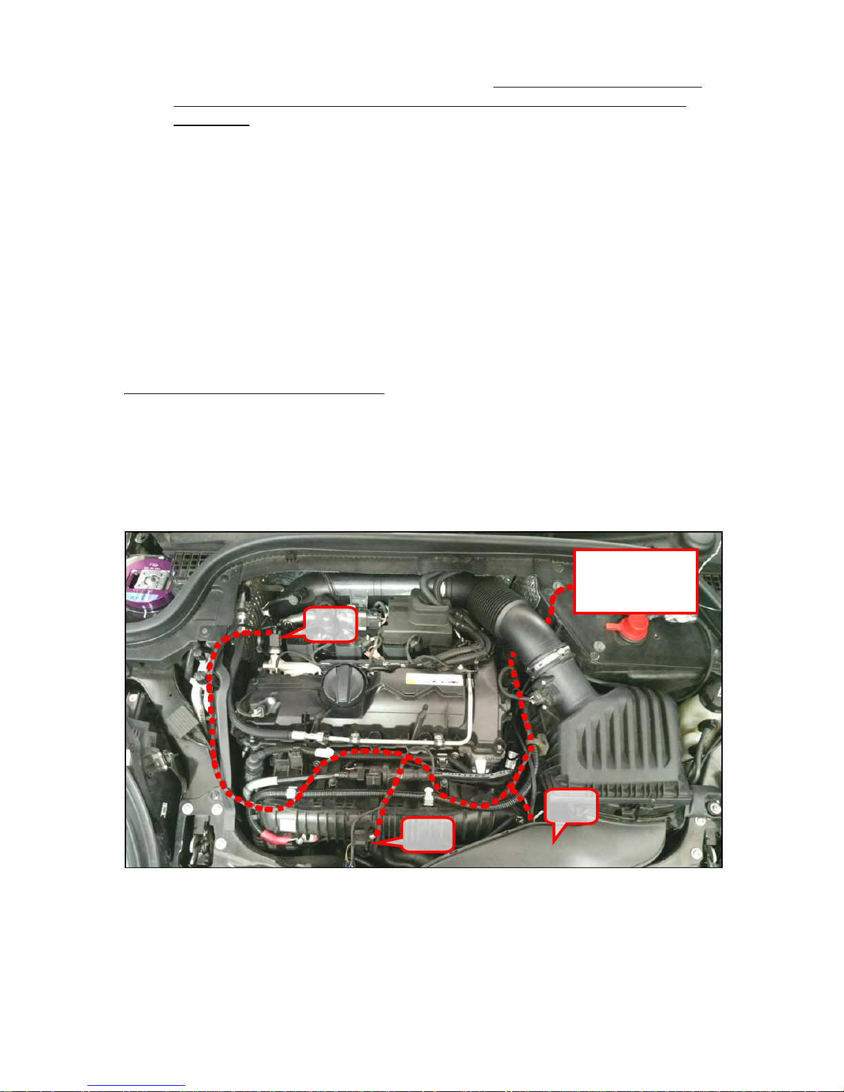
2. The DINANTronics ECU communicates with 3 pressure sensors in the engine
compartment, shown in the layout photo below.
NOTE: There are two possible connector styles for Sensor #3. You may
wish to glance at steps 11& 12, to confirm that the connector on the Dinan
harness is correct for your vehicle, before continuing with this installation.
INS440-0052 Page 2 of 7 Rev 9/18/17
3. Sensor #1 is mounted to the charge air tube, just in front of the throttle body.
#1
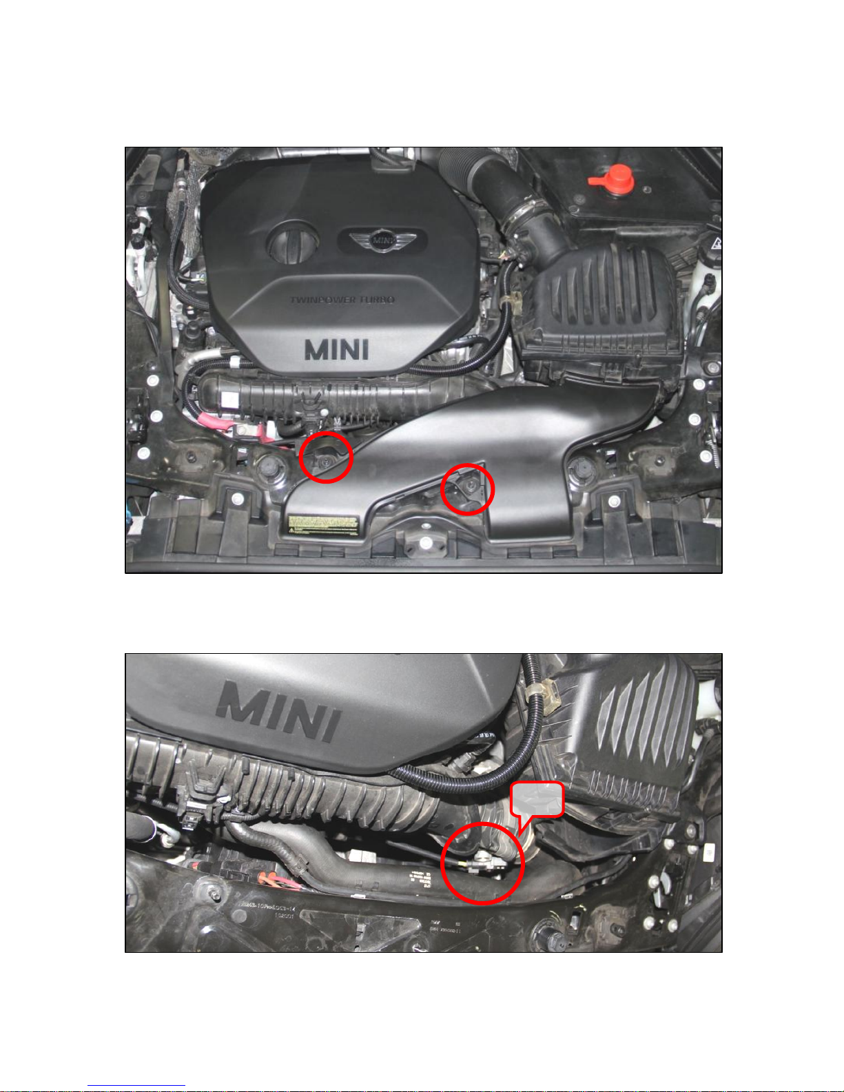
4. To access the charge air tube sensor, remove the two 10mm hex nuts and set aside
the air intake duct going to the airbox:
5. The charge air tube pressure sensor is shown below. It will have a connector that is
identical to the ones on the DINANTronics harness.
INS440-0052 Page 3 of 7 Rev 9/18/17
 Loading...