

Dinamap Pro 100V2, Pro 400V2, Pro 300V2, Pro 200V2 Operation Manual
PRO Series 100 - 400V2
Operation Manual

1
DINAMAP® PRO
Series 100-400V2
Monitor
Operation Manual
2
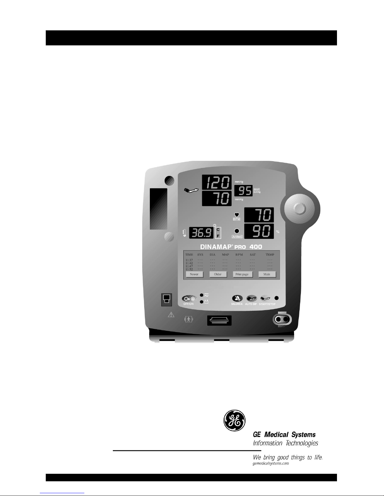
DINAMAP® PRO 400V2 Monitor

3
DINAMAP® PRO Series 100-400V2
Monitor Operation Manual
This manual is for DINAMAP® PRO Monitor Models 100V2,
200V2, 300V2, and 400V2, all with printers.
• PRO 100V2: BP and Pulse
• PRO 200V2: BP, Pulse, and Temp
• PRO 300V2: BP, Pulse, and SpO2
• PRO 400V2: BP, Pulse, Temp, and SpO2
The model of the Monitor determines which menu option
buttons appear on the LCD. Please refer to applicable
sections. The Model Number 100-400V2 is generic in nature
and reflects the range of product codes available. Your
product may be labeled with a specific product code such as
DINAMAP® PRO Model 410. "V2" refers to the second
version of the product's design.
Reissues and Updates
Changes occurring between issues are addressed through
Change Information Sheets, Addendums, and replacement
pages. If a Change Information Sheet does not accompany
this manual, it is correct as printed.
Errors and Omissions
If errors or omissions are found in this manual, please notify:
GE Medical Systems Information Technologies, Inc.
8200 West Tower Avenue
Milwaukee, WI 53223 USA
Tel: +414.355.5000
800.558.5120 (US only)
Fax: +414.355.3790
Part No. 2018548-001 A
The content of this document including all figures and
drawings is proprietary information of GE Medical Systems
Information Technologies, provided solely for purposes of
operation, maintenance or repair, and dissemination for
other purposes or copying thereof is prohibited without prior

4
written consent by GE Medical Systems Information
Technologies. Illustrations may show design models;
production units may incorporate changes.
Hierarchy of Warnings and Cautions
A general warning is a statement that alerts the user to the
possibility of injury, death, or other serious adverse reactions
associated with the misuse of the device. A warning relates
to steps in a procedure.
A general caution is a statement that alerts the user to the
possibility of a problem with the device associated with its
use or misuse. Such problems include device malfunction,
device failure, damage to the device or damage to other
property. A caution relates to steps in a procedure.
© Copyright 2003, GE Medical Systems Information
Technologies. All rights reserved.
World Headquarters
GE Medical Systems Information Technologies, Inc.
8200 West Tower Avenue
Milwaukee, WI 53223 USA
Tel: +414.355.5000
800.558.5120 (US only)
Fax: +414.355.3790
European Representative
GE Medical Systems Information Technologies GmbH
Postfach 60 02 65
D-79032 Freiburg Germany
Tel: +49 761 45 43 - 0
Fax: +49 761 45 43 - 233
Asia Headquarters
GE Medical Systems Information Technologies Asia
24th Floor, Shanghai MAXDO Center,
NO. 8 Xing Yi Road, Hong Qiao Development Zone
Shanghai 200336, P.R. China
Tel: +86-21-5208-2008
Fax: +86-21-5208-2006

5
Introduction ............................................................................ 7
About the DINAMAP® PRO Series 100-400V2 Monitor .................................9
Indications ................................................................................................................... 9
Contraindications ....................................................................................................... 9
Warnings ...................................................................................................................... 9
Cautions .....................................................................................................................10
Product Compliance ...............................................................................................12
Symbols ......................................................................................................................13
Getting Started...................................................................... 13
Unpacking the Monitor and Accessories ...........................................................15
Power Sources ..........................................................................................................15
Powering the Monitor .............................................................................................15
Rear Panel Connections .........................................................................................18
Front Panel Controls and Indicators ....................................................................19
Switching the Monitor On and Off ......................................................................21
Liquid Crystal Display (LCD) .................................................................................22
Menu Area ................................................................................................................22
Area 2 .........................................................................................................................22
Area 3 .........................................................................................................................22
Using the Printer ......................................................................................................23
Installing the Paper ..................................................................................................23
Printer Alarms ...........................................................................................................23
Storage .......................................................................................................................24
Using the Monitor ................................................................23
Noninvasive Blood Pressure Determination ......................................................25
Description ................................................................................................................25
Procedures ................................................................................................................29
Manual Mode ...........................................................................................................31
Auto Mode ................................................................................................................31
Stat Mode ..................................................................................................................32
TURBO TEMP ...........................................................................................................33
Description ................................................................................................................33
Predictive Mode .......................................................................................................34
Monitor Mode ..........................................................................................................34
Procedures for Oral Predictive Mode Determinations ....................................36
Procedures for Rectal Predictive Mode Determinations ................................37
Procedures for Monitor Mode Determinations (Axillary Determinations) .38
Masimo Set* SpO2 ..................................................................................................39
Procedures ................................................................................................................44
Patient safety .............................................................................................................44
Troubleshooting Masimo SET® SpO2 Parameter ............................................45
NELLCOR® OxiMAX™ SpO2 .............................................................................48
Description ................................................................................................................48
Procedures ................................................................................................................51
Patient safety .............................................................................................................51
Patient safety .............................................................................................................52
Troubleshooting the NELLCOR SpO2 Parameter ............................................53
Using the Menu System .......................................................55
Introduction ..............................................................................................................57
Liquid Crystal Display .............................................................................................57
Contents

6
Menu Area ................................................................................................................57
Area 2 .........................................................................................................................57
Area 3 .........................................................................................................................57
Normal Mode Menu ...............................................................................................58
Clinician Mode Menu .............................................................................................59
Rotor ...........................................................................................................................60
Menu Tree .................................................................................................................60
Main Menu ................................................................................................................60
Vitals Button (UK: All Obs) ....................................................................................61
Clear ...........................................................................................................................61
Print .............................................................................................................................62
More... Button ...........................................................................................................62
Set BP Button (UK: BP Mode) ...............................................................................62
Auto ............................................................................................................................62
Manual .......................................................................................................................63
Tgt Pressure ...............................................................................................................63
Stat ..............................................................................................................................63
Main ............................................................................................................................64
Alarms Button ...........................................................................................................64
Volume .......................................................................................................................64
Auto ............................................................................................................................65
Main ............................................................................................................................65
Trend Button .............................................................................................................65
Display ........................................................................................................................66
Newer and Older .....................................................................................................66
Print page ..................................................................................................................66
Main ............................................................................................................................66
Clear ...........................................................................................................................66
Print All .......................................................................................................................66
Main ............................................................................................................................67
Print Button ...............................................................................................................67
Auto/Man ..................................................................................................................67
Now ............................................................................................................................67
History ........................................................................................................................67
Main ............................................................................................................................67
More... Menu ............................................................................................................68
SpO2 Button (Models 300V2 and 400V2) ........................................................68
Average ......................................................................................................................68
Volume .......................................................................................................................68
Main ............................................................................................................................69
Config Button ...........................................................................................................69
Pwr Sav (Sleep Mode) ............................................................................................70
Time ............................................................................................................................71
Rotor ...........................................................................................................................71
Main ............................................................................................................................72
Temp ...........................................................................................................................72
C or F ..........................................................................................................................72
Predictive ...................................................................................................................72
Monitor ......................................................................................................................72
Display Button ..........................................................................................................73
SpO2 Pleth ................................................................................................................73

7
NIBP ............................................................................................................................73
Main ............................................................................................................................73
Service Button ..........................................................................................................73
Clinician Menu .........................................................................................................74
Error and Warning Messages ................................................................................77
Alarms Button ...........................................................................................................78
OK Button .................................................................................................................78
Appendix A............................................................................77
Technical Specifications .........................................................................................79
BP ................................................................................................................................79
US Patents .................................................................................................................79
TURBO´TEMP Temperature .................................................................................80
IVAC® Patents .........................................................................................................80
NELLCOR SpO2 .......................................................................................................80
Measurement Range ...............................................................................................80
Accuracy and Motion Tolerance ..........................................................................80
Saturation ..................................................................................................................80
Pulse Rate ..................................................................................................................81
Default Settings ....................................................................................................... 81
Measurement Range ...............................................................................................82
Accuracy and Motion Tolerance ..........................................................................82
Saturation ..................................................................................................................82
Pulse Rate ..................................................................................................................82
Masimo® Sensor Accuracy ...................................................................................83
Resolution ..................................................................................................................83
Low Perfusion Performance ..................................................................................83
Interfering Substances .............................................................................................83
Sensor Light Source .................................................................................................83
Default Settings ........................................................................................................84
Masimo Patents ........................................................................................................84
Mechanical ................................................................................................................84
Power Requirements ...............................................................................................84
Environmental ...........................................................................................................85
Appendix B ............................................................................ 85
Alarm Codes .............................................................................................................87
Patient Alarms ...........................................................................................................87
System Alarms ..........................................................................................................87
Fail-safe Alarm ...........................................................................................................87
Hierarchy of Alarms ................................................................................................88
Appendix C............................................................................91
Principles of Noninvasive Blood Pressure Determination ..............................93
Systolic Search ..........................................................................................................95
Reverting and Accelerated Determination .........................................................96
Appendix D ...........................................................................95
Reorder Codes .........................................................................................................97
Appendix E ............................................................................97
Warranty, Service, and Spare Parts ......................................................................99
Warranty ....................................................................................................................99
Assistance and Parts ................................................................................................99
Repairs ..................................................................................................................... 100
Introduction

8
Packing Instructions .............................................................................................100
Service Manuals .................................................................................................... 100
Appendix F ............................................................................99
Maintenance .......................................................................................................... 101
Cleaning the Monitor ...........................................................................................101
Cuff Cleaning and Disinfection .......................................................................... 101
General ...................................................................................................................101
Materials .................................................................................................................101
Procedure ............................................................................................................... 102
Temperature Devices ...........................................................................................102
SpO2 Sensors ........................................................................................................ 102
Storage and Battery Care ....................................................................................103
Fuses ........................................................................................................................ 104
Calibration .............................................................................................................. 104
Leak Testing ...........................................................................................................104
Disposal of Product Waste ................................................................................. 105
Appendix G .........................................................................105
Host Port Connector (rear panel) .....................................................................107

9
About the DINAMAP® PRO Series 100-400V2 Monitor
DINAMAP® PRO Monitors provide noninvasive
determination of systolic blood pressure, diastolic blood
pressure, mean arterial pressure, pulse rate, temperature, and
oxygen saturation. These portable AC- and DC-operated
monitors are primarily intended for use in hospital acute care
settings such as outpatient surgery, accident and emergency,
labor and delivery, GI/endoscopy, and medical/surgical
units.
The PRO Monitor comes in four different models: PRO
100V2, 200V2, 300V2, and 400V2, all with printers.
• PRO 100V2: BP and Pulse
• PRO 200V2: BP, Pulse, and Temp
• PRO 300V2: BP, Pulse, and SpO2
• PRO 400V2: BP, Pulse, Temp, and SpO2
All of the main operations of the PRO Monitor are easy to
use. Please review the factory default settings and, where
applicable, enter settings appropriate for your use. The
“Using the Monitor” section of this manual explains how to
use the Monitor in its most simple form, while the “Using the
Menu System” section explains how to customize
measurements by using the menu system.
Indications
The PRO Monitor is intended to monitor one patient at the
bedside.
Contraindications
This device is not designed, sold, or intended for use except
as indicated.
Federal law (U.S.A.) restricts this device to sale by or on the
order of a clinician.
Warnings
• Do not use the PRO Monitor in the presence of
magnetic resonance imaging (MRI) devices. There have

10
been reports of sensors causing patient burns when
operating in an MRI environment.
• Do not use the Monitor in the presence of flammable
anesthetics.
• To help prevent unintended current return paths with
the use of high frequency (HF) surgical equipment,
ensure that the HF surgical neutral electrode is
properly connected.
• To avoid personal injury, do not perform any servicing
unless qualified to do so.
• WARNING: These Monitors should not be used on
patients who are connected to cardiopulmonary bypass
machines.
• If powering the Monitor from an external power
adapter or converter, use only power adapters and
converters approved by GE Medical Systems
Information Technologies.
• The Monitor does not include any user-replaceable
fuses. Refer servicing to qualified service personnel.
• To reduce the risk of electric shock, do not remove the
cover or the back. Refer servicing to a qualified service
person.
• If the accuracy of any determination reading is
questionable, first check the patient’s vital signs by
alternate means and then check the PRO Monitor for
proper functioning.
Cautions
• Do not use replacement batteries other than the type
supplied with the Monitor. Replacement batteries are
available from GE Medical Systems Information
Technologies. See Appendix D.
• The PRO Monitor is designed to conform to
Electromagnetic Compatibility (EMC) standard IEC
601-1-2, 1993 and will operate accurately in
conjunction with other medical equipment which also
meets this requirement. To avoid interference problems
affecting the Monitor, do not use the Monitor in the

11
presence of equipment which does not conform to
these specifications.
• Place the PRO Monitor on a rigid, secure surface.
Monitor must only be used with mounting hardware,
poles, and stands recommended by GE Medical
Systems Information Technologies. See Appendix D.
• The weight of the accessory basket contents should not
exceed 6.6 lb (3 kg).
• Arrange the power cord, air hoses, and all cables
carefully so they do not constitute a hazard.
• Verify calibration of BP parameter (temp and pulse
oximeter do not require calibration). Ensure that the
display is functioning properly before operating the
PRO Monitor.
• Do not immerse the Monitor in water. If the Monitor is
splashed with water or becomes wet, wipe it
immediately with a dry cloth.
• Do not gas sterilize or autoclave.
• The PRO Monitor, when used with applied parts and
accessories approved by GE Medical Systems
Information Technologies, is protected against
defibrillator damage.
Notes
• Waveforms may be distorted and readings inaccurate
when electrosurgical cautery equipment is used while
monitoring with the PRO Monitor.
• The electromagnetic compatibility profile of the PRO
Monitor may change if accessories other than those
specified for use with the PRO Monitor are used.
• Trend data are retained in the PRO Monitor when it is
turned off, except when the default is overridden by
selecting the Trend button under the Service menu.

12
Product Compliance
The DINAMAP® PRO Monitor is classified in the following
categories for compliance with IEC 601-1:
• Class l, internally powered
• Transportable
• For continuous operation
• Not suitable for use in the presence of flammable
anesthetics
• Not for use in the presence of an oxygen-enriched
atmosphere (oxygen tent)
• Type BF applied parts
• IPX1, degree of protection against ingress of water
• Sterilization/Disinfection, see Appendix F
DINAMAP® PRO MONITOR
CLASSIFIED WITH RESPECT TO ELECTRIC SHOCK, FIRE
AND MECHANICAL AND OTHER SPECIFIED HAZARDS
ONLY IN ACCORDANCE WITH CAN/CSA C22.2 NO.
601.1. ALSO EVALUATED TO IEC-601-2-30.
0086
This product conforms with the essential requirements
of the Medical Device Directive. Accessories without
the CE mark are not guaranteed to meet the Essential
Requirements of the Medical Device Directive.
13
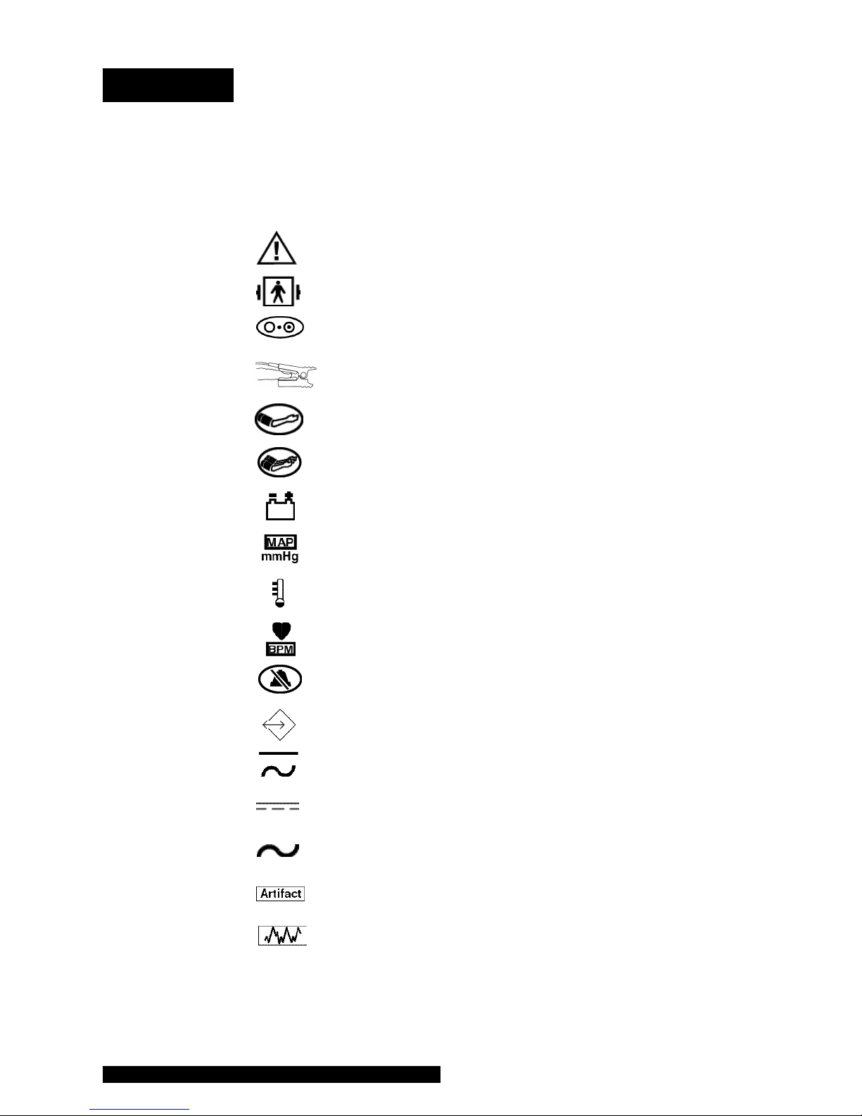
Symbols
The following symbols are associated with the PRO Monitor.
Note: The type of model determines which symbols appear
on the Monitor.
Attention, consult accompanying documents
Defibrillator-proof type BF equipment
Power ON/OFF
SpO
2
START/STOP BP
AUTO BP
Battery Power
MAP (Mean Arterial Pressure)
Temperature
Beats Per Minute
SILENCE
External Communications Port Connector
External AC or DC Power Indicator
External DC Power Input
External AC Power Input
SpO2 Motion Artifact / Low Perfusion (US)
SpO2 Motion Artifact / Low Perfusion (Europe)

14
Packaging label depicting the
transportation and storage
atmospheric pressure range
of 500 to 1060 hPa.
The DINAMAP® PRO Monitor is protected
against vertically falling drops of water and
conforms to IEC-529 standard at level of
IPX1. Vertically falling drops of water shall
have no harmful effects to the Monitor.
IPX1

15
Getting Started
Unpacking the Monitor and Accessories
Before attempting to use the PRO Monitor, take a few
minutes to become acquainted with the Monitor and its
accessories. Unpack the items carefully, and check them
against the contents checklist enclosed in one of the
accessory boxes. This is also a good time to check for any
damage or shortage. If there is a problem or shortage,
contact GE Medical Systems Information Technologies.
It is recommended that all the packaging be retained, in case
the Monitor must be returned for service in the future.
Power Sources
The PRO Monitor is designed to operate from either an
internal lead-acid battery, AC mains or an IEC 601-1
compliant DC power source (see Appendix A). For
replacement rechargeable batteries, please refer to the
Service section of this manual.
The Monitor contains five fuses. Two AC line input fuses are
mounted internally and are replaceable only by qualified
service personnel. The remaining three fuses are autoresettable and mounted within the Monitor. These fuses
protect the low voltage DC input, the battery, and the +5 V
output on the host port connector.
Powering the Monitor
Before the PRO Monitor is used for the first time, the battery
should be charged in the Monitor for at least 8 hours.
Refer to the illustration of the rear panel connections.
Looking at the rear of the PRO Monitor, remove the battery
compartment cover. Insert the rechargeable battery into the
compartment so that the battery terminals fit into the power
clips at the bottom of the compartment. Then replace the
cover. Insert the power cord plug into the mains external
power socket (2) and plug into an AC outlet.
Refer to the illustration of the front panel controls and
indicators. With mains or external DC power connected, the
green external power indicator LED (14) will light to indicate
that external power is being applied and that the battery is

16
charging. If the battery is not inserted, the external power
indicator LED will flash (short flash approx. every 4 sec).
When the Monitor is running on battery power, a battery
icon appears in LCD area 3 (toggling with the time indicator)
indicating the charge status.
During battery-only operation, the yellow battery power
indicator LED (17) will light. When the battery becomes
discharged beyond the low battery threshold, the indicator
will begin to flash, and the Monitor will sound warning beeps
every 30 seconds. At this point, the Monitor should be
connected to an AC outlet to recharge the battery. If the
Monitor continues to be used without charging the battery,
the message WARNING: THE BATTERY IS TOO LOW FOR
MONITOR TO FUNCTION. TURN MONITOR OFF
appears. The Monitor shuts down all functions until it is
turned off and the battery is recharged or replaced. To run
the Monitor on AC power, it must be powered off and then
on again.
Battery charging will take place as long as the Monitor
remains connected to an external AC power source. A
battery that is fully discharged can be fully recharged in 1
hour 50 minutes when the Monitor is switched off or 8 hours
if the Monitor is switched on.
Notes
• To prolong the life of the battery, keep the Monitor
connected to an AC outlet whenever possible. NEVER
allow the battery to become completely discharged. A
fully charged battery will power the Monitor for
approximately 2 hours and should survive between 200
and 500 charge/discharge cycles. When it is necessary
to replace the battery, refer to the “Compatibility Table
and Reorder Codes” listed in Appendix D. To ensure full
charge cycles, replace only with a recommended
battery. If the Monitor is to be stored for some time, first
charge the battery and then remove it and store it
separately from the Monitor.
• For continued safety, use only a power cord of listed
type SJT, three-conductor, min. No. 18 AWG, terminated

17
Getting Started
in a medical/hospital grade attachment plug, provided
with the following cord tag: “Hospital Grade Plug."
Grounding integrity can only be maintained when
equipment is connected to an equivalent receptacle
marked "Hospital Grade."
• Where the integrity of the external earth conductor in
the installation or its arrangement is in doubt, the
Monitor must be operated from its internal battery.
General Caution
• Do not touch either the pin of the DC input connector
(3) or the terminals within the battery compartment (1)
and the patient at the same time.
18
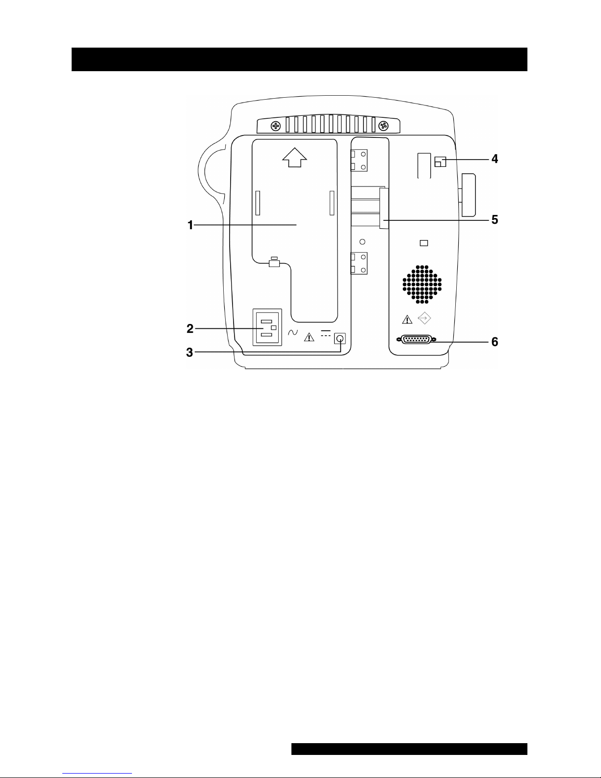
Rear Panel Connections
1 Battery compartment cover: Retains and protects internal
battery.
2 Mains input: Used to connect to AC power supply.
3 External power socket: To be used with approved GE
Medical Systems Information Technologies AC-DC power
converter ONLY.
4 Inactive temperature cable storage: Inactive temperature
probe cable attaches here (Models 200V2 and 400V2).
5 Pole clamp: Used to clamp monitor to pole or stand.
6 Data interface connector: Host communications port
(15 way D-type RS-232 serial port) for use only with
equipment conforming to IEC 601-1, configured to
comply with IEC 601-1-1.
19
Getting Started
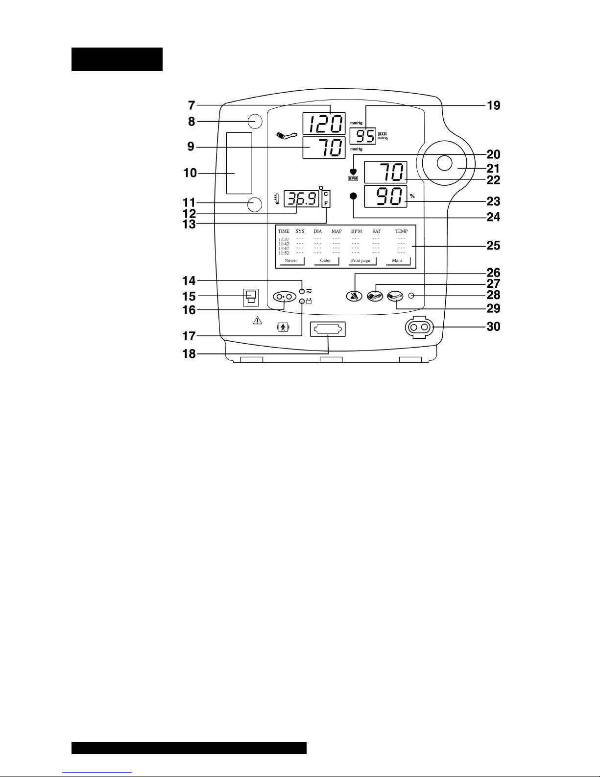
Front Panel Controls and Indicators
7 Systolic pressure display: 3-digit red LED indicates
measured systolic BP in mmHg.
8 Active temperature probe holster: Temperature probe
that is being used stored here (Models 200V2 and
400V2).
9 Diastolic pressure display: 3-digit red LED indicates
measured diastolic BP in mmHg.
10 Temperature probe cover storage: Box of probe covers
stored here (Models 200V2 and 400V2).
11 Inactive temperature probe holster: Extra temperature
probe can be stored here (Models 200V2 and 400V2).
12 Temperature display: 4-digit red LED indicates measured
temperature (Models 200V2 and 400V2).
13 °C °F display: Indicates whether temperature is being
displayed in degrees Celsius or Fahrenheit (Models
200V2 and 400V2).

20
14 External power indicator: Green LED indicates external
power status and battery charging status of monitor.
15 Temperature probe connector: Temperature probe cable
attaches here (Models 200V2 and 400V2).
16 ON/OFF switch: Controls on/off state of monitor; push
for power on and push again for power off.
17 Battery power indicator: Yellow LED indicates operation
and charge status of internal battery.
18 SpO2 sensor connector: SpO2 sensor extension cable
attaches here (Models 300V2 and 400V2).
19 Mean arterial pressure display: 3-digit red LED indicates
measured MAP in mmHg and shows instantaneous cuff
pressure during BP determination.
20 SpO2 pulse indicator: Yellow LED in heart symbol flashes
to indicate that real-time pulse rate measurements are
being derived from SpO2 signals (Models 300V2 and
400V2).
21 Rotor: Used to highlight and select items in LCD menus; if
monitor is off, pressing rotor will switch monitor on.
22 Pulse BPM display: 3-digit yellow LED shows pulse rate in
beats per minute.
23 SpO2 display: 3-digit red LED indicates oxygen saturation
in % (Models 300V2 and 400V2).
24 SpO2 motion/artifact indicator LED: For NELLCOR, LED
Illuminates when motion artifact is detected (Models
300V2 and 400V2). For Masimo, LED illuminates when
low perfusion or low signal quality is detected. (Models
300V2 and 400V2).
25 LCD (liquid crystal display): Displays all alarms, user
interface messages, and configuration options.
26 Alarm silence switch: Alternately mutes and enables
audible alarms; when pushed once after alarm sounds
(silence on), switch lights to indicate that audible alarms
have been silenced for 2 minutes.
27 AUTO BP key: Press to start Auto BP mode.
28 Light sensor: Automatically measures ambient light to set
LED display intensity.
29 START/STOP BP key: Press to start or stop a BP, Auto,
Stat, or Vitals determination.
30 Cuff connector: BP cuff hose attaches here.

21
Getting Started
Switching the Monitor On and Off
To switch the DINAMAP PRO Monitor on, press and hold
the power ON/OFF switch (16) for at least 10 seconds or
press the rotor (21).
As the Monitor powers up, it will run a short self-test routine,
which will flash all the indicator lights and then beep the
warning speaker. After a few seconds the system will be
ready for operation, as indicated by the appearance of the
main menu on the LCD (25).
The Monitor offers an option that allows you to specify the
number of days between monitor maintenance checks
(Preventative Maintenance Reminder [PM]); it also notifies
you when it is time for PM. This option is enabled through
Service mode only (refer to the service manual for
instructions). If the PM feature is enabled and the userselected cycle time has elapsed, a reminder screen appears
upon power up. You can bypass this message to go to the
Main menu by pressing any key on the Monitor.
To switch the Monitor off, push the power ON/OFF switch
(16) again. This will terminate any measurements that may be
in progress and automatically deflate the cuff.
When the Monitor is operating on the internal battery only,
battery life is enhanced by the use of the sleep mode.
However, the PRO Monitor will not enter sleep mode if an
alarm is active. If no controls are used and no determinations
are being made, the Monitor will enter sleep mode after a
time which can be preset by the operator. All LED displays
22
will be blanked except for a dash in the far-left systolic
position, and any existing readings will be transferred to the
LCD, which displays the message “Sleep Mode Active.”
Moving the rotor or pressing a key will “wake up” the
Monitor.
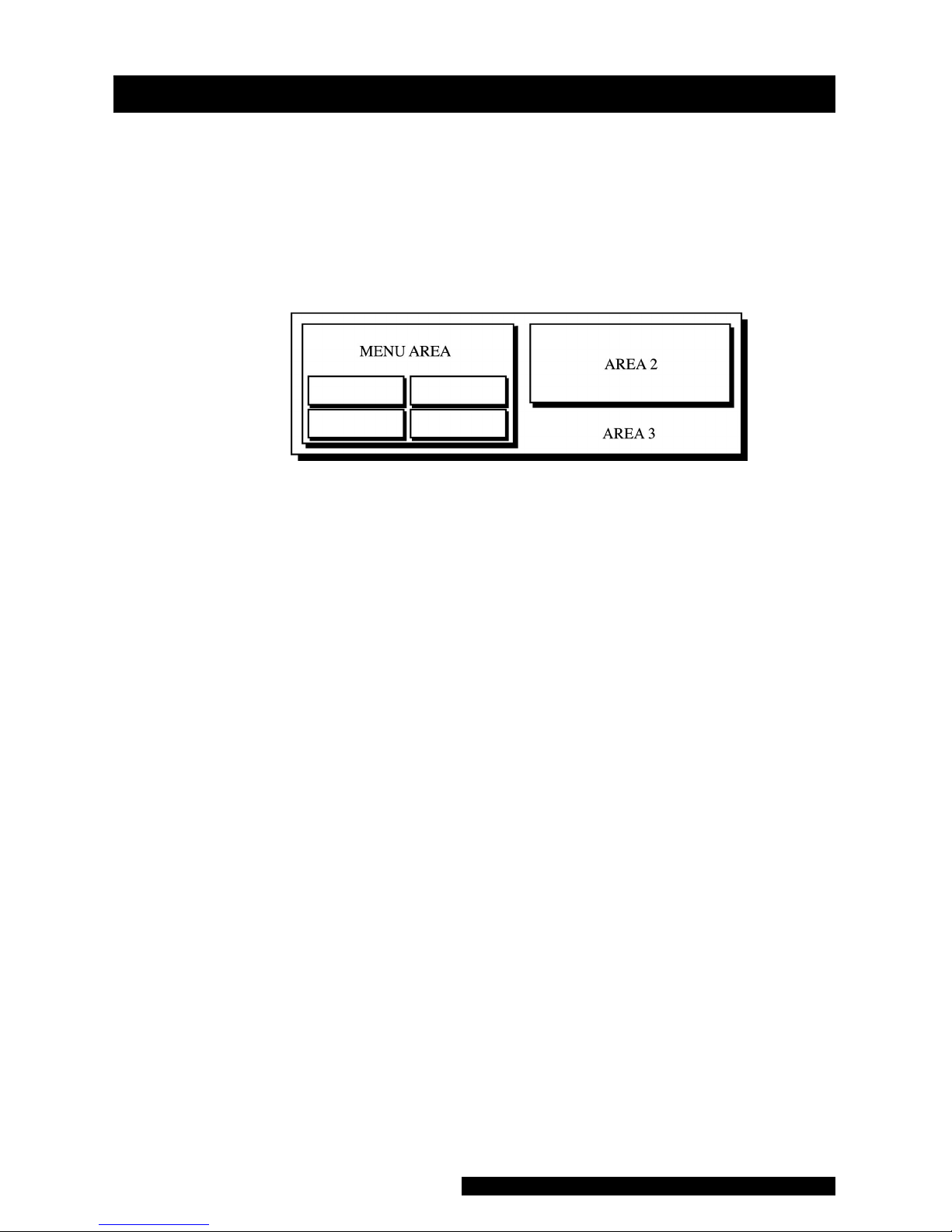
Liquid Crystal Display (LCD)
Menu Area
This area displays the name of the menu that has option
buttons available for selection. Normal text in the menu area
appears dark on a light background, while the text of
selected buttons appears light on a dark background.
Note: Some menus have six option buttons. In these cases,
there is no space available to display the menu title.
Area 2
This area displays data from one of three different sources.
• Source 1: SpO2 plethysmograph (Models 300V2 and
400V2)
• Source 2: Last three BP readings
• Source 3: Error and warning messages
Note: Refer to “Display Button” in the “Using the Menu
System” section for instructions on setting Area 2.
Area 3
This area displays the time, the time lapsed since the last BP
determination, the battery icon (if operating on battery
power, the time and battery icon toggle), and the BP and
Printer modes.
23
Getting Started
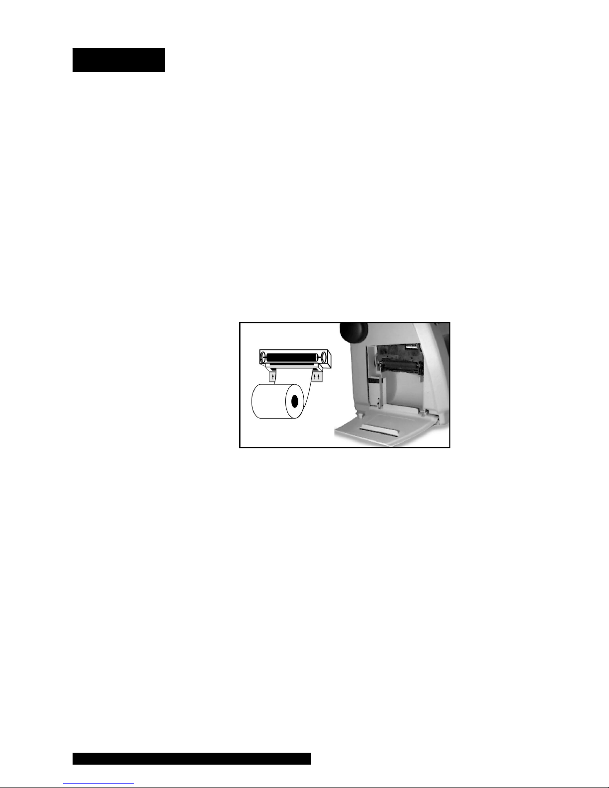
Using the Printer
Installing the Paper
Turn the PRO Monitor so that the side is facing you. While
grasping the side of the Monitor, firmly press the notched
indentations on the printer door to open it. The printer door
will pop open. With the Monitor powered on, place the roll
of paper into the compartment so that the end of the paper
comes off the top, and thread it between the two printer
plates. As the paper touches the plates, the paper will begin
to auto-feed itself into the printer. Feeding the end of the
paper strip through the slot in the door, firmly press the
notched indentation on the side of the printer door to close
it. Use the paper release lever to clear a paper jam or
manually feed the paper.
Note: Make sure that the roll of paper is tightly wound.
Any time the paper is loaded, the printer automatically prints
a test strip with the DINAMAP® PRO name on it. If no print is
visible on the paper, check that the paper roll has been
installed in the correct position (refer to diagram). To tear off
the printout, use a slight sideways action to pull the paper
sharply up across the serrated edge of the door.
Printer Alarms
If the Monitor is switched on with no paper installed or with
the printer door open, the message “No Paper” will appear
next to “PRNT” in Area 3 of the LCD. When new paper is
installed and the printer door is closed, the message will
change to “Manual” for Manual print or “Auto” for Auto
print, depending on the status before the paper change.
If the paper runs out during a print request or if an attempt is
made to print when no paper is installed, the message
“Printer - No Paper” will appear in Area 2 of the LCD and an

24
audible alarm will sound. In addition, the message “No
Paper” will appear next to “PRNT” in Area 3 of the LCD. To
clear the alarm, press the rotor. The message in Area 3 of the
LCD will remain until new paper is installed and the printer
door is closed. (See “Using the Menu System.”)
Installing new paper will cause the DINAMAP PRO header
to be printed, thereby confirming that the paper is installed
correctly and that the printer is operational. The message
next to “PRNT” in Area 3 of the LCD will change to “Auto”
or “Manual” to identify the operating mode of the printer.
After power-off, the operating mode of the printer returns
to the previous user-selected setting (Auto or Manual)
unless specified otherwise in the Print button under the
Service Button.
Storage
Store thermal paper in a cool, dry place. The printed strip
(thermal paper recording) should not be
• exposed to direct sunlight,
• exposed to temperatures over 100 °F/38 °C or relative
humidity over 80%, or
• placed in contact with adhesives, adhesive tapes, or
plasticizers such as those found in all PVC page
protectors.
Note: When in doubt about long-term storage conditions,
store a photocopy of the thermal paper recording.
Cautions
• The paper is thermally activated; therefore, do not store
it in a hot place as discoloration may result.
• Use only replacement paper rolls (58 mm) from GE
Medical Systems Information Technologies.

25
Using the Monitor
Noninvasive Blood Pressure Determination
Description
The BP parameter is included in Models 100V2, 200V2,
300V2, and 400V2. Blood pressure is monitored
noninvasively in the PRO Monitor by the oscillometric
method, which measures the amplitude of the pressure
oscillations within the blood pressure cuff. Further
information about the oscillometric method is in Appendix C.
The PRO Monitor has four BP modes: 1. Manual, 2. Auto,
3. Stat, and 4. Vitals (UK: All Obs). The mode, which is
selected by the user, is shown on the LCD (25). The BP
measurements are automatic, and once the cycle is
complete the LED displays (7, 9, 19, 22) show systolic
pressure, diastolic pressure, mean arterial pressure, and pulse
rate.
1. Manual BP determinations are started by pressing the
START/STOP BP key (29). In the Manual mode, the blood
pressure is determined one time.
2. Auto BP determinations are started by selecting the
AUTO BP key (27) or the Auto button under the Set BP
(UK: BP Mode) button in the Main menu.
When Auto mode is selected, a number at the right of the
Auto button indicates the time interval between each
reading. To change the time interval, choose the box
around the number and turn the rotor until the desired
interval is reached. The interval can be set between 1 and
120 minutes (1, 2, 3, 4, 5, 10, 15, 20, 30, 45, 60, 90, and
120 minutes). Press the rotor to confirm the setting.
3. Stat determinations are started by selecting the Stat
button under the Set BP button (UK: BP Mode) in the
Main menu. In the Stat mode, the blood pressure is
determined as many times as possible in 5 minutes.
4. Vitals (UK: All Obs) determinations are started by
selecting the Vitals (UK: All Obs) button in the Main
menu. (Refer to the “Using the Menu System” section.)
Selection of this button initiates a BP determination while

26
allowing SpO2 and predictive temperature determinations
to be monitored and recorded (depending on Monitor
model). In the Vitals (UK: All Obs) mode, the blood
pressure is determined one time.
Before each BP determination, the Monitor performs a test
to ensure that the cuff pressure is below a specified level.
The determination is delayed until this condition is met.
During the delay, the BP values are displayed as zero.
The Monitor senses the type of hose being used and
automatically uses adult/pediatric monitoring parameters or
neonatal monitoring parameters, as appropriate.
Audible and visible alarms occur when a value for systolic
pressure, diastolic pressure, mean arterial pressure, or pulse
rate is outside the selected high or low limit.
Instructions for cleaning and disinfecting BP cuffs are in
Appendix F.
General Warnings
• The PRO Monitor will not measure blood pressure
effectively on patients who are experiencing seizures or
tremors.
• Arrhythmias will increase the time required by the PRO
Monitor to determine a blood pressure and may extend
the time beyond the capabilities of the Monitor.
• In Manual mode, the PRO Monitor displays the results
of the last blood pressure determination for a duration
of time set by the user or until another determination is
completed. If a patient’s condition changes between
one determination and the next, the Monitor will not
detect the change or indicate an alarm condition.
• Devices that exert pressure on tissue have been
associated with purpura, skin avulsion, compartmental
syndrome, ischemia and/or neuropathy. To minimize
these potential problems, especially when monitoring
at frequent intervals or over extended periods of time,
make sure the cuff is applied appropriately and

27
Using the Monitor
examine the cuff site and the limb distal to the cuff
regularly for signs of impeded blood flow.
• Do not apply external pressure against cuff while
monitoring. Doing so may cause inaccurate blood
pressure values.
• Use care when placing cuff on extremity used to
monitor other patient parameters.
• The PRO Monitor is designed for use only with dualtube cuffs.
• Use only accessories recommended by GE Medical
Systems Information Technologies. Failure to use
recommended accessories may result in inaccurate
readings. See Appendix D.
• Blood pressure cuffs should be removed from the
patient when the Monitor is powered off. If the
extremity remains cuffed under these conditions or if
the interval between blood pressure determinations is
prolonged, the patient’s limb should be observed
frequently and the cuff placement site should be
rotated as needed.
General Cautions
• Accuracy of BP measurement depends on using a cuff
of the proper size. It is essential to measure the
circumference of the limb and to select the proper size
cuff. The air hoses are color-coded according to size of
the patient. The gray 12- or 24-foot hose (3.66 m or 7.3
m) is required on patients who require cuff sizes from
infant through thigh cuffs. The teal (blue-green) 12-foot
hose (3.66 m) is required for the neonatal cuff sizes #1
through #5.
• If it becomes necessary to move the cuff to another
limb, make sure the appropriate size cuff is used.
• The pulse rate derived from a BP determination may
differ from the heart rate derived from an EKG
waveform because the PRO Monitor measures actual
peripheral pulses, not electrical signals or contractions
from the heart. Differences may occur because
electrical signals at the heart occasionally fail to

28
produce a peripheral pulse or the patient may have
poor peripheral perfusion. Also, if a patient’s beat-tobeat pulse amplitude varies significantly (e.g., because
of pulsus alternans, atrial fibrillation, or the use of a
rapid-cycling artificial ventilator), blood pressure and
pulse rate readings can be erratic, and an alternate
measuring method should be used for confirmation.
General Notes
• A patient’s vital signs may vary dramatically during the
use of cardiovascular agents such as those that raise or
lower blood pressure or those that increase or decrease
heart rate.
• Because treatment protocols based on the patient’s
blood pressure may rely on specific values and differing
measurement methods, such as auscultatory, clinicians
should note a possible variance from values obtained
with the PRO Monitor in planning patient care
management. The PRO Monitor values are based on the
oscillometric method of noninvasive blood pressure
measurement and correspond to comparisons with intraaortic values within ANSI /AAMI Standards for accuracy
(a mean difference of ± 5 mmHg, and a standard
deviation of ± 8 mmHg).
• Several conditions may cause the BP parameter to
calculate and display only the mean arterial pressure
(MAP) without a systolic and diastolic reading. These
conditions include very low systolic and amplitude
fluctuations, so an accurate calculation for these values
can’t be made (e.g., patient in shock); too small of a
difference between systolic and MAP calculations in
relationship to the difference between diastolic and
MAP; or a leak has occurred in the PRO Monitor
(1. Check all BP connections 2. Monitor may need
calibration and leak testing). If only the MAP value is
displayed, the systolic and diastolic will display dashes
(---) and an alarm message “N99-BP FAILED” will be
displayed.
 Loading...