

DINA SafeLine DNSL-ZM, SafeLine DNSL-ZMB, SafeLine DNSL-ZMA, SafeLine DNSL-ZMT, SafeLine DNSL-ZMR Product Information
...
SafeLine
Product information
Safety for men
and machines

DlNA Elektronik GmbH
Esslinger Straße 84, 72649 Wolfschlugen
Tel. 07022/95 17-0, Fax 07022/95 17-51
www.dinaelektronik.de,
info@dinaelektronik.de
Quality management system
DQS certificated according to
DIN EN ISO 9001: 2000
Reg.-Nr.67542-01
The direct path to safe automation
DIN EN 62061, SIL CL 3
Two-Hand-Control
according to EN 574: Type IIIC.
(BG-Nr: ET 06146)
IND.CONT.EQ
1 Z D 7
MTTFD: 25 years
DC
awg
: ≥≥≥≥ 99%
CCF according to EN 62061: 2005 85 points
CCF according to ISO 13849-1: 2006 95 points
PFHD = 6,24x10
-8
The total concept of the specified category must
be validated involving the whole control unit.
Variants management
FW
DESIGNER
V404.02x V404.03x
V1.13 x
V1.20 Customer-specific
V1.31 x
V1.32 Customer-specific
V1.38 x
SafeLine DESIGNER Version 1.38B5
SafeLine modules
Central module DNSL-ZM
6 safe digital inputs
4 safe positive switching outputs
2 positive switching outputs, free configurable
1 positive switching output, system ready
V24 interface
Central module DNSL-ZMB
16 safe digital inputs
2 safe positive switching outputs
1 relay output with 2 safe contacts
1 positive switching output, system ready
V24 interface
Dual motion and standstill monitoring
Central module DNSL-ZMT
11 safe digital inputs
5 safe analogue inputs
2 safe positive switching outputs
1 relay output with 2 safe contacts
1 positive switching output, system ready
V24 interface
Dual motion and standstill monitoring
Central module DNSL-ZMR
16 safe digital inputs
4 safe positive switching outputs
2 positive switching outputs, free configurable
1 positive switching output, system ready
Control for the relay outputs module DNSL-KM
V24 interface
Dual motion and standstill monitoring
Central module DNSL-ZMK
6 safe digital inputs
2 safe positive switching outputs
1 relay output with 2 safe contacts
1 positive switching output, system ready
V24 interface
Central module DNSL-ZMA
6 safe digital inputs
1 analogue input
2 safe positive switching outputs
1 positive switching output, system ready
V24 interface
Function modules
Dual standstill, motion and direction monitor
module DNSL-DS, DNSL-DR
8 digital inputs
2 Encoder inputs
4 positive switching semiconductor outputs
DNSL-DR only outputs
Input module DNSL-IN
16 digital inputs
4 positive switching semiconductor outputs
Input / output module
8 digital inputs
10 positive switching semiconductor outputs
Relay module DNSL-RM, DNSL-RM 230
4 relay outputs
8 NO contacts
2 NC contacts only with DNSL-RM
Relay module DNSL-KM
4 safe relay outputs every with 2 safe NO contacts
4 signal contacts
Field busses
Profibus DP DNSL-DP
Interface, 24 byte input and output data,
for diagnostic purpose only
Ether CAT DNSL-EC
Interface, 24 byte input and output data,
for diagnostic purpose only

Product information
Products: safety technology SafeLine redaction 11 date 10.04.09 page 4 from 48
Contents Page
Safety regulations
Intended usage
5
SafeLine: Product description 6
SafeLine DESIGNER 7
DNSL-ZM: Central module 10
DNSL-ZM input usage 10
Outputs usage 11
Special functions RTDS Pulse generator via IF1 11
DNCO Function: Parameter mask
12
Position monitoring of axis with DNSL-DS
12
DNSL-ZMB, DNSL-ZMT: Central modules 13
Inputs usage 13
DNSL-ZMB, DNSL-ZMT: Standstill and motion monitoring 14
DNSL-ZMB, DNSL-ZMT: Output usage RTDS Pulse generator via IF1
DNSL-ZMT: usage of inputs I16 to I20 for safety shutdown mats 15
Parameter mask DNSL-ZMB 15
Parameter mask DNSL-ZMT Memory of application 16
DNSL-ZMR: Central module 17
Inputs usage Inputs usage for standstill and motion monitoring 17
Outputs usage Special functions Description of the wiring layer 17
Parameter mask Memory of application 18
DNSL-PR: Programming device for user application 18
DNSL-KM Relay module 19
Parameter mask Description of wiring layer 19
DNSL-ZMK Central module 20
Inputs usage Outputs usage 20
Special functions Parameter mask 20
DNSL-ZMA: Central module 21
Inputs usage Outputs usage Special functions 21
Parameter mask DNCO Function with „Teach function“ 21
Central modules: Software elements 22
SafeLine settings Password setting SafeLine diagnostic 23
DNSL-DS and DNSL-DR: Standstill, motion and direction monitoring 25
DNSL-DS, DNSL-DR inputs usage 25
DNSL-DS and DNSL-DR: Function of standstill, motion and direction monitoring 26
Monitoring of the drive break 26
DNSL-DS and DNSL-DR: Measuring system (encoder) requirements for speed monitoring. 26
Input frequency at the resolver input. 26
DNSL-DS, DNSL-DR: DNCO function Input selection for DNCO Function Usage of DNCO function 27
Usage of the outputs Mask of parameter 28
DNSL-IN: Input module Inputs usage 29
Output usage Parameter mask 30
DNSL-IO: Input/ output module Inputs usage 31
Outputs usage 32
Parameter mask 33
DNSL-RM, DNSL-RM 230: Relay modules 34
Outputs usage Parameter mask 34
Field BUS: DNSL-DP Profibus DP and DNSL-EC Ether CAT 35
Field BUS parameter mask Spindle activation and deactivation: 35
Virtual wiring Example: Field BUS virtual wiring of input data bit to the field bus Master 36
Field bus: Virtual wiring of output data from field bus Master Field BUS communication 37
Dimension diagram and assembling 38
General technical data 39
DNSL-ZM 39
DNSL-ZMB, DNSL-ZMT DNSL-ZMA, DNSL-ZMK DNSL-ZMR 40
DNSL-DS, DNSL-DR DNSL-IN DNSL-IO 41
DNSL-RM DNSL-RM 230 DNSL-KM 42
Error massage DESIGNER 44
Certificate 46

Product information
Products: safety technology SafeLine redaction 11 date 10.04.09 page 5 from 48
Safety regulations
• The unit may only be installed and operated by those who are qualified electrical engineers or have received sufficient
training and are familiar with both these instructions and the current regulations for safety at work and accident prevention.
Follow VDE, EN as well as local regulations especially as regards preventative measures!
• Ignoring the safety regulations can lead to death, serious injury or cause considerable damage!
• In emergency stop applications use the internal function “Speed output restart disable” or a higher level control unit must
ensure that the machine cannot start up again automatically!
• Transport, storage and operating conditions should all conform to EN 60068-2-1, 2-2. See technical details
• Any guarantee is void following unauthorised modifications. This can lead to death, serious injury or cause considerable
damage!
• The unit should be cabinet mounted, otherwise dampness or dust could lead to functional impairment.
• Adequate fuse protection must be provided on all output contacts especially with capacitive and
inductive loads.
• The unit must be installed following the specification of DIN EN 50274, VDE 0660-514 regarding the required distances.
• During operation, parts of the electronic switchgear carry high voltage.
• DANGER! During operation the protective covers must not be removed from the electronic switchgear!
• The device must always be replaced after the first malfunction!
• The unit must be disposed of properly when it reaches the end of it service life.
• Keep the operating instructions!
Intended usage
The SAFELINE series is a product with safety-relevant functions for machines and equipments.
With this product the most diverse functions at machinery can be supervised and/or steered.
Testing basis:
• 2006/95/EWG „guidelines of low voltage usage"
• 2004/108/EG „EMC-guidelines“, EN55011+A1, EN61000-6-2
EN 61496-1-2, VDE 0113-201 non contact protection device „BWS- interference immunity"
GS-ET-20: Principles for testing and certification of relay safety combinations"
DIN EN 62061 „Safety of machinery”, (VDE 0113-50)
DIN EN 61508-part3 „Principles for computers in safety systems “
The safety outputs correspond to DIN EN 62061, SIL CL 3, VDE 0113-50
As a motion monitor according to EN 60 204-1 /VDE 0113 part 1 corresponding to DIN EN 62061, SIL CL 3, VDE 0113-50.
As a standstill monitor according to EN 60 204-1/ VDE 0113 Part 1 corresponding to DIN EN 62061, SIL CL 3, VDE 0113-
50.
As logic unit for two-hand control function according to EN 574: Type III C (BG No.: ET 06146).
The analogue inputs (I16 to I20) are also used with a safety shutdown mat, only type TS/ W1 and TS/ BK1/ Fa. Mayser
The products are according to the requirements of the updated standards, which are listed in this document.
Product information
Products: safety technology SafeLine redaction 11 date 10.04.09 page 6 from 48
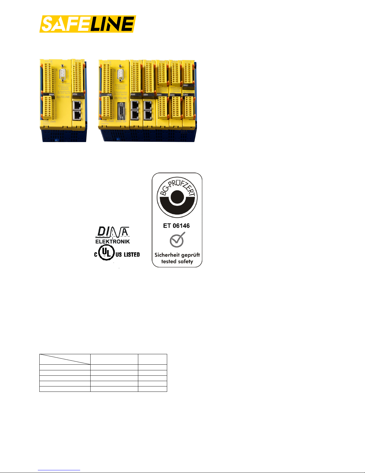
SafeLine: Product description
SafeLine is housed in a metal rack type enclosure. It can be mounted by spring fasteners to a DIN rail. The individual functional modules are pluggable. The equipment is available in different housing sizes, depending on the
number of functional modules to be used. Up to 15 functional modules may be used. Racks with 3, 5, 7, 9, 13
and15 slots are available. Unused slots are covered with a blind cover. (Article No. 10BD00) All modules are
plugged into the redundant backplane bus system. The device is programmed using the SafeLine DESIGNER program on a PC.
To cover the requirements of a wide range of applications, different function modules are available.
The status of all I/O clamps and supply voltages is indicated by corresponding LED.
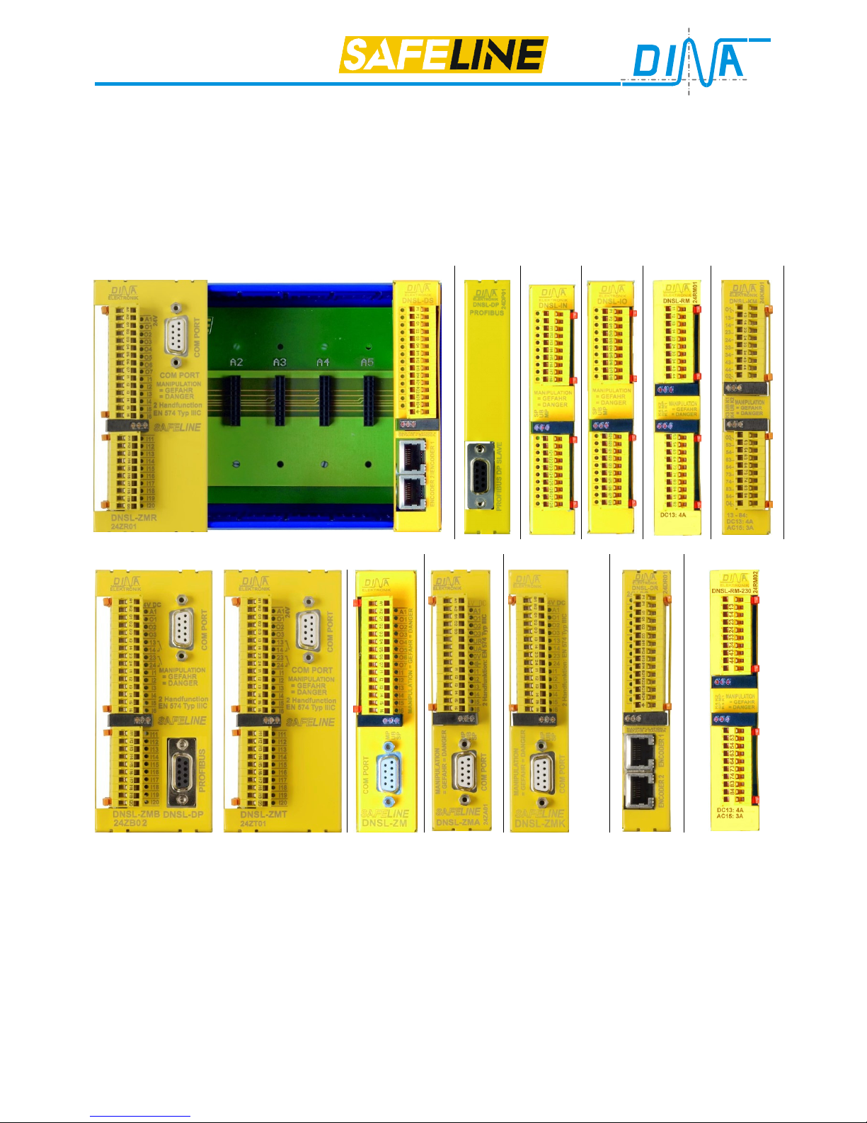
Central module Rack Function modules
DNSL-ZMR Rack DNSL-DS DNSL-DP DNSL-IN DNSL-IO DNSL-RM DNSL-KM
Central modules Function modules
DNSL-ZMB-DP DNSL-ZMT DNSL-ZM DNSL-ZMA DNSL-ZMK DNSL-DR DNSL-RM 230
DNSL-ZMB, ZMT and ZMR optional with PROFIBUS
The central module will always be put into slot 1. (Leftmost slot in the rack) The PROFIBUS module DNSL-DP must
be placed next. All other modules may be placed in any order.
The module DNSL-ZMB, ZMT and ZMR require 2 slots.
DNSL-ZMB, ZMT and ZMR are available with integrated PROFIBUS module DNSL-DP.
See picture of ZMB, ZMT on the left!
The relay module DNSL-KM can only be used by central module DNSL-ZMR and must be placed next.
Interfaces
The COM PORT interface is used to transfer data between the PC SafeLine Designer Program and SafeLine.
The used connection cable has to be V24 (1:1). Pin 2, 3 and 5 in the cable are important.
The PROFIBUS interface DNSL-DP is used to transfer data between the PROFIBUS DP Master and SafeLine.
Indicators
The middle LED at the black LED-Block indicates the supply voltage is present, the left and right LED indicate that
the module is ready.
Product information
Products: safety technology SafeLine redaction 11 date 10.04.09 page 7 from 48
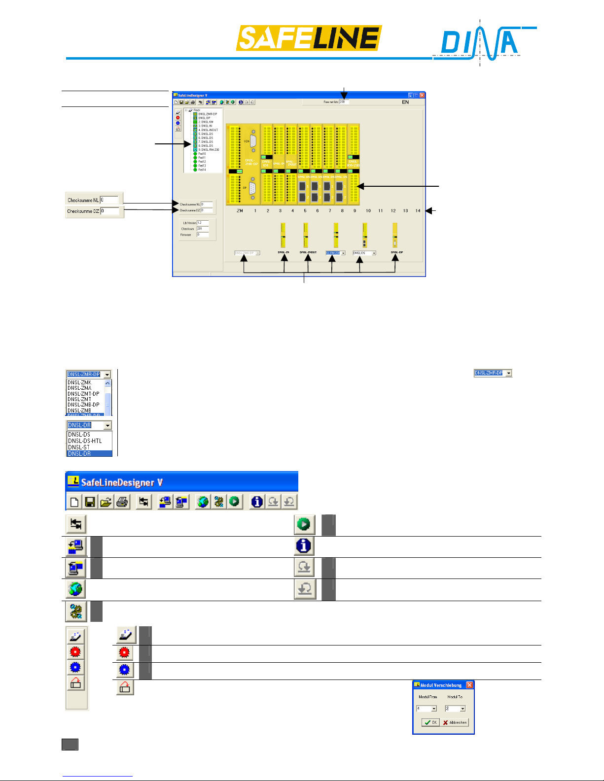
SafeLine DESIGNER
1. layer: Module layer
Free circuit
Selection Menu
used modules
net list
motion control
parameter
Layer 2 (parameter
mask) will be displayed
by right click with
mouse on the individual
module.
Position of modules
Module selection
The central module will always be put at slot ZM. The field bus module DNSL-DP or DNSL-EC must be placed
next. All other modules may be placed in any order. Only one central module and one PROFIBUS module can be
used. Function modules can be several.
The central module DNSL-ZMB, ZMT and ZMR need 2 slot. If one of them will be selected, the next slot will be
barred.
To place the module DNSL-IN, INOUT and DP: move the mouse to the module. Press the left mouse-button and
hold it down, than move the mouse to the wished position at the area above left and release the mouse-button.
Module with variants: Modules with different variants show a selection area(example ).
Click the downward arrow button with the left mouse-button. The variants will be displayed. Select the
wished variant with a click.
After a selection of a variant of central module an other window will be displayed. Click OK. The module will be automatically placed at slot position 0.
After a selection of a function module the module will be placed above the selection area. move the
mouse to the module. Press the left mouse-button and hold it down, than move the mouse to the
wished position at the area above left and release the mouse-button.
Menu description
To change between module and wiring
layer
To change to layer diagnostic
Transfer of data from PC to SafeLine
Information of DESIGNER and Firmware
Transfer of data from SafeLine to PC
Export of net list from SafeLine and PROFIBUS
Language selection
Import of net list from SafeLine and PROFIBUS
To change to layer 2 (parameter layer)
Parameter file history
Actual error list
saved error list
To change module position
Click at arrow left to select the actual position.
Click at arrow right to select the new position.
After click OK.
The function of these buttons is only possible, if there is a connection for data transfer to SafeLine.
Product information
Products: safety technology SafeLine redaction 11 date 10.04.09 page 8 from 48
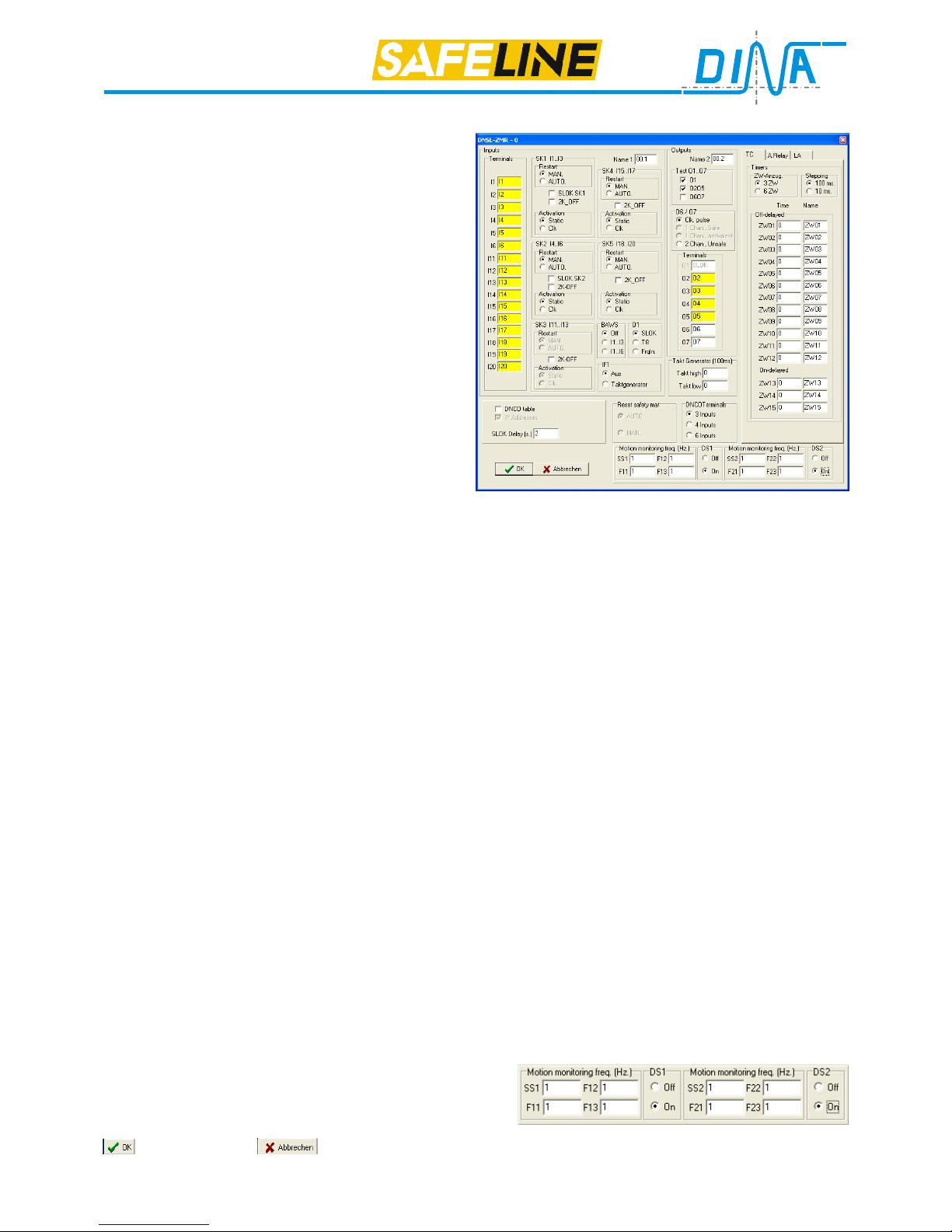
2. layer: Parameter mask
Selection timer(TC)
Central module parameter mask
Inputs, terminal: labelling of inputs I1 to I20
SK1 I1..I3, SK2 I4..I6, Restart: SK*-Restart „manually“
by activating Q or „Auto.“ automatically
SLOK SK1, SLOK SK2: the function SLOK SK1 and
SLOK SK2 is only important, if:
1. SK1 I1..I3 or SK2 I4..I6 as Emergency stop safety
circuit is used.
2. an external sensor or internal SafeLine error is
existed.
After SafeLine forces an emergency stop function like
the actuating of the emergency-stop button.
The forced emergency stop stopped the plant.
SafeLine works normally till the end of the SLOK Delay
time. After all outputs of SafeLine will be turned off.
The SLOK Delay time has to be selected such so long,
that the plant will be stopped safety.
2K_OFF: If it is activated and Restart AUTO is selected, no switch off/on of the circuit contact is necessary for test after power off/on. By Restart MAN a quit
signal is necessary.
If 2K_OFF is not activated a switch off/on of the contact is necessary after power off/on. By Restart MAN a quit
signal is necessary.
SK Activation: Safety circuit via static or clock signal (cross-circuiting detection)
Name 1: Labelling of the inputs
BAWS: Operation mode 3 or 6 switch positions via 3 or 6 inputs
O1: SLOK: Output of operating state, T8: semiconductor output
FrqIn: frequency input for motion control only possible with DNSL-ZMT, ZMB, ZMR and field bus module
Test O1..O7: The internal check of the outputs O1, O2 till O5 and O6, O7 can be turned off and on.
The function „check turned off“ the outputs will not tested.
This feature is possible for all semiconductor outputs at all central modules.
TC, A. Relay, LA: Change between time delay relays, auxiliary relays and logic modules. See below.
Timers, ZW-Anzug: selection 3 or 6 on-delayed timers
Timers, Stepping: „100ms“ time domain 100ms to 999,9s „10ms“time domain 10ms to 99,9s
Off-delayed, on-delayed:
Fields left: Entry of time value, 10 = 1s with selection 100ms, 10 = 100ms with selection 10ms
Fields right: Entry of the name of time delay.
Terminals O2 to O7: fields for entry the name of the outputs.
DNCO Table: If this function will be selected, a mask with two tables for frequency values will be appear. Every
table includes fields for 48 values. The frequency values assign the motions, that have be monitored.
See DNSL-DS.
DNCO Terminals: The number of the monitored motions defines the necessary inputs at the central module or
DNSL-DS. Eight motions need 3 inputs, 16 motions need four inputs and 48 motions need 6 inputs.
IF1: With the selection „ON” the function of a pulse generator (Takt Generator) is possible via the virtual contact
IF1. IF1 can be used to control an hardware output.
Takt Generator(100ms): The time of the signal „High“ and the signal „Low“ can be defined. The stepping is
100ms. 1 = 100ms, 10 = 1s etc.
SLOK Delay [s]: If there is a defect in SafeLine or in the sensor system of SafeLine the output 01 will be turn off.
After an adjustable delay time 0 to 25s all outputs at SafeLine will be turn off. For the time length please take care
for the function SLOK SK1 or SLOK SK2
DS1, DS2: With the central module there are two motion and standstill controls for two drives possible.
The sensors for the motion and standstill controls can be proximity switches. For a motion control there are two
proximity switches with 24V signals necessary. With the selection is this function available.
The input IN11 to IN14 are used for this function at the central module DNSL-ZMB, ZMT and ZMR.
Motion monitoring freq. [Hz];
SS1, SS2: Entry the frequency value for standstill
F11, F21: Entry the frequency value for tool setting mode
F12, F22: Entry the frequency value for semiautomatic mode
F13, F23: Entry the frequency value for automatic mode
: save and close. : close without saving.
*)SK: Safety circuit
Product information
Products: safety technology SafeLine redaction 11 date 10.04.09 page 9 from 48
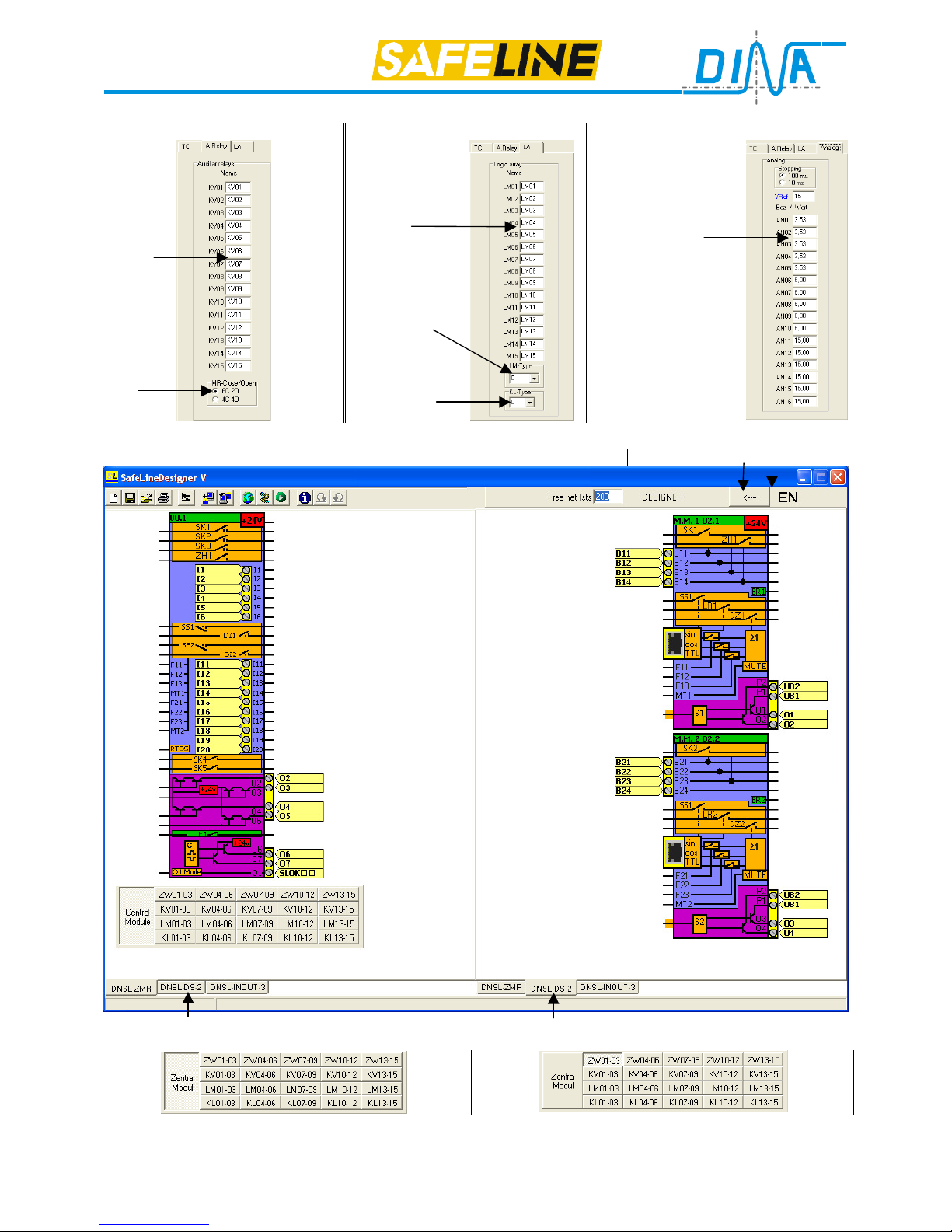
Central module: selection A. relay, LM or Analogue
Selection A. Relay, Contactor relay Selection (LM), logic modules Selection Analogue only with ZMT/ZMA
Fields for
labelling
Contact
definition
Fields for
labelling
Selection of
logic module
type
Selection of
custom logic
module
Vref: Reference voltage 15V,
produced in
SafeLine.
Fields to enter the
voltage value
Trigger points at ZMT,
Tension values at
ZMA
3. layer: Wiring layer
Graphic to lift side language
Button to select the modules at the wiring layer. The module can be selected left or right, depending from the used button
The cipher at the end of the button is the position number in the rack.
Button to select the time delay relay (ZW), contactor relay (KV) or logic modules (LM) at the wiring layer, if the central
module is chosen. The module can be selected left or right, depending from the used button.
Product information
Products: safety technology SafeLine redaction 11 date 10.04.09 page 10 from 48
DNSL-ZM: Central module
Every unit contains only one central module.
The number of function modules is dependent on the application.
Programming of the SafeLine unit is accomplished with the SafeLine Designer program on a PC. The completed
program is transferred via the COM interface to the Safeline unit.
The SafeLine DESIGNER is special software developed by DINA Elektronik.
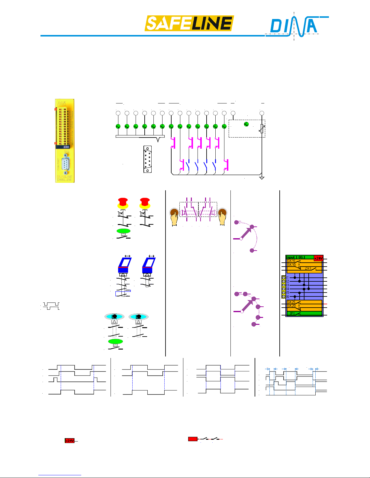
The operation voltage (24V DC) is supplied to the clamps A1 und A2.
DNSL-ZM Connection scheme DNSL-ZM
O5
V24
COM PORT
Netzteil
Power supply
UB = 24V DC
I1I2I3I4I5I6 O1O2O3O4O6O7 A2 A1
0V
24V intern
6A
Eingänge / Inputs Ausgänge / Outputs
24V DC
DNSL-ZM input usage
Safety circuit 1 (SK1)
E1⇒I1
E2⇒I2 and
Q ⇒I3
control SK1S and
SK1Ö
Safety circuit 2 (SK2)
E1⇒I4
E2⇒I5 and
Q ⇒I6
control SK2S und
SK2Ö
E1 and E2 may be
used in static or
clocked mode.
E1
E2
All inputs may be used
for optional functions.
Emergency Stop
E1
E2
E1
E2
Q
Quit
manually automatic
Protection cover function
E1
E2
11 12
21 22
E1
E2
Q
11 12
21 22
13 14
23 24
automatic
Permission function
Q
E2
E1
Quit
E2
E1
manually automatic
Two-hand function
Q1E1Q2
E2
only by
E1⇒I1
Q1⇒I2
E2⇒I3
Q2⇒I4
control ZH1
Static input signal only
According EN 574:
Type IIIC
Operation mode
Switch (BAWS)
One from three
24V
DC
BA/ Mode
1
2
3
I1 to I3
One from six
24V
DC
BA / Mode
2
3
4
5
6
1
I1 to I6
DNCO Function
See page 12
and DNSL-DS
Wiring Layer
manually
automatic
Protection cover function
Two-hand function
E1
E2
Q
SK1S, 2S
E1
E2
SK1S, 2S
Q
E1
E2
SK1S, S2
Q2
E1
E2
ZH1
Q1
>500ms Q2
OK
<500ms
The static/ clocked and manually / automatic operation mode of SK1 and SK2 are defined in the parameter
mask. In manual mode, restart is only possible using Q.
Note: „automatic“ should be selected in the DESIGNER, if protection cover switch with quit contact is used. The
quit contact has to be connected to I3 respectively I6. “automatic“ should be selected in the DESIGNER, if there
are safety circuits without quit contact. I3 respectively I6 has to be connected to 24V DC.
SK1S, SK2S will be wired into the safety chain with the DESIGNER. The left side of the 1st contact must be con-
nected to
, the right side connects to the next contact.
SK1
SK2
+24V
. SK1S, SK1Ö, SK2S, SK2Ö and ZH1 are
virtual redundant Contacts. Two safety circuits or one Two-hand-function are possible.
The inputs may also be used as general-purpose inputs.

Product information
Products: safety technology SafeLine redaction 11 date 10.04.09 page 11 from 48
Outputs usage
1. Output O1 function may be defined in the parameter layer to one of the following:
SLOK: Output indicating System Ready
T8: Semi conductor switch
2. FrqIn: possible only with DNSL-ZMB, ZMT and ZMR
3. O2, O3, O4 and O5 are redundant outputs made of a positive switching semiconductor and a relay contact. These outputs may be activated directly by external inputs or by virtual connections from NC, NO, Logic-elements, time delay relays etc. The wiring is done by the virtual control inputs in the DESIGNER.
4. O6 and O7 are free usable outputs. The usage may be defined in the parameter
layer to the following:
Clock output supply for cross-circuiting detection in safety circuits,
E1
E2
No virtual wiring possible
Single outputs individually activated by T6, T7
Note: T6 and T7 only visible, if this mode is selected in the
parameter layer.
Paired output Safe output to duplicate dual channel contacts.
Activated by S1 and Q
Q may be wired to virtual 24V directly or can be used from an external input.
S1 and Q are only visible, if this mode is selected in the parameter layer.
The 24 V supply for the outputs O1 – O7 is from the A1 input clamp.
Note: All semiconductor outputs will be monitored constantly for wrong behaviour
independent of the function. If an error is detected on one of the outputs, all outputs
will be switched off after an adjustable time delay (0-25s).
Wiring layer
Special functions
RTDS
Virtual input to reset the interlock of the virtual contacts of the motion control module DNSL-DS, and DNSL-DR
after the actual values are below the limit values. The virtual input RTDS must be held at 24V for more then 500ms.
For this function a hardware input or virtual output can be used.
Pulse generator via IF1
With the selection „ON” via the parameter mask the function of a pulse generator (Takt Generator) is possible via
the virtual contact IF1. The right connection can be used to control an hardware output, the left to virtual
The time of the signal „High“ and the signal „Low“ can be defined. The stepping is 100ms. 1 = 100ms, 10 = 1s etc.
Note: in the SAFELINE unit all digital inputs are processed by both channels and checked for Plausibility. There
is no single channel processing.
Malfunctions
Behavior: Output O1 switched off. LED- for O1 not illuminated.
Left LED at ZM Block not on. Right LED at Block blinks sequence short/long.
Correction: Check of the wiring
Check of the configuration (wrong assembly of the rack or wrong project planning.)
Reset stored errors by switching 24V supply OFF and ON.
Product information
Products: safety technology SafeLine redaction 11 date 10.04.09 page 12 from 48
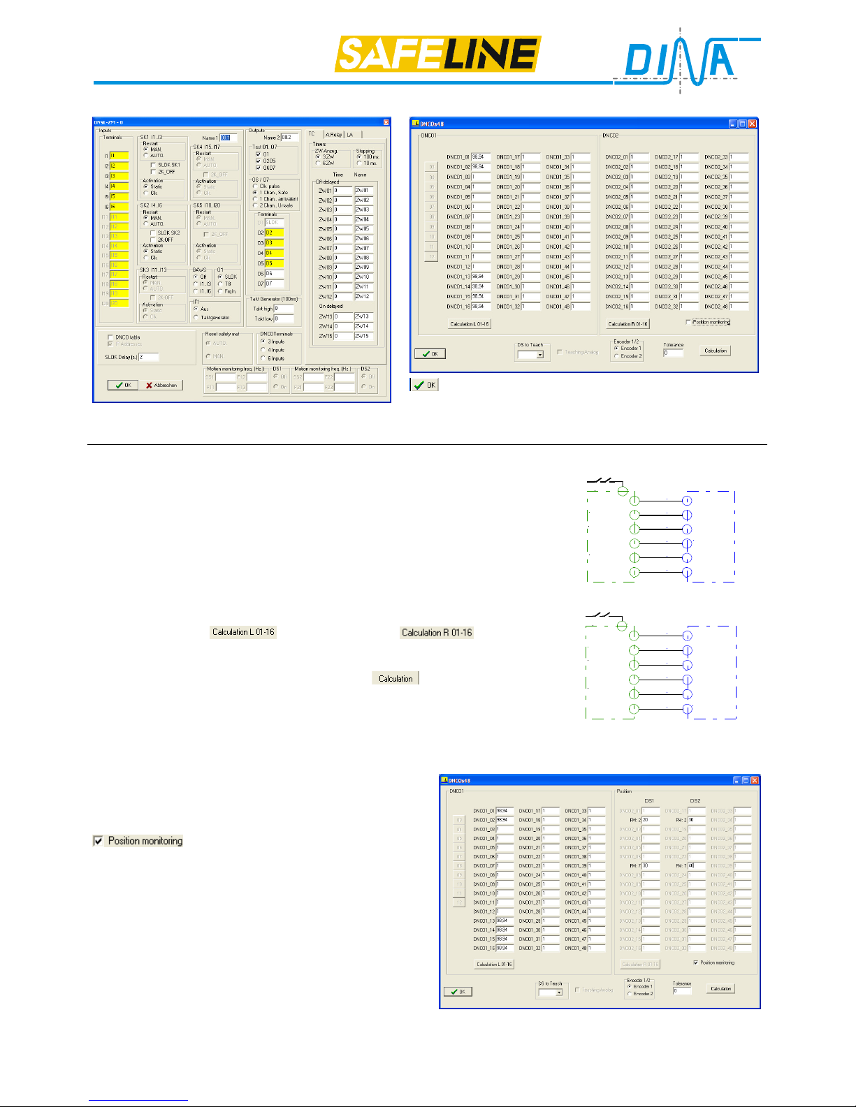
Parameter mask DNCO Parameter mask
: Mask save and close.
Selecting DNCO mask is available in every central module mask.
Description of the parameter mask: See page 8 and 9.
DNCO function: Parameter mask
Two frequency tables containing up to 48 values each.
These values define the maximum monitored speeds. This frequency values
are the frequencies of the encoder of the drive measurement system by the
corresponding speed.
Monitoring 8, 16 or 48 speed’s is possible and can be selected via the central
module mask “DNCO Terminals”. The necessary inputs to select one from 8,
16 or 48 speeds can be used at the central module or at the motion monitoring
module DNSL-DS. For 8 value there are 3 input necessary, for 16 value 4
inputs and for 48 value 6 inputs.
A frequency value has to be entered in every field of the selected table.
With the selection 16 the frequency value 01 to 15 can be automatically calculated, if the maximal value in field DNCO1_16 is entered.
After this the button for the left table and for the right
have to be activated.
A %-value (0 to 20%) can be sum up to all value in the table, if in the field
“Tolerance” a value was entered and the button
will be activated.
For every frequency table the encoder input at motion monitoring equipment
has to be defined. The selection has to be done vie Encoder1/2.
DS to Teach: For this function see DNSL-ZMA.
Example:
DNCO1 table via DNSL-DS
D1
B11
D2
D3
D4
D5
D6
B12
B13
B14
B21
B22
DNSL-DS
DNCO1
SH-K
TK
Steuergerät
Control
device
DNCO2 table via central module
D1
I1
D2
D3
D4
D5
D6
I2
I3
I4
I5
I6
DNSL-ZM
ZMB
ZMT
ZMA
ZMK
ZMR
DNCO1
SH-K
TK
Steuergerät
Control
device
Position monitoring of axis with DNSL-DS
Usage DNCO mask for the configuration
The right side of the mask is used for the position monitoring.
The motion control DNSL-DS, DR is able to monitor the
position of axis. This function has to be selected with
. After the message “DNCO Data will be
cleared. continue?” It has to be confirmed with yes or no.
The DESIGNER sense the rack position of the function
modules (FM) DNSL-DS or DNSL-DR. 14 function modules are possible.
Every motion control has two position monitorings. In the
fields beside FM the increments number of the encoder
can be written.
Always if no function modes are selected and the axis
stop, DNSL-DS, DR record this position as the new monitored position.
The monitored axis can oscillate lift and right but not more than these predetermined increments. If it decrease, the
virtual contact SS1 or SS2 in the wiring layer opens.
Notice: If position is monitored, no standstill monitoring is possible.
Product information
Products: safety technology SafeLine redaction 11 date 10.04.09 page 13 from 48
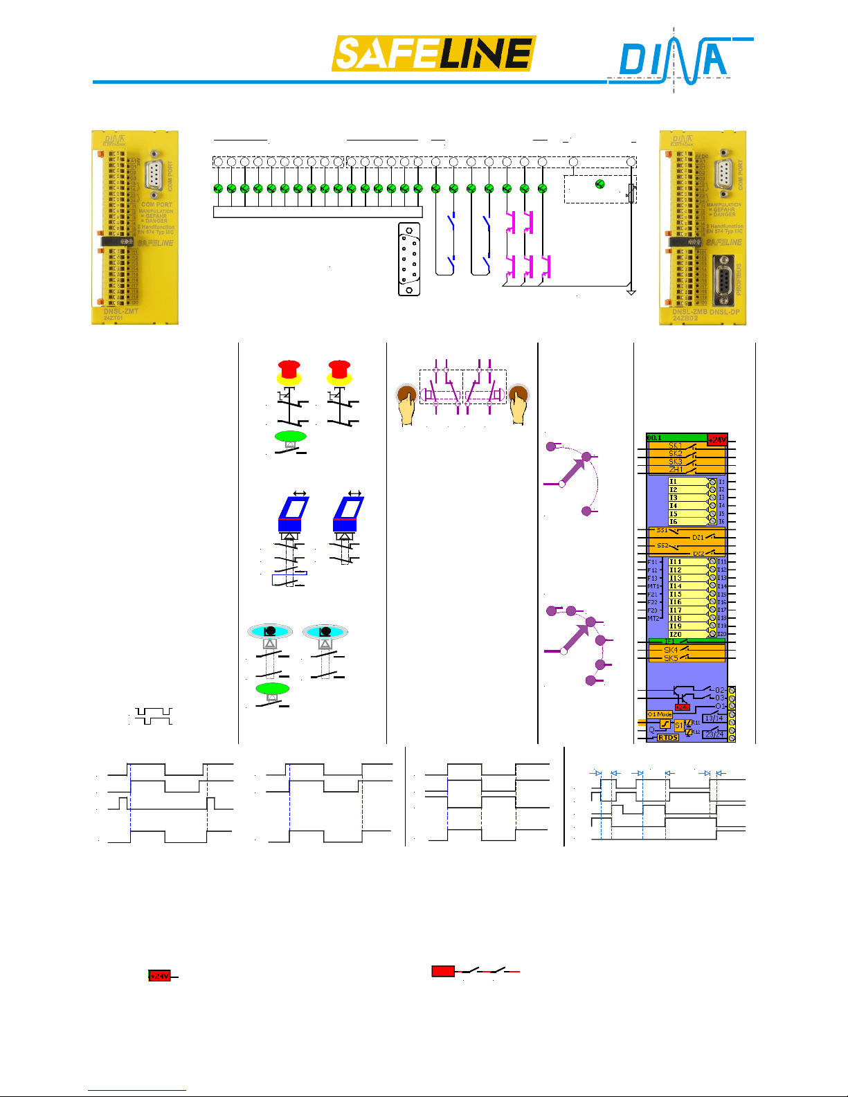
Central modules DNSL-ZMB, DNSL-ZMT
DNSL-ZMT
Schematic
14
V24
COM PORT
Netzteil
Power supply
24V DC
I1I2I3I4I5I20 O1O2O3132324 A2 A1
0V
24V intern
6A
I19 I18 I17 I16 I15 I14 I13 I12 I11 I6
Eingänge / Inputs
Ausgänge / Outputs
UB = 24V DC
DNSL-ZMB and ZMT can be ordered with an integrated field bus, Profibus or Ether cat
module. Type with Profibus: DNSL-ZMB-DP, type with Ether cat: DNSL-ZMB-EC
DNSL-ZMB-DP
DNSL-ZMB, DNSL-ZMT: Inputs usage
Safety circuit 1 (SK1)
E1⇒I1
E2⇒I2
Q ⇒I3 controls SK1
Safety circuit 2 (SK2)
E1⇒I4
E2⇒I5
Q ⇒I6 controls SK2
Safety circuit 3 (SK3)
E1⇒I11
E2⇒I12
Q ⇒I13 controls SK3
Only at ZMB
Safety circuit 4 (SK4)
E1⇒I15
E2⇒I16
Q ⇒I17 controls SK4
Safety circuit 5 (SK5)
E1⇒I18
E2⇒I19
Q ⇒I20 controls SK5
E1 and E2 may be used
in static or clocked
mode.
E1
E2
Emergency Stop
E1
E2
E1
E2
Q
Quit
manually automatic
Protection cover function.
E1
E2
11 12
21 22
E1
E2
Q
11 12
21 22
13 14
23 24
automatic
Permission function
Q
E2
E1
Quit
E2
E1
manually automatic
Two-hand function
Q1E1Q2
E2
Only by
E1⇒I1
Q1⇒I2
E2⇒I3
Q2⇒I4
control ZH1
Static input signal only
According EN 574:
Type IIIC
Operation
mode Switch
(BAWS)
One from
three
24V
DC
BA/ Mode
1
2
3
I1 to I3
One from six
24V
DC
BA / Mode
2
3
4
5
6
1
I1 to I6
DNCO function
See page 27
or click here
DNSL-DS
Programming Layer
manually automatic
Protection cover function
Two-hand function
Q
E1
E2
SK1-5
E1
E2
SK1-5
Q
E1
E2
SK1-5
Q2
E1
E2
ZH1
Q1
>500ms Q2
OK
<500ms
The static/ clocked and manually / automatic operation mode are defined in the parameter mask. In manual
mode, restart is only possible using Q.
Note: „automatic“ should be selected in the DESIGNER, if protection cover switch with quit contact is used. The
quit contact has to be connected to I3, I6, I13, I17 respectively I20.
“automatic“ should be selected in the DESIGNER, if there are safety circuits without quit contact. I3, I6, I13, I17
respectively I20 has to be connected to 24V DC.
All inputs may be used for optional functions.
SK1 to SK5 will be wired into the safety chain with the DESIGNER. The left side of the 1st contact must be con-
nected to
, the right side connects to the next contact.
SK1
SK2
+24V
. SK1 to SK5 and ZH1 are virtual redun-
dant contacts. Five safety circuits or one Two-hand function and three safety circuits are possible.
These inputs may also be used as general-purpose inputs.

Product information
Products: safety technology SafeLine redaction 11 date 10.04.09 page 14 from 48
DNSL-ZMB, DNSL-ZMT: Standstill and motion monitoring
The Central module DNSL-ZMB may be used to monitor two motions for safe standstill and safe speed. For speed
sensing at a motion two proximity switches could be used. This Function is also with DNSL-ZMR available.
Inputs
Operation mode Virtual
Inputs
Examples
Wiring layer
Monitoring 1
Sensor (S1)⇒I11
Sensor (S2)⇒I12
Monitoring 2
Sensor (S3)⇒I13
Sensor (S4)⇒I14
Tool setting mode BA2
Semi automatic mode BA3
Automatic mode BA1
Not-monitored BA1
Tool setting mode BA2
Semi automatic mode BA3
Automatic mode BA1
Not monitored BA1
F11⇒
F12⇒
F13⇒
MT1⇒
F21⇒
F22⇒
F23⇒
MT1⇒
Tip contact
Permission contact
Protection cover contact
Protection cover contact
Tip contact
Permission contact
Protection cover contact
Protection cover contact
S1
S2
S3
S4
Zahnrad
Gear
Zahnrad
Gear
Monitoring 1
Monitoring 2
SS1 virtual contact for standstill: closed if standstill, open if
νννν
act >
νννν
standstill
DZ1 virtual contact for
νννν
max: closed if
νννν
act <
νννν
max , open if
νννν
act > νmax
SS2 virtual contact for standstill: closed if standstill, open if
νννν
act >
νννν
standstill
DZ2 virtual contact for
νννν
max: closed if
νννν
act <
νννν
max , open if
νννν
act > νmax
To use motion monitoring the function DS1 and/or DS2 in the SafeLine DESIGNER must be selected.
I11, I12 and I13 are not available for safety circuits in this case.
Selection of the individual speeds is accomplished by entering the corresponding frequency in Hz into the parameter fields. The maximum Input-frequency for I11 – I14 is 1200Hz.
Proximity switches requirements:
2 signals with 180° phase offset. One switch at the cog the an other at the gap. Positive switched to 24V DC (PNP)
DNSL-ZMB, DNSL-ZMT: Output usage
Output O1 function may be defined in the parameter layer to one of the following:
SLOK: Output indicating system ready
T8: Semi conductor switch
FrqIn: Frequency input (maximal 1200Hz) single channel motion control.
The output O1 can be redefined as frequency input in the parameter layer to function
as a one-channel not safe motion control. As impulse device a proximity switch may
be used.
Setting the value for the motion control will be done using the PROFIBUS.
The proceeding of programming is received by DINA Elektronik.
SS2 virtual contact is closed at standstill and opened at
νννν
act >
νννν
standstill
DZ2 virtual contact is closed at
νννν
act <
νννν
max and opened at
νννν
act > νmax
To reset the contact DZ2 the maximum of the speed has to be decreased more than
10% a the virtual input RTDS has to be switched to virtual 24V.
Programming Layer
O2 and O3 are redundant outputs made of two positive switching semiconductors. These outputs may be activated
directly by external inputs or by virtual connections from NC, NO, logic elements, time relays etc.
R13/R14, R23/R24 are 2 relay outputs and they are configurable to the following:
a) two independent NO contacts, safety category 2, activated by K1, K2
b) two redundant NO contacts, safety category 4, activated by S1 and Q.
Q may be connected to or connected via an external input. S1 and Q are displayed in the programming layer
only in this mode.
Version a and b will be factory-made. The factory-made configuration has to be selected via the parameter mask.
Note: All outputs will be monitored constantly for wrong behavior independent of the function. If an error is detected on one of the outputs, all outputs will be switched off.
Special function:
RTDS: Virtual input to reset the interlock of the virtual contacts of the motion control at the central mod-
ule and DNSL-DS, DR after the actual values are below the limit values. This virtual input can be also used to reset
safety shutdown mat. The virtual input RTDS must be held at virtual 24V for more then 500ms. For this function a
hardware input I1-I6, I11, I12 rather a hardware input at a function module or virtual output can be used.
Pulse generator via IF1:
With the selection „ON” via the parameter mask the function of a pulse generator (Takt Generator) is possible via
the virtual contact IF1. The right connection can be used to control an hardware output, the left to virtual
The time of the signal „High“ and the signal „Low“ can be defined. The stepping is 100ms. 1 = 100ms, 10 = 1s etc.
Product information
Products: safety technology SafeLine redaction 11 date 10.04.09 page 15 from 48
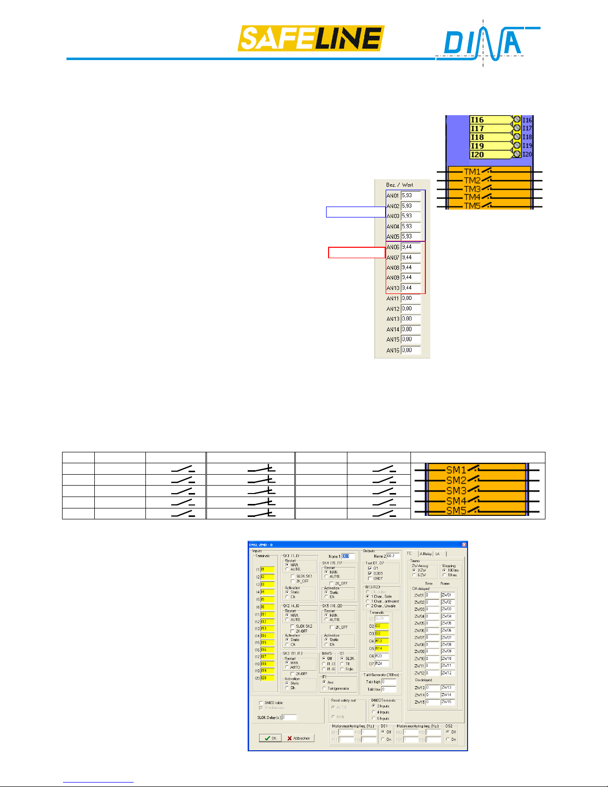
DNSL-ZMT: usage of inputs I16 to I20 for safety shutdown mats
For working with safety shutdown mats (max. 5) virtual redundant contacts TM1 to TM5 are provided. If the safety
shutdown mats is OK and not activated the corresponding
contacts TM1 to TM5 are closed. Stepping on the safety
shutdown mat or an internal malfunction of the mat will open
the corresponding contact. Contact closes again if no one is
on the mat.
A manual reset must be programmed using the logic module
in the DESIGNER.
The status of TM1 to TM5 may be monitored using the
Profibus.
The values for the analogue edges will be set using:
AN01 to AN05 for lower level
AN06 to AN10 for upper level
AN01/ AN06, AN02/ AN07, AN03/ AN08, AN04/ AN09 and
AN05/ AN10 are paired values.
Note for initial start-up:
At the clamp the measured voltage against 0V is 8,5V with a
free mat.
Additional parameters are not necessary.
Unused clamps I16-I20 may be left unconnected.
Note: Digital inputs and analogue safety mat inputs will be
processed in two channel mode and tested for plausibility on
the Central – and all Function modules. There is no single
channel processing.
SAFELINE DESIGNER
Parameter mask
Programming mask
The tension values
shown in the left picture
are for a safety mat with
shorting outputs using an
external 8,2Kohm Reference resistor.
For different reference
resistor values, contact
DINA Elektronik.
DNSL-ZMT: usage of inputs I16 to I20 for current source monitoring (4 to 20mA)
This inputs can be used to monitor the current value with an internal resistance of 500Ohm. The switching thresholds can be defined as for shutdown mats. Lower value and upper value must be entered. The interpretation will be
done via the virtual contacts SM1 to SM5. It may be to control outputs with right connection of the contacts. The left
connection can be linked with virtual +24V or with another software elements.
0V potential of the current source has to be connected with A2 of the central module.
Interrelationship between hardware inputs, voltage respectively current values and virtual contacts
Input min. value < min. value > min.,< max. value max. value > max. value Virtual contacts
I16 AN01 SM1 SM1 AN06 SM1
I17 AN02 SM2 SM2 AN07 SM2
I18 AN03 SM3 SM3 AN08 SM3
I19 AN04 SM4 SM4 AN09 SM4
I20 AN05 SM5 SM5 AN10 SM5
Parameter mask DNSL-ZMB
Description of the parameter mask: See
page 8 and 9.
The terminals O4-O5 and O6-O7
are two redundant NO contacts
Lower value
Upper value
 Loading...