

DINA DNSL-ZMB, DNSL-ZMT, DNSL-ZMK, DNSL-ZMA, DNSL-DS Original Instruction Manual
...
Original Betriebsanleitung
Original Instruction Manual
Wir sind Sicherheit.
We are Safety
Der direkte Weg zur sicheren Automation
The direct way to safe automation
20.05.2016 3
von 28 2016-05-20 3 of 28
Inhaltsverzeichnis Contents Seite
Konformitätserklärung Declaration of Conformity 4
Zertifizierungsdaten Certificate data 4
Produktbeschreibung Product description 5
Mounting Mounting 6
Zentralmodule Central modules 7
Feldbus Field bus 9
CANopen Feldbus mit Daten Transfer Interface CANopen field bus with data transfer interface 9
Profibus DP Feldbus mit Daten Transfer Interface Profibus DP field bus with data transfer interface 9
EtherCAT Feldbus mit Daten Transfer Interface EtherCAT field bus with data transfer interface 9
Daten Transfer Interface Data transfer interface 10
Drehzahlüberwachung Speed monitoring 11
Ein-, Ausgangsmodule In-, output modules 12
Netzwerkmodul Network module 13
Kaskadenmodul Cascade module 14
Sichere digitale und analoge Eingänge Safe digital and analogue inputs 15
Schaltmattenfunktionen über I16 – I20 an ZMT Shutdown mats function via I16 – I20 at ZMT 15
Zwei-Hand Funktion nach EN 574: Type IIIC Two-hand function according to EN 574, Type IIIC IC 15
Original Betriebsanleitung Original Instruction Manual
Page
Betriebsartenwahlschalter (BAWS) am Zentralmodul Mode selector switch (FMSS) at the central module 15
Sicherheitskreise mit manueller Quittierung (SK) Safety circuit with manual quit (SC) 15
Sicherheitskreise (SK) ohne Quit Safety circuit (SC) without quit) 16
Quit bei Sicherheitskreisen (SK) Quit for safety circuits (SC) 16
Drehzahlüberwachung am Zentralmodul ZMB, ZMR, ZMT Speed monitoring at central module ZMB, ZMR, ZMT 17
DNSL-DS: Drehzahlüberwachung, inkrementelles
Messsystem
Messsystem Anforderung Measuring system requirements 17
DNSL-DS: 2 Sensoren Messsystem DNSL-DS: 2 sensors measuring system 17
DNSL-DR: Drehzahlüberwachung Resolver Messsystem DNSL-DR: Speed monitoring, resolver measuring system 17
DNSL-SI: Drehzahlüberwachung, SSI Interface
Messsystem
Symbolfunktionen Function of symbols 18
Quittierung der Drehzahlüberwachung Quit of the speed monitoring 18
Bremsüberwachung bei DSV, DRV, SIV Brake monitoring with DSV, DRV, SIV 18
Richtungsüberwachung bei DNSL-DSV, DRV und SIV Direction monitoring with DNSL-DSV, DRV and SIV 18
DNCO Funktion zur Überwachung der
Umfangsgeschwindigkeit
Analoge Eingänge für DNCO-Funktion am DNSL-ZMA Analogue inputs for DNCO-function at DNSL-ZMA 19
Virtuelle Ein- und Ausgänge am Feldbus Virtual in- and outputs at fieldbus 19
Kabeladapter DNDA Cable adapter DNDA 19
Ausgänge von SAFELINE und ihre Verwendung Outputs of SAFELINE and its usage 20
Maßbilder und Rack Varianten und Einbau Dimension and rack variants an installation 21
Allgemeine technische Daten General technical data 21/ 23
Lebensdauer der Kontaktausgänge Electrical life of the contact outputs 24
Zertifikat Certificate 25/ 26
DNSL-DS Speed monitoring, incremental measuring
system
DNSL-SI: Speed monitoring, SSI interface measuring
system
DNCO function to monitor the peripheral speed 19
17
18
20.05.2016 4
von 28 2016-05-20 4 of 28
nach der Maschinenrichtlinie 2006/42/EG Anhang II 1A
According to the machinery directive 2006/42/EC attachment II 1A
Zentralmodule
Drehzahlüberwachung
Ein-, Ausgangsmodule
Relaismodule
Feldbusse
Netzwerkmodul
Central modules
Speed monitoring
In-
, output modules
Relay modules
Field busses
Network module
DNSL
-DS
DNSL
-IN
DNSL
-RM
230
DNSL
-CO
DNSL
-
NIV
Intended purpose:
Wolfschlugen, den
22.03
.2016
Wolfschlugen,
2
2.03.2016,
1ZD7
Zertifizier
t:
Original Betriebsanleitung Original Instruction Manual
Konformitätserklärung Declaration of Conformity
Laut Anhang I. 1. 5. 1 der Maschinenrichtlinie werden die
Schutzziele der Niederspannungsrichtlinie erfüllt.
Hersteller: DINA Elektronik GmbH, Esslinger Str. 84
D-72649 Wolfschlugen
Hiermit erklärt der Hersteller, dass das Produkt SAFELINE
mit folgenden Modultypen konform ist mit den
Bestimmungen der oben angegebenen Richtlinie.
DNSL-ZM
DNSL-ZMA
DNSL-ZMB
DNSL-DR
DNSL-IO
DNSL-IO2
DNSL-ZMK
DNSL-ZMR
DNSL-ZMT
Bestimmungsgemäße Verwendung:
Prüfgrundlage:
• EN 55011: 2009+A1 2010 (Klasse B),
EN 55011: 2009+A1 2010 (Klasse B),
EN 55011: 2009+A1 2010 (Klasse B), EN 55011: 2009+A1 2010 (Klasse B),
EN 61326
EN 61326----3333----1: 2008 SIL3, EN 61000
EN 61326EN 61326
EN 62061: 2005, EN 61326
EN 62061: 2005, EN 61326----3333----1: 2008
EN 62061: 2005, EN 61326EN 62061: 2005, EN 61326
• DIN EN 60947-5-1 (2010-4):
Niederspannungsschaltgeräte-Teil 5-1: Steuergeräte und
Schaltelemente; Elektromechanische Steuergeräte
• DIN EN 62061 (2005-12) :
Funktionale Sicherheit sicherheitsbezogener elektrischer,
elektromechanischer und programmierbarer elektronischer
Steuerungssysteme (SIL CL 3, ET 11071)
• DIN EN ISO 13849-1 (2008-12):
Sicherheitsbezogene Teile von Steuerungen-Teil 1: Allgemeine Gestaltungsleitsätze (Kategorie 4 ET 11071)
• DIN EN 574 III C (2008-12): Zweihandschaltungen
• GS-ET-20 (2009-1):
Zusatzanforderungen für die Prüfung und Zertifizierung
von Sicherheitsschaltgeräten
1: 2008 SIL3, EN 61000----6666----2: 2006
1: 2008 SIL3, EN 610001: 2008 SIL3, EN 61000
1: 2008
1: 20081: 2008
2: 2006----05,
2: 20062: 2006
05,
05, 05,
The protection target of the low voltage directive will be fulfilled
according to attachment I. 1. 5. 1 of the machinery directive.
Producer: DINA Elektronik GmbH, Esslinger Str. 84
D-72649 Wolfschlugen
The producer declares the product SAFELINE with the module
types as follows conforms to the regulations of the directives stated above.
DNSL-KM
DNSL-DP
DNSL-EC etc
Testing based on:
• EN 55011: 2009+A1 2010 (
EN 55011: 2009+A1 2010 (class
EN 55011: 2009+A1 2010 (EN 55011: 2009+A1 2010 (
EN 61326
EN 61326----1: 2006
EN 61326EN 61326
EN 62061: 2005, EN 61326
EN 62061: 2005, EN 61326----3333----1: 2008
EN 62061: 2005, EN 61326EN 62061: 2005, EN 61326
1: 2006----05 SIL3, EN 61000
1: 20061: 2006
05 SIL3, EN 61000----6666----2: 2006
05 SIL3, EN 6100005 SIL3, EN 61000
class B),
B),
classclass
B), B),
1: 2008
1: 20081: 2008
2: 2006----05,
2: 20062: 2006
05,
05, 05,
• DIN EN 60947-5-1 (2010-4):
Low-voltage switch gear and control gear; part 5.1: Control
circuit devises and switching elements - electromechanical
control circuit devices
• DIN EN 62061 (2005-12):
Functional safety of safety-related electrical, electronic and
programmable electronic control systems
(SIL CL 3, ET 11071)
• DIN EN ISO 13849-1 (2008-12)
Safety-related parts of control systems; Part 1: General principles for design (category 4 ET 11071)
• DIN EN 574 (2008-12): two-hand control devices
• GS-ET-20 (2009-1):
Basic principles for testing and certification of safety switch
devices
gezeichnet: Dirar Najib Geschäftsführer
Esslinger Str. 84, D 72649 Wolfschlugen.
Bevollmächtigter für die Zusammenstellung der technischen
Unterlagen
Gerät ist nicht zugelassen als Sicherheitsgerät
nach UL 508
Device is not evaluated as safety device under
UL 508
Zertifizierungsdaten Certificate data
DI
ELEKTRONIK
US LISTED
R
IND.CONT.EQ
File E227037
DIN EN 62061: SIL CL 3
DIN EN ISO 13849-1: .
Kategorie 4, PLe
MTTFD: 75 Jahre
DC
PFHD: 6,24x10
CCF: 85 Punkte,
DIN EN 62061
CCF: 95 Punkte,
TM: 20 Jahre
• durch den Fachausschuss für Elektrotechnik, Prüf- und Zer-
tifizierungsstelle Köln, Europäisch notifizierte Stelle
Kenn-Nummer 0340, EG Baumusterprüfungsbescheinigung
(BG-Nr.: ET 11070 vom 05.08.2011)
• EMV-Richtlinie bescheinigt durch ELMAC GmbH Bondorf,
Reg. Nr.: DAT-P-206/05-00
• QM System zertifiziert nach DIN EN ISO 9001:2000 durch
DQS, Frankfurt, Reg.-Nr.:67542-01
Signed by Dirar Najib General Manager
Esslinger Str. 84, D 72649 Wolfschlugen,
Authorized person for the combination of the technical
documents
DIN EN 62061: SIL CL 3
DIN EN ISO 13849-1:
Category 4, PLe
MTTFD: 75 years
: ≥ 90%
awg
-8
DC
: ≥ 90%
awg
PFHD: 6,24x10
-8
CCF: 85 points,
DIN EN 62061
CCF: 95 points,
TM: 20 years
Certificated by
• Fachausschuss für Elektrotechnik, Prüf- und
Zertifizierungsstelle Köln,
European notified institution, Identification-number 0340
EC-Type Test certificate (ET 11070 from 05-08-2011)
• EMC-directive certificated by “ELMAC GmbH Bondorf”,
Reg. No.: DAT-P-206/05-00
• QM System certificated according to DIN EN ISO 9001:2008
by “DQS, Frankfurt”, Reg.-No.: 67542 QM08

20.05.2016 5
von 28 2016-05-20 5 of 28
gefährlicher Spannung. Keine Schutzabdeckungen entfernen.
The unit must be disposed of properly when it reaches the end
Das beschriebene Produkt wurde entwickelt, um als Teil eines
einheiten sowie Konzepte für sichere Abschaltungen gebildet.
proving the effectiveness of the safety
Original Betriebsanleitung Original Instruction Manual
Sicherheitsbestimmungen Safety regulations
• Das Gerät darf nur von einer Elektrofachkraft oder unterwie-
senen Personen installiert und in Betrieb genommen werden,
die mit dieser Betriebsanleitung und den geltenden Vorschriften über Arbeitssicherheit und Unfallverhütung vertraut sind.
• Beachten Sie die VDE, EN sowie die örtlichen Vorschriften,
insbesondere hinsichtlich der Schutzmaßnahmen.
• Werden die Vorschriften nicht beachtet, kann Tod, schwere
Körperverletzungen oder hoher Sachschaden die Folge sein.
• Bei Not-Halt Anwendungen muss entweder die integrierte
Funktion für Wiedereinschaltsperre verwendet werden oder
der automatische Wiederanlauf der Maschine durch eine
übergeordnete Steuerung verhindert werden.
• Halten Sie beim Transport, Lagerung und im Betrieb die
Bedingungen nach EN 60068-2-1, 2-2 ein!
• Durch eigenmächtige Umbauten erlischt jegliche Gewährleis-
tung. Es können dadurch Gefahren entstehen, die zu
schweren Verletzungen oder sogar zum Tod führen.
• Montieren Sie das Gerät in einem Schaltschrank mit einer
Mindestschutzart von IP54! Staub und Feuchtigkeit können
sonst zu Beeinträchtigungen der Funktionen führen.
Der Einbau in einem Schaltschrank ist zwingend.
• Sorgen Sie für ausreichende Schutzbeschaltung an Aus-
gangskontakten bei kapazitiven und induktiven Lasten!
• Das Gerät ist einzubauen unter Berücksichtigung der nach
DIN EN 50274, VDE 0660-514 geforderten Abstände.
• Während des Betriebes stehen Schaltgeräte unter
• Wechseln Sie das Gerät nach dem ersten Fehlerfall aus!
• Entsorgen Sie das Gerät sachgerecht nach Ablauf der
Lebensdauer
• Bei Nichteinhaltung dieser Bestimmungen oder unsachge-
mäßer Anwendung übernimmt DINA Elektronik GmbH keinerlei Haftung für daraus entstehende Sach- und Personenschäden.
• Bewahren Sie diese Produktinformation auf!
Wichtiger Hinweis und Validierung
•
Gesamtsystems sicherheitsgerichtete Funktionen zu
übernehmen.
• Das Gesamtsystem wird durch Sensoren, Auswerte- Melde-
• Es liegt im Verantwortungsbereich des Anlageherstellers
einer Anlage die korrekte Gesamtfunktion sicherzustellen.
• Der Hersteller der Anlage/Maschine ist verpflichtet, die
Wirksamkeit des implementierten Sicherheitskonzepts
innerhalb des Gesamtsystems zu prüfen und nachweisen.
• Dieser Nachweis ist nach jeglicher Modifikation am
Sicherheitskonzept bzw. Sicherheitsparametern erneut zu
erbringen.
• Fa. DINA Elektronik GmbH ist nicht in der Lage, alle
Eigenschaften eines Gesamtsystems, das nicht durch DINA
Elektronik GmbH konzipiert wurde, zu garantieren.
• DINA Elektronik GmbH übernimmt auch keine Haftung für
Empfehlungen, die durch die nachfolgende Beschreibung
gegeben bzw. impliziert werden.
• Auf Grund der nachfolgenden Beschreibung können keine
neuen, über die allgemeinen Lieferbedingungen der Dina
Elektronik GmbH hinausgehenden Garantie-, Gewährleistungs- oder Haftungsansprüche abgeleitet werden.
•
Zur Vermeidung von EMV-Störgrößen müssen die
physikalischen Umgebungs- und Betriebsbedingungen am
Einbauort des Produkts dem Abschnitt EMV der
DIN EN 60204-1 entsprechen.
• The unit may only be installed and operated by those who are
qualified electrical engineers or have received sufficient training and are familiar with both these instructions and the current regulations for safety at work and accident prevention.
• Follow VDE, EN as well as local regulations especially as re-
gards preventative measures!
• Ignoring the safety regulations can lead to death, serious inju-
ry or cause considerable damage!
• In emergency stop applications use the internal function
“Speed output restart disable” or a higher level control unit
must ensure that the machine cannot start up again
automatically!
• Transport, storage and operating conditions should all
conform to EN 60068-2-1, 2-2. See technical details
• Any guarantee is void following unauthorised modifications.
This can lead to death, serious injury or cause considerable
damage!
• The unit should be mounted in a cabinet with a protection
class of IP54. Otherwise dampness and dust could lead to
functional impairment. The installation in a control cabinet is
imperative.
• Adequate fuse protection must be provided on all output con-
tacts especially with capacitive and inductive loads.
• The unit must be installed following the specification of DIN
EN 50274, VDE 0660-514 regarding the required distances.
• During operation, parts of the electronic switchgear carry
high voltage. The protective covers must not be removed.
• The device must be replaced after the first malfunction!
•
of it service life.
• In case of disregarding the safety regulations or improper use
DINA Elektronik GmbH shall not be liable for any damages to
persons and property.
• Keep the operating instructions!
Important notes and validation
• The described product has been developed as a part of a safe-
ty system.
• The system includes sensors, evaluation units, control units
and a concept for safe switch-off.
• The manufacturer is in charge to ensure the correct function-
ality of the entire system.
• The manufacturer is in charge to check and to prove the ef-
fectiveness of the safety concept.
• Any modification at the safety parameters or the safety con-
cept itself requires a reconcept.
• DINA Elektronik GmbH cannot guarantee properties of sys-
tems that not have been established in their own
responsibility.
• DINA Elektronik GmbH also does not accept liability for any
recommendations derived from the following description.
• Claims that go beyond the rights cited in the warranty are
excluded.
•
To avoid EMC disturbances the physical environmental and
functional requirements at the installation place have to be in
accordance with chapter EMC of DIN EN 60204-1.

20.05.2016 6
von 28 2016-05-20 6 of 28
Original Betriebsanleitung Original Instruction Manual
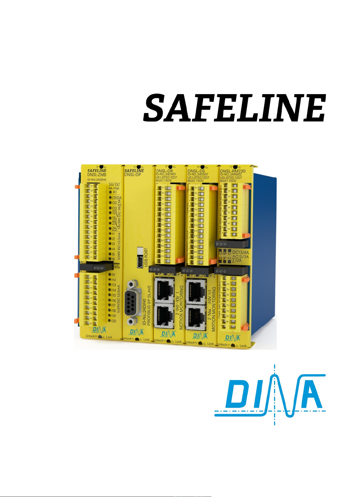
Produktbeschreibung
• SAFELINE ist konzipiert zum Einsatz an Maschinen
und Anlagen zum Schutz der Bediener gegen
potentielle Gefahren und Anlagen gegen Zerstörung.
• Das Produkt ist in einem Metallgehäuse eingebaut
und kann an einer Normschiene befestigt werden.
• Die einzelnen Module sind steckbar.
• Die Anzahl der eingesetzten Module bestimmt die
Breite des Racks.
• Bis zu 15 Module sind möglich. Racks für 2, 3, 5, 7, 9, 11,
13 und 15 Module sind lieferbar.
• Nicht bestückte Plätze werden mit einem neutralen
Deckel belegt. (ID-No.: 10BD00)
• Alle Module sind über ein redundantes Bussystem
intern miteinander verbunden.
• Zur Erfüllung der Anforderungen von breiten
Einsatzbereichen sind verschiedene Module mit den
verschiedensten Funktionen lieferbar.
• SAFELINE ist mit diversen Feldbus Modulen lieferbar.
• Diverse sichere Funktionen sind verfügbar wie
Logikbausteine, Zeitwerke, Sicherheitskreise,
Betriebsartenwahlschalter, Generator, Zähler,
Vergleicher, Starter, Rückführung,
Wiedereinschaltsperre usw.
• Eine Vielzahl von sicheren digitalen und analogen
Eingängen, sicheren Halbleiter- sowie sicheren
Kontaktausgängen ist Verfügbar.
• Alle Halbleiterausgänge sind überlast- und
kurzschlusssicher.
• Der Status der Eingänge, Ausgänge und Betriebs-
spannung wird über LED angezeigt.
• Siehe auch SAFELINE Anzeige.
• Die Betriebsspannung (24V DC) für alle Module wird
über die Klemmen A1/ A2 am Zentralmodul
angeschlossen.
• Zur Versorgung der Halbleiterausgänge an den
Funktionsmodulen mit 24V DC ist die Klemme P
vorgesehen.
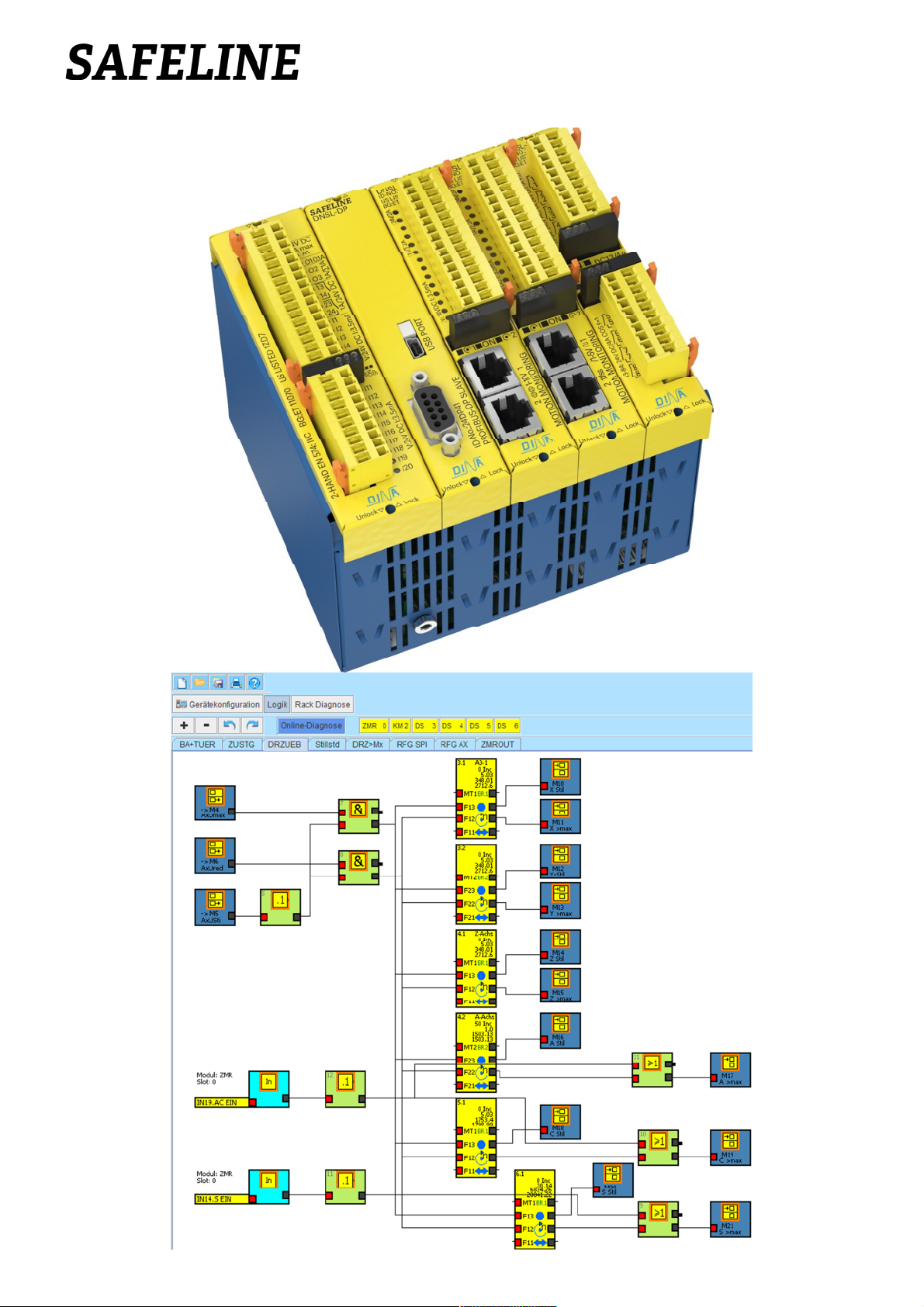
• Die Anwenderapplikation wird mit dem SAFELINE
Designer am PC erstellt und über die USB bzw. COM
Interface am Zentralmodul übertragen.
• Der Designer ist eine von DINA entwickelte Software.
• Bei Zentralmodul mit USB Interface kann die
Anwender Applikation sowie Designer,
Betriebsanleitungen usw. auf einem internen Speichermedium hinterlegt werden.
• Das Medium ist zu verwenden wie ein Laufwerk.
• Das zu verwendende Anschlusskabel bei COM PORT
ist V24 (1:1). Von Bedeutung sind nur Pin 2, 3 und 5.
Verhalten bei Störung:
• Ausgang O1 am Zentralmodul schaltet ab.
• Abhilfe: Kontrolle der Verdrahtung und Konfiguration.
• Unterbrechung der Betriebsspannung löscht den Fehler.
• Siehe auch Diagnose Tool am Designer.
Product description
• SAFELINE is appropriated to be used in machines
and plants to protect the operator against potential
dangers and plants against destruction.
• SAFELINE is housed in a metal rack. It can be
mounted by spring fasteners to a DIN rail.
• The individual modules are pluggable.
• The equipment is available in different housing sizes
depending on the number of the modules used.
• Up to 15 modules can be used. Racks with 2, 3, 5, 7, 9,
13 and 15 slots are available.
• Unused slots are closed with a blind cover. ID-No.:
10BD00
• All modules are connected by the redundant back-
plane bus system.
• To fulfil the requirements of the wide ranges of needs
different modules with diverse functions are
available.
• SAFELINE is deliverable with divers field bus mod-
ules.
• A variety of safe functions are available such as logic
modules, timers, safety circuits, mode selector,
generator, counters, comparators, feedback, restart
interlock etc.
• A lot of safe digital and analogue inputs, safe
semi-conductor outputs and contact outputs are
available.
• All semi-conductor outputs are overload and short
circuit proofed.
• The switching status of all I/O terminals and supply
voltage are indicated by LED.
• See also SAFELINE display.
• The power supply (24V DC) is connected to the
terminals A1/ A2 at the central module for all
modules.
• To supply the semi-conductor outputs at the
function modules with 24V DC the terminal P is
designated.
• The user application is configurable with the SAFE-
LINE Designer on a PC. The application is transferred
by the USB or COM interface at the central module.
• The Designer is software developed by DINA.
• The user application, instruction manual, Designer
and all other documents can be stored on a memory
medium, if a central module with an USB interface is
used.
• The Medium is to use as a drive.
• The used connection cable with COM PORT interface
is V24 (1:1). Pins 2, 3 and 5 are only important.
Behavior with errors:
• Output O1 at the central module is switching off.
• Correction Inspection of the wiring and assembly
• Switching off and on of the power clears the errors.
• See also diagnostics tool at the Designer.
20.05.2016 7
von 28 2016-05-20 7 of 28
Original Betriebsanleitung Original Instruction Manual
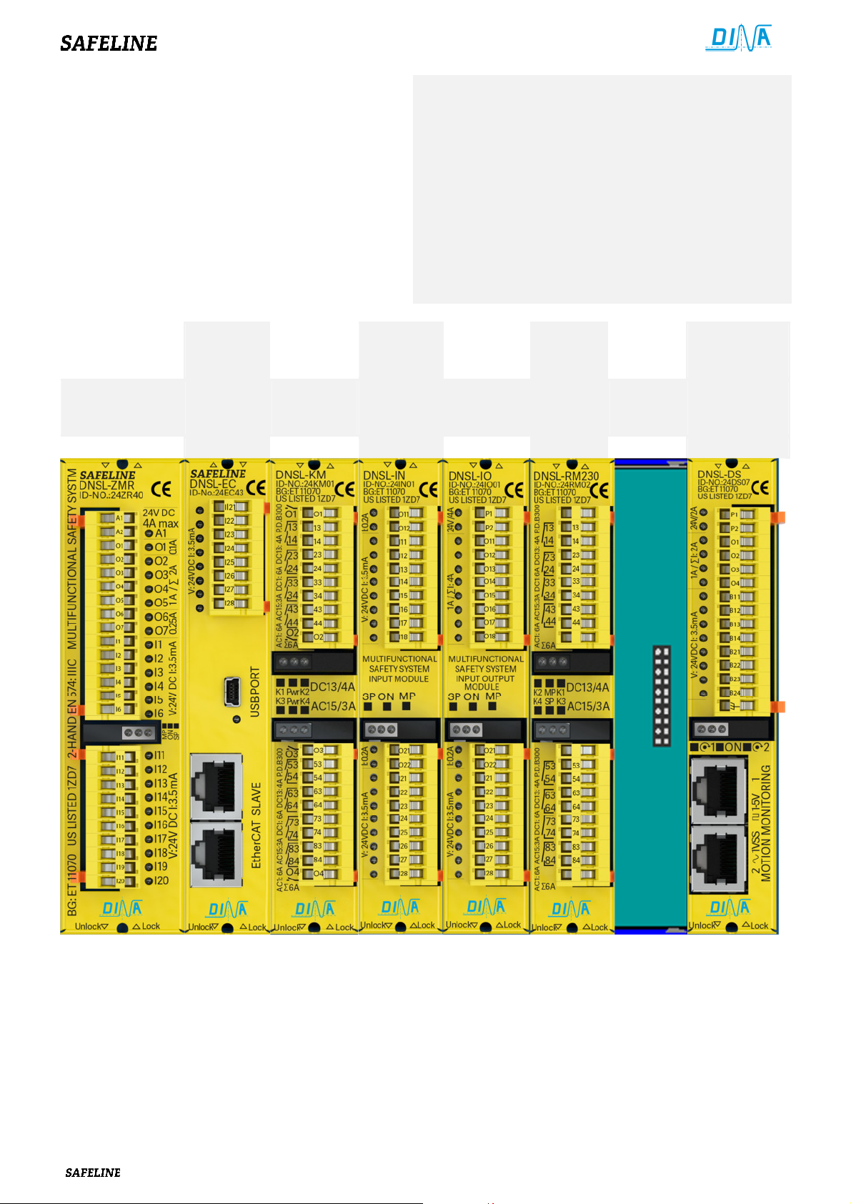
Aufbau
• Ein Zentralmodul ist in einer Applikation notwendig.
• Die Anzahl anderer Module ist bedarfsabhängig.
• Das Zentralmodul ist immer links im Rack.
• Der Feldbus ist im zweiten Steckplatz.
• Bei Verwendung von ZMB, ZMT oder ZMR ist der
Daten Interface rechts separat montiert.
• Bei Feldbus Einsatz ist Feldbus und Daten Interface
im selben Module integriert.
• Das Relaismodul DNSL-KM ist nur mit DNSL-ZMR
einsetzbar und ist direkt rechts davon zu stecken.
• Der Steckplatz für alle anderen Module ist beliebig.
• A central module is necessary in an Application.
• The number of other modules is breath-responsive.
• The central module is always left in the rack.
• The field bus is in the next slot.
• The data interface is separately right mounted if ZMB,
ZMT or ZMR are used.
• The data interface and the field bus are integrated at
the same module if a field bus is used.
• The relay module DNSL-KM can be used only with the
DNSL-ZMR and must be placed at the right side.
• All other modules may be placed in any order.
Zentralmodul
Central module
Feldbus
Daten
Interface
Field bus
Data
interface
Relais
Modul
Relay
module
Ein-,
Ausgang
Modul
In-,
output
module
Ein-,
Ausgang
Modul
In-,
output
module
DNSL-ZMR DNSL-EC DBSL-KM DNSL-IN DNSL-IO DNSL-RM
Mounting
Relais
Modul
Relay
module
Frei
Free
Drehzahl-
überwachung
Modul
Speed
monitoring
Modul
DNSL-DS
20.05.2016 8
von 28 2016-05-20 8 of 28
V24
USB
Zentralmodule
Central modules
DNSL
-
O1
Ausgang, System OK
Betriebsspannung 24V DC für alle Module in
output, system OK
O2-O5
sichere Halbleiterausgänge
safe semi
-
conductor outputs
U
R,UA,
0V
Anschluss für Potentiometer
Connection for Potentiometer
O2, O3
2 sichere
Halbleiterausgänge
safe semi
-
conductor outputs
1:
I11/I12
2 sichere Drehzahlüberwachungen
2
safe
speed monitoring
1:
I11/I12
2 sichere Drehzahlüberwachungen
2 safe speed monitoring
1:
I11/I12
2
sichere Drehzahlüberwachungen
2 safe speed monitoring
•
Unterbrechung der Betriebsspannung löscht den Fehler.
•
Switching off and on of the power clears the errors.
Ein-, Ausgänge und Spannung
In-/ outputs and Pwr
Pwr
4
73/74, 83/84 Ein
-
AUS
73/74, 83/84 ON
-
OFF
Module
Module
ModuleModule
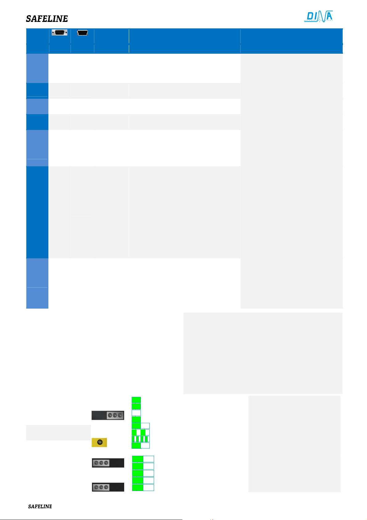
Original Betriebsanleitung Original Instruction Manual
Klemme
ID-No: ID-No: Terminal Beschreibung Description
alle
alle al
ZM
ZM 24ZM20 24ZM30
ZMZM
ZMA
ZMA 24ZA20 24ZA30
ZMAZMA
ZMK
ZMK 24ZK20 24ZK30
ZMKZMK
ZMB
ZMB
ZMBZMB
CP
CP
CPCP
UP
UP
UPUP
ZMR
ZMR
ZMRZMR
CP
CP
CPCP
UP
UP
UPUP
KM
KM
KMKM
allealle
24ZB40
24CP40
24UP41
24ZR40
24CP40
24UP41
24KM01
alllll
alal
A1/ A2
I1-I6
O6, O7
O2, O3
13-14/23-24
2: I13/I14
I11-I20
O2, O3
13-14/23-24
2: I13/I14
I11-I20
O2-O5
O6, O7
O1-O4
13/14, 23/24
33/34, 43/44
53/54, 63/64
73/74, 83/84
der Applikation
sichere Eingänge für Sicherheitsfunktionen
1 sicherer oder 2 Takt Ausgänge
sichere Halbleiterausgänge
Kontaktausgang, 2 sichere NO Kontakte
Sensor mit 24V Signalen
sichere Eingänge für Sicherheitsfunktionen
sichere Halbleiterausgänge
Kontaktausgang, 2 sichere NO Kontakte
Sensor mit 24V Signalen
sichere Eingänge für Sicherheitsfunktionen
sichere Halbleiterausgänge
Schalt- oder Taktausgänge
Ausgangserweiterung nur in Verbindung
mit DNSL-ZMR
Diagnose Kontaktausgänge
Sichere Kontaktausgänge
Power supply 24V DC for all
modules in the application
safe inputs for safety functions
1 safe or 2 clock outputs
safe semi-conductor outputs
contact output, 2 safe NO contacts
Sensor with 24V signals
safe inputs for safety functions
safe semi-conductor outputs
contact output, 2 safe NO contacts
Sensor with 24V signals
safe inputs for safety functions
safe semi-conductor outputs
switching or clock outputs
Output extension, possible with
DNSL-ZMR only
Diagnostics contact outputs
Safe contact outputs
ZMT
ZMT
ZMTZMT
Das Interface USB bzw. V24 ist für Datentransfer zwischen
• Bei USB-Versionen können Daten wie Applikation, Designer
• Bei Einsatz von DNSL-ZMB, ZMR oder ZMT befindet sich
Verhalten bei Störung
Verhalten bei Störung:
Verhalten bei StörungVerhalten bei Störung
• Ausgang O1 am Zentralmodul schaltet ab.
• Abhilfe: Kontrolle der Verdrahtung und Konfiguration.
•
24ZT40
CP
CP
24CP40
CPCP
UP
UP
UPUP
SAFELINE und einem PC sowie Diagnoseaufgaben.
auf einem internen Speichermedium hinterlegt werden.
Das Medium arbeitet als Laufwerk.
das Interface auf einem separaten Modul. Es kann auch am
eingesetzten Feldbus integriert sein.
24UP41
Zentralmodule
Anzeige
Central modules
Display
DNSL-KM
Anzeige / Display
2: I13/I14
I11-I15
I16-I20
O2, O3
13-14/23-24
2 1 3
2 Pwr 1
4 Pwr 3
Sensor mit 24V Signalen
sichere Eingänge für Sicherheitsfunktionen
sichere Eingänge für Schaltmattenfunktion
Fa. Mayser Typ TS/W1 und TS/ BK1
2 sichere Halbleiterausgänge
Kontaktausgang, 2 sichere Kontakte
1
2
2
3
3 3
3
3
on
off
1
2
3
• Interne Spannung
• Master OK
• Daten Transfer
• Slave OK, Applikation validiert
• Applikation nicht validiert
• SLOK OFF
• Daten Transfer/ Diagnose
•
• Interne Spannung
• 13/14, 23/24 Ein-AUS
• 33/34, 43/44 Ein-AUS
• 53/54, 63/64 Ein-AUS
•
Sensor with 24V signals
safe inputs for safety functions
safe inputs for shut mat function
co. Mayser type TS/W1 und TS/ BK1
The interface USB respectively V24 is used to transfer data
between the PC and SAFELINE and for diagnostics duties.
• The user application and Designer can be stored on an
internal memory medium if the USB PORT is used.
The memory medium works as a drive.
• The interface is mounted at a separate module if DNSL-ZMB,
ZMR or ZMT is used. The interface can be also mounted at
the used field bus.
Behavior with errors
Behavior with errors:
Behavior with errorsBehavior with errors
• Output O1 at the central module is switching off.
• Correction Inspection of the wiring and assembly
•
safe semi-conductor outputs
contact output, 2 safe NO contacts
• Internal voltage
• Master OK
• Data transfer
• Slave OK, Application validated
• Application not validated
• SLOK OFF
• Data transfer/ Diagnostics
•
• Internal voltage
• 13/14, 23/24 ON-OFF
• 33/34, 43/44 ON-OFF
• 53/54, 63/64 ON-OFF
•
20.05.2016 9
von 28 2016-05-20 9 of 28
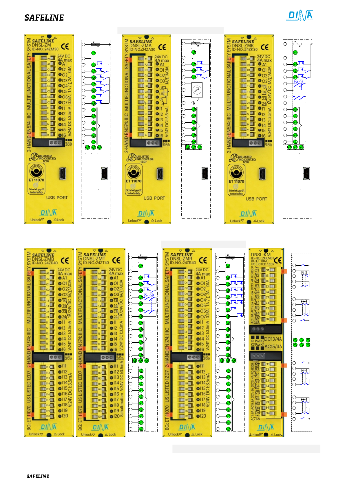
DNSL
DNSL----ZM Schematic
DNSLDNSL
ZM Schematic DNSL
ZM SchematicZM Schematic
Original Betriebsanleitung Original Instruction Manual
DNSL----ZMA Schematic
DNSLDNSL
ZMA Schematic
ZMA SchematicZMA Schematic
DNSL
DNSL----ZMK Schematic
DNSLDNSL
ZMK Schematic
ZMK SchematicZMK Schematic
A1
24V
DC
0V
A2
O1
O2
O3
O4
O5
O6
O7
I1
I2
I3
I4
I5
I6
MPON SP
ZM
6A
24V
Eingänge/ Inputs
USB
PORT
A1
24V
DC
0V
A2
O1
O2
O3
O4
O5
O6
O7
I1
I2
I3
I4
I5
I6
MPON SP
ZMA
6A
24V
Eingänge/ Inputs
USB
PORT
A1
24V
DC
0V
A2
O1
O2
O3
O4
O5
O6
O7
I1
I2
I3
I4
I5
I6
MPON SP
ZMK
6A
24V
Eingänge/ Inputs
USB
PORT
Zentralmodule mit separat aufgebautem Interface
Zentralmodule mit separat aufgebautem Interface Central modules with separately mounted interface
Zentralmodule mit separat aufgebautem InterfaceZentralmodule mit separat aufgebautem Interface
DNSL
DNSL----ZMB
DNSLDNSL
ZMB DNSL
ZMBZMB
DNSL----ZMT
DNSLDNSL
ZMT Schema
ZMTZMT
Schema DNSL
SchemaSchema
6A
A1
24V
DC
0V
A2
24V
O1
O2
O3
13
14
23
24
I1
I2
I3
I4
I5
I6
MPON SP
I11
Eingänge/ Inputs
I12
ZMB
I13
ZMT
I14
I15
I16
I17
I18
I19
I20
Eingänge/ Inputs
Central modules with separately mounted interface
Central modules with separately mounted interfaceCentral modules with separately mounted interface
DNSL----ZMR
DNSLDNSL
ZMR Schema
ZMRZMR
Schema DNSLKM
SchemaSchema
6A
A1
24V
DC
0V
A2
DNSLKM Schema
DNSLKMDNSLKM
24V
O1
O2
O3
13
14
23
24
I1
I2
I3
I4
I5
I6
MPON SP
I11
Eingänge/ Inputs
I12
ZMR
I13
I14
I15
I16
I17
I18
I19
I20
Eingänge/ Inputs
Schema
SchemaSchema
Ausgang 1
Output 1
24V
O1
13
14
K1
23
24
Ausgang 2
Output 2
33
34
K2
43
44
24V
O2
KM
Pwr
K1 K2
K3 K4
Pwr
Ausgang 3
Output 3
O3
24V
53
54
K3
63
64
73
74
K4
83
84
24V
O4
Ausgang 4
Output 4
Siehe Feldbus und Daten Transfer Interface Seite 9/ 10 See field bus and data transfer interface page 9/ 10
 Loading...