

DINA DNSL-ZMA, DNSL-ZMT, DNSL-ZMB, DNSL-ZMR, DNSL-DS Original Instruction Manual
...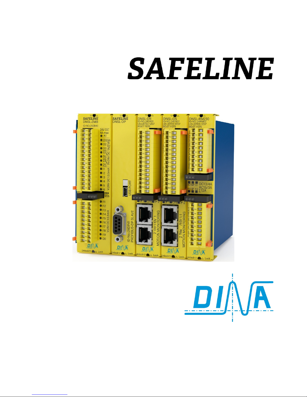
Original Instruction Manual
we are safety.

Original instruction manual Date: 2017.08.28 Page 2 of 28
Original instruction manual Date: 2017.08.28 Page 3 of 28
The direct way to safe automation

Inhaltsverzeichnis
1
SAFELINE Modules ........................................................................................................................................................................... 6
1.1 Intended purpose ............................................................................................................................................................................. 6
2
Safety regulations ............................................................................................................................................................................ 7
2.1 Important notes and validation ................................................................................................................................................... 7
3
Product description ......................................................................................................................................................................... 8
o
Behaviour with errors...................................................................................................................................................................... 8
4
Mounting ............................................................................................................................................................................................. 9
5
Central modules .............................................................................................................................................................................. 10
5.1 Schematic and display .................................................................................................................................................................. 10
5.2 Front view of the central modules ............................................................................................................................................ 11
6
Field busses and interfaces ......................................................................................................................................................... 11
7
Standstill and speed monitoring................................................................................................................................................ 12
7.1 Schematic, display and front view ............................................................................................................................................ 12
8
In-, output modules ........................................................................................................................................................................ 13
8.1 Schematic, display and front view ............................................................................................................................................ 13
9
Kaskadierung über DNSL-CI und DNSL-CM .......................................................................................................................... 14
10 Networking using DNSL-NI ......................................................................................................................................................... 15
11 Inputs for safety functions .......................................................................................................................................................... 16
11.1 Safe Shutdown mat functions using I16 – I20 at DNSL-ZMT ............................................................................................ 16
11.2 Input for function mode switch (FMSS) at the central module ....................................................................................... 16
11.3 Input for Tow-Hand functions according to EN 574: Type IIIC......................................................................................... 16
11.4 Eingänge für Sicherheitskreise (SK) mit manuellem Quitt ............................................................................................... 17
11.5 Inputs for safety circuit without quit input ............................................................................................................................ 17
11.6 Quit for safety circuits (SC) ......................................................................................................................................................... 18
12 Standstill and speed monitoring................................................................................................................................................ 18
12.1 Standstill and speed monitoring at DNSL-ZMB/ ZMR/ ZMT ............................................................................................ 18
12.2 Requirement at Proximity sensors ............................................................................................................................................ 18
12.3 Standstill and speed monitoring using DNSL-DS ................................................................................................................ 19
12.4 Requirement at the Measuring system ................................................................................................................................... 19
12.5 Standstill and speed monitoring using 2 Sensors for measuring system .................................................................... 19
12.6 Standstill and speed monitoring using DNSL-DR ................................................................................................................ 19
12.7 Standstill and speed monitoring using DNSL-SI ................................................................................................................. 20
12.8 Quit of the speed monitoring ..................................................................................................................................................... 20
12.9 Brake monitoring with DSV, DRV, SIV ..................................................................................................................................... 20
12.10 Direction monitoring with DNSL-DSV, DRV and SIV .......................................................................................................... 20
12.11 DNCO Function to monitor the Peripheral speed ............................................................................................................... 21
12.12 Analogue inputs for DNCO-function at DNSL-ZMA ........................................................................................................... 21
13 Cable adapter................................................................................................................................................................................... 21
14 Data in- and outputs at the field bus ....................................................................................................................................... 22
15 Outputs at SAFELINE ................................................................................................................................................................... 23
16 General technical data ................................................................................................................................................................ 24

Original instruction manual Date: 2017.08.28 Page 5 of 28
16.1 Electrical characteristics ............................................................................................................................................................ 24
16.2 Semiconductor outputs at the central module ................................................................................................................... 24
16.3 Semiconductor outputs at the function modules .............................................................................................................. 24
16.4 Contact outputs at at SAFELINE .............................................................................................................................................. 25
16.5 Electrical life of the contact outputs ...................................................................................................................................... 26
17 Dimension and installation .........................................................................................................................................................27
17.1 Rack variants ....................................................................................................................................................................................27
SAFELINE Modules
Original instruction manual Date: 2017.08.28 Page 6 of 28
1 SAFELINE Modules
Central module Speed monitoring In-, output modules Relay modules Field bus modules Network modules
DNSL-ZM
DNSL-ZMA
DNSL-ZMB
DNSL-ZMK
DNSL-ZMR
DNSL-ZMT
DNSL
-DS
DNSL-DR
DNSL-SI
DNSL-IN
DNSL-IO
DNSL-IO2
DNSL-RM
DNSL-KM
DNSL-RM
DNSL-KM
DNSL
-CO
DNSL-DP
DNSL-EC etc
DNSL-NI
1.1
Intended purpose
• Testing based on:
• EN 55011: 2009+A1 2010 (class B), EN 61326-1: 2006-05 SIL3, EN 61000-6-2: 2006-05,
EN 62061: 2005, EN 61326-3-1: 2008
• DIN EN 60947-5-1 (2010-4): Low-voltage switch gear and control gear;
part 5.1: Control circuit devises and switching elements - electromechanical control circuit devices
• EN ISO 13849-1 (2016-06): Safety-related parts of control systems;
Part 1: General principles for design (category 4, PL e, ET 16110 from 2016-08-012)
• DIN EN ISO 13849-2: Safety-related parts of control systems; Part 2: Validation
• DIN EN 574 (2008-12): two-hand control devices type III C using contact outputs type III A using
semi-conductor outputs
• GS-ET-20 (2014-10): Basic principles for testing and certification of safety switch devices
Authorized person for the combination of the technical documents: Dirar Najib, CEO,
Esslinger Str. 84, D 72649 Wolfschlugen
Wolfschlugen, 2016-08-15Zertifizierungsdaten
EN ISO 13849-1: Category 4, PLe
EN 574: two-hand function
MTTFD: 75 years
DC
awg
: ≥ 90%
PFHD: 6,24x10
-8
CCF: 85 points,
DIN EN 62061
CCF: 95 points,
TM: 20 years
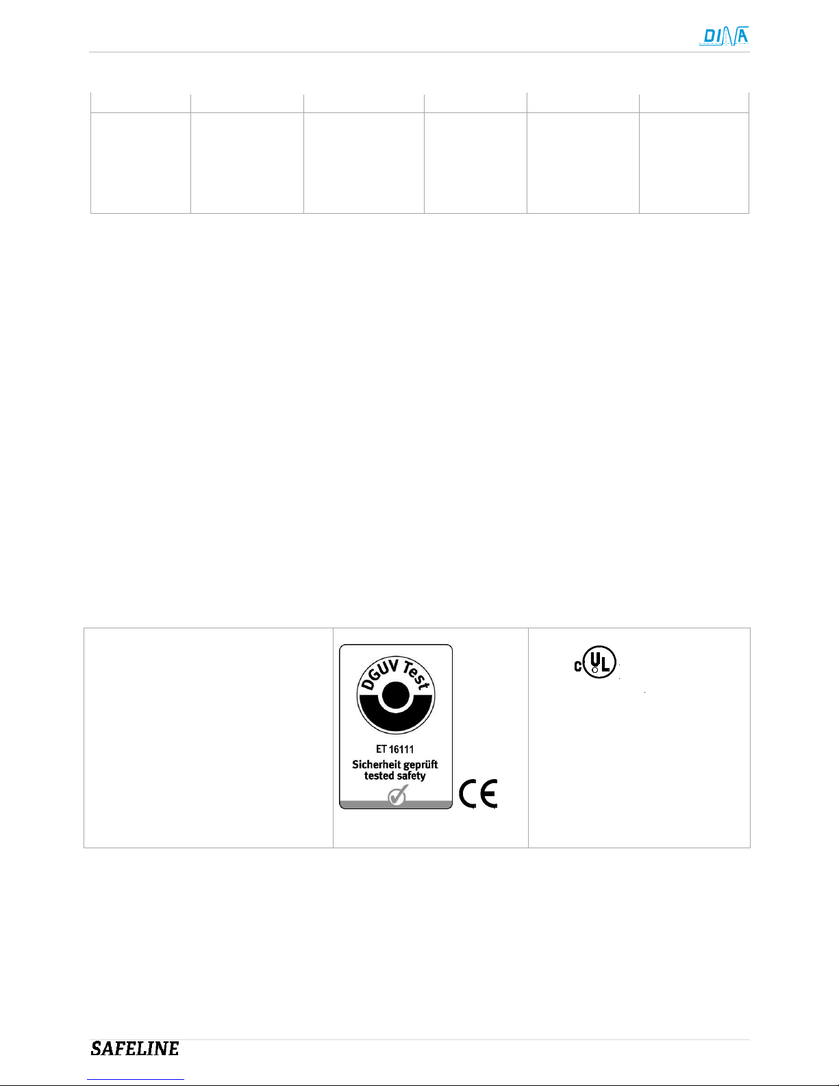
R
1ZD7
US LISTED
IND.CONT.EQ
File E227037
Certificated by: (Fachausschuss für Elektrotechnik, Prüf- und Zertifizierungsstelle Köln)
European notified institution, Identification-number 0340, EC-Type Test certificate (DGUV Test: ET 16110 from 12-08-2016)
EMC-directive certificated by “ELMAC GmbH Bondorf”, Reg. No.: DAT-P-206/05-00
CNL, USL: File E227037
QM System certificated according to DIN EN ISO 9001:2015 by “DQS, Frankfurt”, Reg.-No.: 67542 QM08
Certificate and declaration of conformity: See www.dina.de

Safety regulations
Original instruction manual Date: 2017.08.28 Page 7 of 28
2 Safety regulations
• The device may only be installed and commissioned by an electrician or trained persons who are familiar with
these operating instructions and the applicable regulations regarding work safety and accident prevention.
• Observe the VDE, EN and local regulations, particularly with respect to the protective measures.
• Failure to observe the regulations may result in death, severe bodily injury or extensive property damage.
• For emergency-stop applications, either the integrated function for restart interlock must be used or
automatic restarting of the machine must be prevented by means of a higher-level control.
• During transport, storage and operation adhere to the conditions specified in EN 60068-2-1, 2-2!
• Unauthorized modifications shall render any warranty null and void.
• Dangers may thereby arise that could result in severe injuries or even death.
• Install the device in a control cabinet with a protection class of at least IP54! Dust and moisture may
otherwise result in impaired functions.
• Installation in a control cabinet is mandatory.
• Ensure adequate protection circuits at output contacts for capacitive and inductive loads!
• The device is to be installed taking into account the distances required per DIN EN 50274, VDE 0660-514.
• During operation, switching devices carry dangerous voltage. Do not remove protective covers.
• Replace the device after the first malfunction!
• Properly dispose of the device at the end of its service life.
+
-
• If these regulations are not adhered to or in the event of improper use, DINA Elektronik GmbH accepts
absolutely no liability for the resulting property damages or personal injury.
• Save this product information!
2.1
Important notes and validation
• The product described here was developed to perform safety related functions as part of a complete system.
• The complete system consists of sensors, evaluation and message units as well as concepts for safe
shutdowns.
• It is the responsibility of the manufacturer of a system or machine to ensure the proper overall function.
• The manufacturer of the system is required to test and to document the effectiveness of the implemented
safety concept within the complete system.
• This verification is to be performed after every modification to the safety concept or to safety parameters.
• DINA Elektronik is not in the position to guarantee the properties a complete system that was not designed
by DINA.
• DINA Elektronik GmbH also accepts no liability for recommendations that are given or implied by the
following description.
• No new guarantee, warranty or liability claims that extend beyond DINA's general delivery conditions can be
derived on the basis of the following description.
• To avoid EMC disturbances, the physical environmental and operating conditions at the installation location
of the product must comply with section EMC of DIN EN 60204-1.
• The safety function must be required every month if there is performance level (e) and every year if there is
PLd is required by using contact outputs.
• The information in the general technical data at the end of the operating instructions must be adhered to.

Product description
Original instruction manual Date: 2017.08.28 Page 8 of 28
3 Product description
• SAFELINE is appropriated to be used in machines and plants to protect the operator against potential
dangers and plants against destruction.
• SAFELINE is housed in a metal rack. It can be mounted by spring fasteners to a DIN rail.
• The individual modules are pluggable. The number of the used modules set the rack width. Up to 15 modules
can be used.
• Racks with 2, 3, 5, 7, 9, 13 and 15 slots are available.
• Unused slots are closed with a blind cover. ID-No.: 10BD00
• All modules are connected by 2 backplane bus system.
• To fulfil the requirements of the wide ranges of needs different modules with diverse functions are available.
• SAFELINE is deliverable with different field bus modules.
• A variety of safe functions are available such as logic modules, timers, safety circuits, mode selector,
generator, counters, comparators, feedback, restart interlock etc.
• A lot of safe digital and analogue inputs, safe semi-conductor outputs and contact outputs are available.
• Semi-conductor outputs are overload and short circuit proofed.
• The switching status of all I/O terminals and supply voltage are indicated by LED.
• The power supply (24V DC) is connected to the terminals A1/ A2 at the central module for all modules.
• To supply the semi-conductor outputs at the function modules with 24V DC the terminal P is designated.
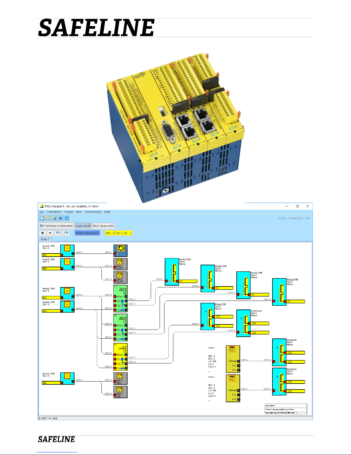
• The user application is configurable with the SAFELINE Designer on a PC. The application is transferred by
the USB or V24 interface at the central module. The Designer is software developed by DINA.
• The user application, instruction manual, Designer and all other documents can be stored on a memory
medium, if a central module with an USB interface is used.
• The Medium is to use as a drive.
• The used connection cable with COM PORT interface is V24 (1:1). Pins 2, 3 and 5 are only important.
• Remark
• The function devices are tested safe and certificated as a part of the firmware.
• A modification of the certified function devices as part of the firmware is excluded.
o Behaviour with errors
• Output O1 at the central module is switching off.
• Correction Inspection of the wiring and assembly
• Switching off and on of the power clears the errors. See also diagnostics tool at the Designer

Mounting
Original instruction manual Date: 2017.08.28 Page 9 of 28
4 Mounting
• A central module is necessary in an Application.
• The number of other modules is breath-responsive.
• The central module is always left in the rack.
• The field bus is in the next slot.
• The data interface is separately right mounted if ZMB, ZMT or ZMR are used.
• The data interface and the field bus are integrated at the same module if a field bus is used.
• The relay module DNSL-KM can be used only with the DNSL-ZMR and must be placed at the right side.
• All other modules may be placed in any order
DNSL
-
ZMR DNSL
-EC
DNSL
-KM
DNSL
-DR
DNSL
-IN
DNSL
-IO
DNSL
-
IO2 DNSL
-RM
Frei DNSL
-DS
 Loading...