

DINA DNDSmodular Original Instruction Manual
Metallgehäuse
Kunststoffgehäuse
Metal housing
Synthetically housing
Original Betriebsanleitung
Original Instruction Manual
Wir sind Sicherheit.
We are safety
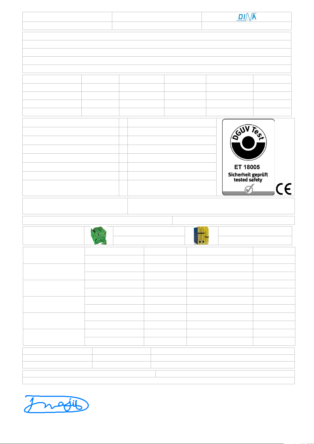
EU-Konformitätserklärung
EU declaration of conformity
Dichiarazione di conformità UE
Dichiarazione di conformità UE
Declaración UE de conformidad
Die nachfolgend aufgeführten Produkte sind konform mit den Anforderungen der folgenden Richtlinien
The beneath listed products are in conformity with the requirements of the following directives
Les produits mentionnés ci-dessous sont conformes aux exigences imposées par les directives suivantes
I prodotti sotto elencati sono conformi alle direttive sotto riportate
Los productos listados a continuación son conforme a los requisitos de las siguientes directivas
Maschinenrichtlinie
2006/42/EG
EMV Richtlinie
2014/30/EU
RoHS-Richtlinie
2011/65/EU
Machinery directive
2006/42/EC
EMC Directive
2014/30/EU
RoHS Directive
2011/65/EU
Directive Machines
2006/42/CE
Directive de CEM
2014/30/UE
Directive de RoHS
2011/65/UE
Direttiva Macchine
2006/42/CE
Direttiva EMV
2014/30/UE
Direttiva RoHS
2011/65/UE
Directiva de máquinas
2006/42/CE
Directiva CEM
2014/30/UE
Directiva RoHS
2011/65/UE
Folgende Normen sind angewandt:
a
• EN 55011: 2009+A1 2010 (class A)
Following standards are used:
b
• EN 61000-6-4: 2007 (class A)
Les normes suivantes sont appliquées:
c
• DIN EN 61000-6-2: 2005
Vengono applicate le seguenti norme:
d
• DIN EN 61326-3-1: 2008 (SIL 3)
Se utilizan los siguientes estándares:
e
• DIN EN 60947-5-1: 2015-05
f
• DIN EN ISO 13849-1: 2016-06
g
• DIN EN ISO 13849-2: 2013-02
Zusatzanforderung:
• DGUV Test: GS-ET-20: 2016-10
EG-Baumusterprüfbescheinigung: ET 18004/ Kategorie 4/ PLe
EC-Type Test certificate: ET 18004/ category 4/ PLe
Kunststoff Gehäuse
Metall Gehäuse
Synthetically housing
Metal housing
Produkt
Eingangsmodule
Produkt
Eingangsmodule
Product
Input modules
Product
Input modules
Bezeichnung
der Bauteile
DNDS 1M–DNDS 8M
DNDS 1E V6
DNDS 1EG V7
DNDS 1PM–DNDS 8PM
DNDS 1E V7
DNDS 1PMG–DNDS 8PMG
DNDS 1EG V7A
Description of
components
DNDS 1VM–DNDS 8VM
DNDS 1E V7A
DNDS 1VMG–DNDS 8VMG
DNDS 1EG V7C
DNDS 2GM–DNDS 8GM
DNDS 1E V7C
DNDS 2GMG–DNDS 8GMG
DNDS 1EG V9
Description des
composants
Ausgangsmodule
DNDS 1E V9
Ausgangsmodule
DNDS 1RG V1
Output modules
DNDS 1R V1
Output modules
DNDS 1RG V2
Descrizione dei
componenti
DNDS OM
DNDS 1R V2
DNDS 1RG V3C
DNDS PM
DNDS 1R V3C
DNDS PMG
Descripción
de componente
DNDS GM
DNDS GMG
DNDS VM
DNDS VMG
Notifizierte Stelle
DGUV TEST, Prüf- und Zertifizierungsstelle, Elektrotechnik
Notified body
Organismo notificato
Fachbereich: ETEM, Identifikations-Nummer: 0340
Organismo notificado
Organisme notifié
Gustav-Heinemann-Ufer 130/ 50968 Köln/ Germany
Dokumentenbeauftragter
Authorized person
Dirar Najib, Esslinger Str. 84/ 72649 Wolfschlugen/ Germany
Supplementary requirements:
DNDS Modular
• DIN EN ISO 9001: 2015/ DQS, Frankfurt, Reg.-Nr.:67542-01
Wolfschlugen, 19. Februar 2018
Dirar Najib / Geschäftsführer/ CEO

Sicherheitstechnik
Stand 19.02.2018
Date 2018-02-19
Seite 3 von 31
page 3 of 31
Inhaltsverzeichnis
S
Contents
P
DNDS Modular Module
DNDS Modular modules
4
Bestimmungsgemäße Verwendung
Intended purpose
4
Zertifizierungsdaten
4
Certification data
4
Sicherheitsbestimmungen
5
Safety regulations
5
Wichtiger Hinweis und Validierung
6
Important notes and validation
6
Ergänzungen nach DIN EN ISO 13849-1
7
Additions according 13849-1
7
Aufbau
8
Mounting
8
Produktvarianten
8
Product variants
8
Gerätebeschreibung
9
Product Description
9
Eingangsmodule
9
Input modules
9
Kabeladapter
9
Cable adapter
9
Funktion der Klemmen
10
Function of the terminals
10
Funktion der LED Anzeige
10
Function of LED display
10
Verhalten bei Störungen
10
Performance on failure
10
Einstellung des Teilers über S1 und S2, Position 1 - 8
11
Setting of the divisor via S1 and S2, switch on position 1 - 8
11
Ausgänge an den Ausgangsmodulen
11
Output at the output modules
11
Betriebsarten und Funktion der Ausgänge und Anzeige
12
Function modes and function of outputs and display
12
Wichtige Hinweise
12
Important remarks
12
Bedingungen an das inkrementelle Messsystem
12
Requirements of the incremental measuring system
12
Grundsätzliches
12
Fundamental
12
Nicht benützte Überwachung
12
Monitoring not used
12
Überwachung Stilllegen
12
Disable monitoring
12
Fehler und Störungen
12
Faults and Errors
12
Reaktionszeit
12
Reaction times
12
Inbetriebnahme
13
Operation
13
Wiedereinschaltsperre, S4 Position 1 und 2 on
13
Restart interlock, S4 position 1 and 2 on
13
Messsystemspannung
13
Measuring system power
13
Teiler Variabel:
13
Divisor variable:
13
Eingangsmodul 1EG/ 1E V6, V9/ Inkrementelles System
14
Input module 1EG/ 1E V6, V9/ incremental system
14
Auswahl der Betriebsarten
15
Selection of function modes
15
Eingangsmodul 1EG, 1E V7, V7A, V7C / inkrementelles
16
Input module 1EG, 1E V7, V7A, V7C /incremental system
16
Betriebsarten bei V7A und V7C
18
Function modes with V7A and V7C
18
Frequenzauswahl für Vmax bei V7C ID-No.: 22EG36-01
19
Selection of frequency for Vmax using V7C (22EG36-01)
19
Eingangsmodul 1RG/ 1R /Resolver Messsystem
20
Input module 1RG/ 1R /Resolver measuring system
20
Betriebsarten bei V1, V2, V3C
21
Function modes with V1, V2, V3C
21
DNDS PMG und DNDS OM, PM: Ausgangsmodule
23
DNDS PMG and DNDS OM, PM: Output modules
23
DNDS VMG und DNDS VM: Ausgangsmodule
24
DNDS VMG and DNDS VM: Output modules
24
DNDS GMG, GM/ DNDS GMG, GM V1: Ausgangsmodule
26
DNDS GMG, GM/ DNDS GMG, GM V1: Output modules
26
Betriebsartendiagramm
27
Function mode diagram
27
Abmessungen und Installation Metallgehäuse
28
Dimension and installation metal housing
28
Produktvarianten Metallgehäuse
28
Product variants metal housing
28
Produktvarianten Kunststoffgehäuse
28
Product variants synthetically housing
28
Technische Daten
29
Technical Data
30
Lebensdauer der Ausgangskontakte
29
Contact durability
30
System
Sicherheitstechnik
Stand 19.02.2018
Date 2018-02-19
Seite 4 von 31
page 4 of 31
DNDS Modular Module
DNDS Modular modules
Metallgehäuse
Ausgangsmodul
Eingangsmodule
Kunststoffgehäuse
Ausgangsmodul
Eingangsmodule
Metal housing
Output modules
Input modules
Synthetically housing
Output modules
Input modules
DNDS
8GMG
DNDS
DNDS
DNDS
DNDS
DNDS
Bestimmungsgemäße Verwendung
rung von Sicherheitsschaltgeräten"
Intended purpose
switch devices
Zertifizierungsdaten
Certificate data
Produkt ist zugelassen als Sicherheitsgerät nach
DIN EN ISO 13849-1: 2016-06, Kategorie 4, PL e
Product is evaluated as safety device according to
DIN EN ISO 13849-1: 2016-06, category 4, PL e
DGUV TEST, Prüf- und Zertifizierungsstelle, Elektrotechnik
DGUV TEST, Prüf- und Zertifizierungsstelle, Elektrotechnik
EMV-Richtlinie bescheinigt durch ELMAC GmbH Bondorf,
EMC-directive certificated by “ELMAC GmbH Bondorf”,
CNL, USL: File E227037
CNL, USL: File E227037
QM System zertifiziert nach DIN EN ISO 9001:2015 durch DQS,
Frankfurt, Reg.-Nr.:67542-01
QM System certificated according to DIN EN ISO 9001:2015
by “DQS, Frankfurt”, Reg.-No.: 67542 QM08
DNDS Modular Original Betriebsanleitung Original Instruction Manual
1PMG-8PMG
1VMG-8VMG
1GMG V1–
V1
2GMG-8GMG
PMG
VMG
GMG V1
GMG
1EG V7
1EG V7A,
1EG V7C
1EG V9
1RG V1
1RG V2,
1RG V3C
Prüfgrundlage:
• EN 55011: 2009+A1 2010 (Klasse A)
EN 61000-6-4: 2007 (Klasse A),
DIN EN 61000-6-2: 2005
DIN EN 61326-3-1: 2008 (SIL 3)
• DIN EN 60947-5-1: Teil 5, 2010-4
Steuergeräte und Schaltelemente;
Elektromechanische Steuergeräte
• DIN EN ISO 13849-1: 2016-06
„Sicherheitsbezogene Teile von Steuerungen Teil 1:
Allgemeine Gestaltungsleitsätze“ Kategorie 4 PLe
(DGUV Test: ET 18005).
• DIN EN ISO 13849-2: 2013-02
Sicherheitsbezogene Teile von Steuerungen Teil 2:
Validierung“
• GS-ET-20: 2016-10
„Zusatzanforderungen für die Prüfung und Zertifizie-
1M–8M
1PM–8PM
1VM–8VM
1GM V1–8GM V1
2GM–8GM
OM,
PM
VM
GM V1
GM
1E V6
1E V7
1E V7A,
1E V7C
1E V9
1R V1
1R V2,
1R V3C
Testing based on:
• EN 55011: 2009+A1 2010 (Klasse A)
EN 61000-6-4: 2007 (Klasse A),
DIN EN 61000-6-2: 2005
DIN EN 61326-3-1: 2008 (SIL 3)
• DIN EN 60947-5-1: Part 5, 2010-4
Low-voltage switch gear and control gear; electromechanical control circuit devices
• DIN EN ISO 13849-1: 2016-06
Safety-related parts of control systems;
Part 1: General principles for design,
category 4 PLe (DGUV Test: ET 18005).
• DIN EN ISO 13849-2: 2013-02
Safety-related parts of control systems;
Part 2: Validation
• GS-ET-20: 2016-10
basic principles for testing and certification of safety
#
Fachbereich: ETEM
Gustav-Heinemann-Ufer 130/ 50968 Köln/ Germany
Kenn-Nummer 0340,
EG Baumusterprüfungsbescheinigung: ET 13011 vom 27.02.2013
Reg. Nr.: DAT-P-206/05-00
MTTFd = 100 Jahre
: ≥ 99%
DC
avg
CCF: 95 Punkte
PFH
: 2.47x10⁻⁸
d
T
= 20 Jahre
M
Kategorie 4, PLe
Fachbereich: ETEM
MTTFd = 100 years
: ≥ 99%
DC
avg
CCF: 95 points
PFH
: 2.47x10⁻⁸
d
T
= 20 years
M
Category 4, PLe
Gustav-Heinemann-Ufer 130/ 50968 Köln/ Germany
Kenn-Nummer 0340,
EC-Type Test certificate ET 13011 from 27-02-2013)
Reg. No.: DAT-P-206/05-00

DNDS Modular Original Betriebsanleitung Original Instruction Manual
Sicherheitstechnik
Stand 19.02.2018
Date 2018-02-19
Seite 5 von 31
page 5 of 31
Sicherheitsbestimmungen
+
-
Safety regulations
+
-
• Das Gerät darf nur von einer Elektrofachkraft oder un-
terwiesenen Personen installiert und in Betrieb
genommen werden, die mit dieser Betriebsanleitung
und den geltenden Vorschriften über Arbeitssicherheit
und Unfallverhütung vertraut sind.
• Beachten Sie die VDE- sowie die örtlichen Vorschriften,
insbesondere hinsichtlich der Schutzmaßnahmen.
• Werden die Sicherheitsvorschriften nicht beachtet,
kann Tod, schwere Körperverletzungen oder hoher
Sachschaden die Folge sein.
• Bei Not-Halt-Anwendungen muss entweder die
integrierte Wiedereinschaltsperre Funktion verwendet
werden oder der automatische Wiederanlauf der
Maschine muss durch eine übergeordnete Steuerung
verhindert werden.
• Halten Sie beim Transport, Lagerung und im Betrieb die
Bedingungen nach EN 60068-2-1, 2-2 ein! Siehe
technische Daten!
• Durch eigenmächtige Umbauten erlischt jegliche
Gewährleistung. Es können dadurch Gefahren entstehen, die zu schweren Verletzungen oder sogar zum Tod
führen.
• Montieren Sie das Gerät in einem Schaltschrank mit
einer Mindestschutzart von IP54! Staub und Feuchtigkeit können sonst zu Beeinträchtigungen der Funktionen führen. Der Einbau in einem Schaltschrank ist
zwingend notwendig.
• Sorgen Sie für ausreichende Schutzbeschaltung an
Ausgangskontakten bei kapazitiven und induktiven
Lasten!
• Das Gerät ist unter besonderer Berücksichtigung der
nach DIN EN 50274, VDE 0660-514 geforderten
Abstände einzubauen.
• Während des Betriebes stehen Schaltgeräte unter ge-
fährlicher Spannung. Schutzabdeckungen dürfen während des Betriebes nicht entfernt werden.
• Wechseln Sie das Gerät aus nach dem ersten Fehlerfall
unbedingt!
• Entsorgen Sie das Gerät nach Ablauf der Lebensdauer
• The device may only be installed and commis-
sioned by an electrician or trained persons who
are familiar with these operating instructions and
the applicable regulations regarding work safety
and accident prevention.
• Observe the VDE, EN and local regulations, particu-
larly with respect to the protective measures.
• Failure to observe the regulations may result in
death, severe bodily injury or extensive property
damage.
• For emergency-stop applications, either the inte-
grated function for restart interlock must be used
or automatic restarting of the machine must be
prevented by means of a higher-level control.
• During transport, storage and operation adhere to
the conditions specified in EN 60068-2-1, 2-2!
• Unauthorized modifications shall render any
warranty null and void. Dangers may thereby arise
that could result in severe injuries or even death.
• Install the device in a control cabinet with a
protection class of at least IP54! Dust and mois-
ture may otherwise result in impaired functions.
Installation in a control cabinet is mandatory.
• Ensure adequate protection circuits at output con-
tacts for capacitive and inductive loads!
• The device is to be installed taking into account
the distances required per DIN EN 50274, VDE
0660-514.
• During operation, switching devices carry danger-
ous voltage. Do not remove protective covers.
• Replace the device after the first malfunction!
• Properly dispose of the device at the end of its
sachgerecht!
• Bei nicht Einhaltung dieser Vorschriften, akzeptiert
DINA Elektronik GmbH keinerlei Ansprüche für die
Entstehung von Personen oder Sachschaden.
• Bewahren Sie diese Produktinformation auf!
service life.
• If these regulations are not adhered to or in the
event of improper use, DINA Elektronik GmbH
accepts absolutely no liability for the resulting
property damages or personal injury.
• Save this product information!

DNDS Modular Original Betriebsanleitung Original Instruction Manual
Sicherheitstechnik
Stand 19.02.2018
Date 2018-02-19
Seite 6 von 31
page 6 of 31
Wichtiger Hinweis und Validierung
Important notes and validation
• Das hier beschriebene Produkt wurde entwickelt, um
als Teil eines Gesamtsystems sicherheitsgerichtete
Funktionen zu übernehmen.
• Das Gesamtsystem wird durch Sensoren, Auswerte-
und Meldeeinheiten sowie Konzepte für sichere
Abschaltungen gebildet.
• Es liegt im Verantwortungsbereich des Herstellers
einer Anlage oder Maschine die korrekte Gesamtfunktion sicherzustellen.
• Der Hersteller der Anlage ist verpflichtet, die
Wirksamkeit des implementierten Sicherheitskonzepts innerhalb des Gesamtsystems zu prüfen und zu
dokumentieren.
• Dieser Nachweis ist nach jeglicher Modifikation am
Sicherheitskonzept bzw. Sicherheitsparametern erneut zu erbringen.
• DINA Elektronik ist nicht in der Lage,
die Eigenschaften eines Gesamtsystems zu
garantieren, das nicht von DINA konzipiert.
• DINA Elektronik GmbH übernimmt auch keine
Haftung für Empfehlungen, die durch die
nachfolgende Beschreibung gegeben bzw. impliziert
werden.
• Auf Grund der nachfolgenden Beschreibung können
keine neuen, über die allgemeinen Lieferbedingungen von DINA hinausgehenden Garantie-,
Gewährleistungs- oder Haftungsansprüche
abgeleitet werden.
• Zur Vermeidung von EMV-Störgrößen müssen die
physikalischen Umgebungs- und Betriebsbedingungen am Einbauort des Produkts dem
Abschnitt EMV der DIN EN 60204-1 entsprechen.
• Beim Einsatz von Kontaktbehafteten Ausgängen
muss die Sicherheitsfunktion einmal pro Monat bei
Performance Level (e), einmal pro Jahr bei
Performance Level (d), angefordert werden.
• Die Angaben in den technischen Daten am Ende
dieser Betriebsanleitung müssen beachtet werden
• Die Vorschriften des Herstellers der Anlage oder
Maschine über Wartungsintervalle sind einzuhalten.
• The product described here was developed to per-
form safety-related functions as part of a complete
system.
• The complete system consists of sensors,
evaluation and message units as well as concepts for
safe shutdowns.
• It is the responsibility of the manufacturer of a
system or machine to ensure the proper overall
function.
• The manufacturer of the system is required to test
and to document the effectiveness of the implemented safety concept within the complete
system.
• This verification is to be performed after every
modification to the safety concept or to safety parameters.
• DINA Elektronik is not in the position to guarantee
the properties of a complete system that was not
designed by DINA.
• DINA Elektronik GmbH also accepts no liability for
recommendations that are given or implied by the
following description.
• No new guarantee, warranty or liability claims that
extend beyond DINA's general delivery conditions
can be derived on the basis of the following
description.
• To avoid EMC disturbances the physical
environmental and functional requirements at the
installation place have to be in accordance with
chapter EMC of DIN EN 60204-1.
• The safety function must be required every month if
there is performance level (e) and every year if there
is performance level PLd is required by using contact
outputs.
• The information in the technical data at the end of
the instruction manual must be adhered to.
• The instructions of manufacturer of the system about
service intervals must be observed.
DNDS Modular Original Betriebsanleitung Original Instruction Manual
Sicherheitstechnik
Stand 19.02.2018
Date 2018-02-19
Seite 7 von 31
page 7 of 31
Ergänzungen nach DIN EN ISO 13849-1
Additions according 13849-1
• Ansprechzeiten Grenzen für den Betrieb
• Reaction time Limits of operation
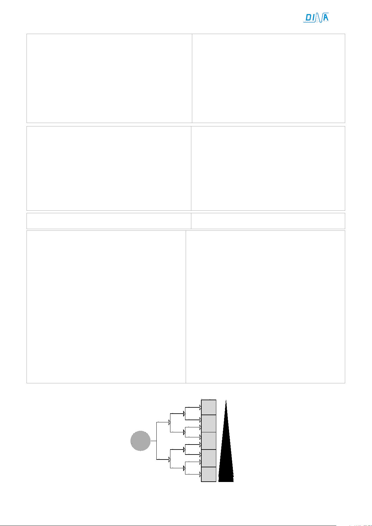
Risikograf zur Bestimmung des PLr für jede
Risk diagram to determine the PLr for every safety
Legende und Risikoparameter
Legend and Risk parameters
H
L
P1
P2
P1
P1
P1
P2
P2
P2
Start
a
b
c
d
e
F1
F2
F2
F1
S1
S2
PL
r
• Die Grenzen des SRP/CS beginnen an den Eingangssig-
nalklemmen und enden an den Klemmen der kontaktbehafteten Freigabepfade.
• Änderung, Reparatur und Instandhaltungen durch
Anwender sind nicht erlaubt. Getroffene
Fehlerausschlüsse gelten unverändert.
• Die Anforderungen unten sind in dieser
Betriebsanleitung beschrieben:
• Beschreibung der Schnittstellen zu SRP/ CS und
Schutzeinrichtungen (modulabhängig beschrieben)
• Anzeigen und Alarme
• Muting und zeitweiliges Aufheben der
Sicherheitsfunktionen
• Betriebsarten allgemein
• Instandhaltung, Checklisten und Ersatz interner Teile
(trifft nicht zu)
• Mittel zur leichteren und sicheren Fehlersuche
• Testintervalle (trifft nicht zu)
• Für die notwendigen Angaben siehe Inhaltsverzeichnis.
Sicherheitsfunktion
• The boundaries of the SRP/CS start at the input
signals clamps and will end at the clamps of the
contact driven enable path.
• Changing, repair and maintenance by the user is
not intended. Exclusions of errors made, will stay
valid unchanged.
• The requirements below are described in this
instruction manual:
• Description of the interfaces to SRP/ CS and safety
0equipment (described module dependent)
• Indicators and alarms
• Muting and temporary disabling of the safety
functions
• Operation mode’s general descriptions
• Maintenance, Checklists and internal spare parts
(not valid)
• Tools for easy and safe troubleshooting
• Test intervals (not valid)
• For the necessary information see contents.
function
L: niedriger Beitrag zur Risikoreduzierung
H: hoher Beitrag zur Risikominderung
: erforderlicher Performance Level
PL
r
S: Schwere der Verletzung
S1: leichte (reversible Verletzung)
S2: ernste (irreversible Verletzung, Tod)
F: Häufigkeit und/oder Dauer der
Gefährdungsexposition
F1: selten bis weniger häufig und/oder die Zeit der
Gefährdungsexposition ist kurz
F2: häufig bis dauernd und/oder die Zeit der
Gefährdungsexposition ist lang
P: Möglichkeit zur Gefährdungsvermeidung der
Begrenzung des Schadens
P1: möglich unter bestimmten Bedingungen
P2: kaum möglich
L: low impact on risk reduction
H high impact on risk reduction
necessary performance Level
PL
r
S: severe of injury
S1: light (normally reversible injury)
S2: severe (irreversible injury including dead)
F: frequency and/or duration of the danger situation
F1: seldom to infrequent and/or short exposition to
danger situation
F2: frequent or constant and/or long exposition
to danger situation
P: possibilities to circumvent the danger or limitation
of damage
P1: possible under certain conditions
P2: nearly impossible
DNDS Modular Original Betriebsanleitung Original Instruction Manual
Sicherheitstechnik
Stand 19.02.2018
Date 2018-02-19
Seite 8 von 31
page 8 of 31
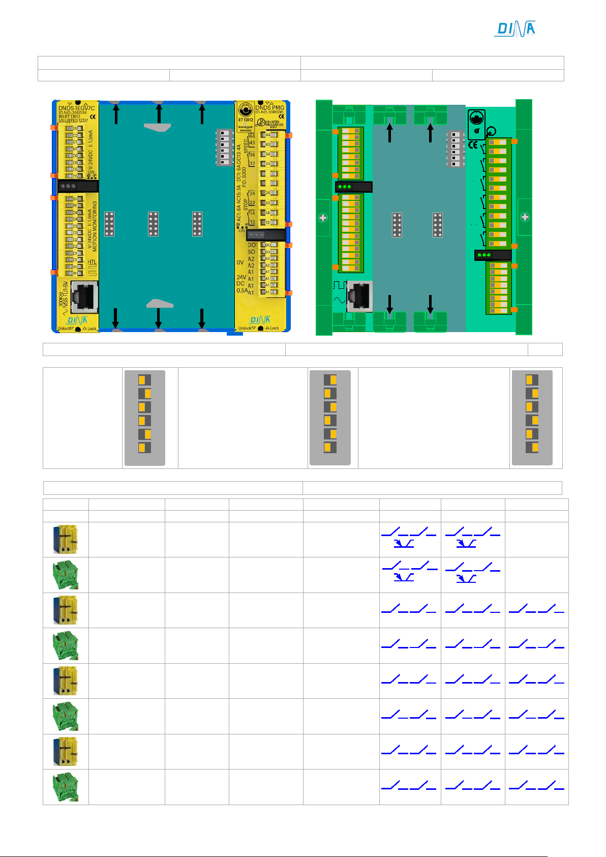
Aufbau
Mounting
Metall Gehäuse
metal housing
Kunststoff Gehäuse
Synthetically housing
4
3
2
1
5
6
on
Modulführung
Module guideway
IN1
IN2
D1
D1
D2
D2
D3
D3
D4
D4
R1
SH
D6
D6
D5
D5
MT
24V
O1
O2
1-5V
1VSS
1Vpp
300KHz
SPEED
STOP
ON
ON
SPEED
STOP
A1
24V
DC
0.5A
A2 0V
DINA ELEKTRONIK
D-72649 WOLFS CH LU GE N
ID-No:10VM00
DNDS VM
1ZD7
US LISTED
IND.CONT.EQ
R
L
U
STOP
SPEED1
SPEED2
P.D. B300
DC1: 6A DC 13: 4A
AC1: 6A AC15: 3A
B
G
-
P
R
U
F
Z
E
R
T
ET 13012
Sicherheit geprüft
tested safety
44
43
34
33
24
23
14
13
68
67
58
57
Q
E2
E1
A2
A1
A1
A1
A1
DNDS MODULAR OUTPUT MODULE
START
STOP
4
3
2
1
5
6
on
Modulführung
Module guideway
Einstellung am Rack
Adjustment at the rack
on
6
5
4
3
2
1
DNDS GM, GMG
on
6
5
4
3
2
1
DNDS GM, GMG
on
6
5
4
3
2
1
Produktvarianten
Product variants
Überwachung
DNDS
Monitoring
DNDS
DNDS
STOP
SPEED
SPEED 2
13
1423
24
OS
33 3443
44
OD
13 1423
24
OS
33 3443
44
OD
13 1423
24
33 3443
44
57 58
67
68
13 1423
24
33 3443
44
57 5867
68
13 1423
24
33 3443
44
53 5463
64
13 1423
24
33 3443
44
53 54
63
64
13 1423
24
33 3443
44
57 5867
68
13 1423
24
33 3443
44
57 5867
68
DNDS
OM, PM, PMG
GM V1, GMG V1
VM, VMG
Modul links vom GM, GMG
steuert SPEED2
►
Module left of GM, GMG
►
1PMG - 8PMG 1 - 8 1EG +1RG PMG
1M – 8M
1PM - 8PM
1VMG - 8VMG 1 - 8 1EG + 1RG VMG
1VM - 8VM 1 - 8 1E + 1R VM
2GMG - 8GMG 2 - 8 1EG + 1RG GMG
2GM - 8GM 2 - 8 1E + 1R GM
1GMG - 8GMG V1 1 - 8 1EG + 1RG GMG V1
1GM - 8GM V1 1 - 8 1E + 1R GM V1
controls SPEED 2
1 - 8 1E + 1R
Beide Module links vom GM,
GMG steuern SPEED2
►
Both modules left of GM, GMG
control SPEED2
OM
PM
DNDS Modular Original Betriebsanleitung Original Instruction Manual
Sicherheitstechnik
Stand 19.02.2018
Date 2018-02-19
Seite 9 von 31
page 9 of 31
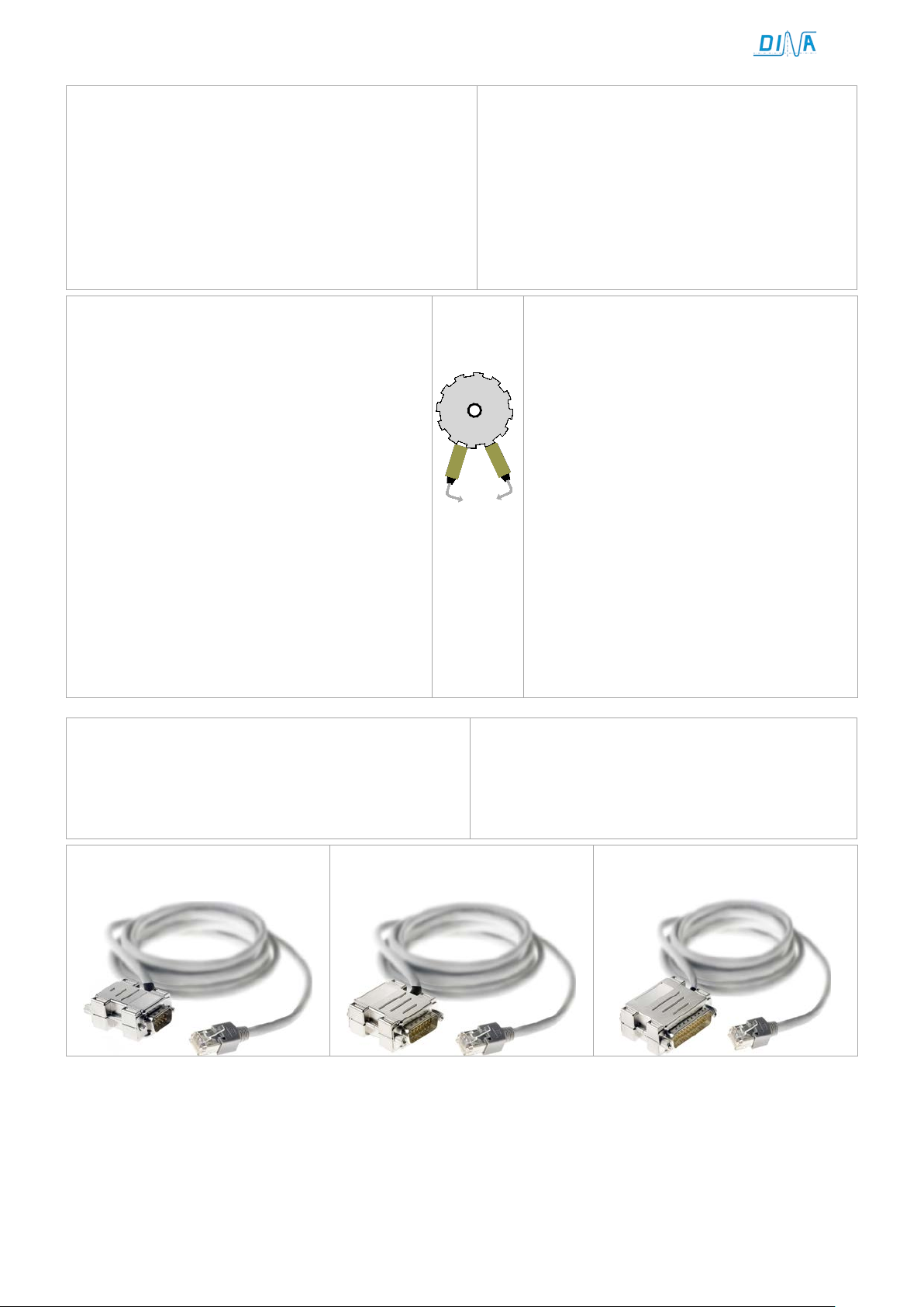
Gerätebeschreibung
Product Description
Eingangsmodule
Zahnrad
Gear
Sensor
Sensor
IN1IN2
Input modules
Kabeladapter
Cable adapter
• DNDS arbeitet mit einer Betriebsspannung von 24V DC.
• Das Gerät ist zur Montage auf einer 35mm Hutschiene.
• Die Funktionsmodule sind in steckbar einem Rack.
• Bis zu 8 Eingangsmodule und ein Ausgangsmodul sind
in einem Rack möglich.
• Alle Anschlüsse sind steckbare Federkraftklemmen.
• Das DNDS dient der sicheren Überwachung einer
rotierenden bzw. linearen Bewegung.
• Die Bewegungserfassung einer Achse erfolgt
über ein inkrementelles oder Resolver Messsystem bzw. 2 PNP Sensoren an IN1 und IN2.
• Das Messsystem wird über den Kabeladapter
DNDA an DNDS angeschlossen.
• Die PNP Sensoren werden über die Klemmen IN1
und IN2 am Eingangsmodule angeschlossen.
• Die Montage der Sensoren muss sicherstellen,
dass im Stillstand mindestens ein Sensor aktiv
ist.
• Statusanzeige über LED
• Auswahl der max. Drehzahlen erfolgt über DIP
Schalter und Klemmen.
• DNDS works with24V DC power supply.
• The unit is mountable on a 35mm DIN rail.
• The function modules are pluggable in a rack.
• Up to 8 input modules and one output module are
possible in a rack.
• All connections are pluggable spring loaded
clamps.
• The DNDS is designed for safe monitoring of
rotary respectively linear motion.
• The movement detection of an axle happens
via an incremental or resolver measuring
system respectively 2 PNP sensors at IN1
and IN2.
• The measuring system is to connect to the
DNDS using the cable adapter DNDA
• The PNP sensors are to connect via the ter-
minals IN1 and IN2 at the input modules.
• The mounting of the sensors has to enable
at least one active sensor during standstill.
• Status indicators via LED
• Setting of the maximal speeds happens via
DIP switches and terminals.
Zur Anbindung der Überwachung an das Achsenmesssystem sind verschiedene Kabeladapter mit verschiedenen Steckverbindungen lieferbar. Siehe Betriebsanleitung „Kabeladapter“.
DNDA 9/8
DNDA 15/8
To connect the monitoring with the axle feedback
measuring system different cable adapters with different connectors are available. See instruction manual
“Cable adapter”.
DNDA 25/8
DNDS Modular Original Betriebsanleitung Original Instruction Manual
Sicherheitstechnik
Stand 19.02.2018
Date 2018-02-19
Seite 10 von 31
page 10 of 31
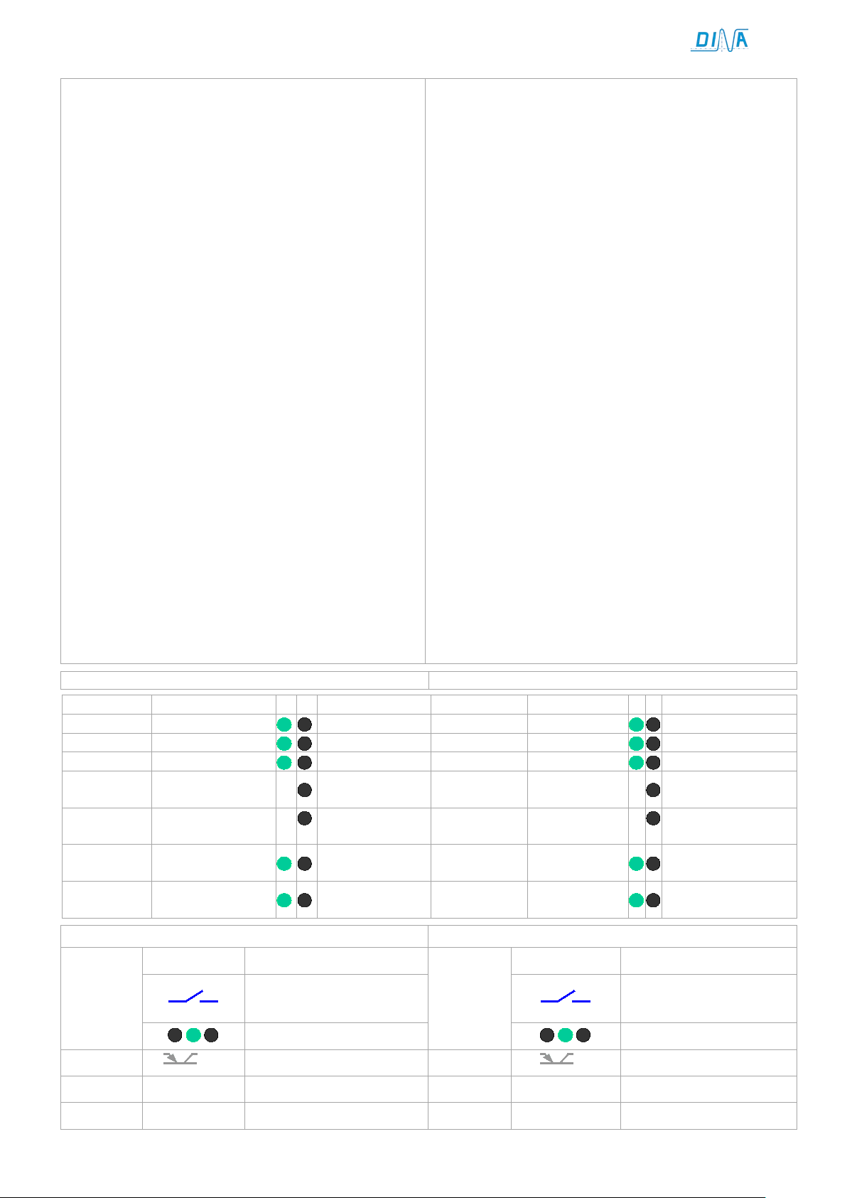
Funktion der Klemmen
Function of the terminals
Funktion der LED Anzeige
Function of LED display
LED
LED
Mitte
Betriebsspannung
Aus
middle
Power supply
Off
links
Stillstand
Bewegung
left
Standstill
Movement
rechts
V < Vmax
V > Vmax
right
V < Vmax
V > Vmax
During
Kein
During
No measuring
links oder
Spur A oder B
links oder
Verhalten bei Störungen
Performance on failure
Ausgänge
Ursache und Abhilfe
Outputs
Reason and repair
Einstellung der
Adjustment of input
Inkrementell / Resolver?
Incremental or resolver?
aus
Kein Messsystem
off
No measuring system
Falscher Kabeladapter
wrong cable adapter
Quittierung
Fehlerbeheben
Betriebsspannung 2s aus
Quit
remove failure
Power supply 2s off
• IN1, IN2 für 2 PNP Sensoren als Messsystem.
• Anschluss IN2 an 24V, IN1 offen: unterdrückt
Modulfunktion nur für besondere Fälle vorgesehen.
• D-Klemmen an 1E V6, V7, V9 / 1R V1 / 1EG V9 / 1RG V1
Auswahl der Drehzahl im Automatik betrieb
nur aktive bei mindestens eine F-Klemme an 24V
• F-Klemmen:
Reduzierung der Auswahl an D-Klemmen 100-25%
Umschalter zwischen automatikbetrieb (Fx an 24V)
und Einrichtbetrieb (F offen)
• R1-Klemme:
Zur Auswahl des Halbautomatikbetriebs
R1-Klemme ist nur aktiv bei offenen F-Klemmen.
• SH-Klemme: Zur Auswahl der des Einrichtbetriebs
SH ist nur aktiv bei offenen R1- und F-Klemmen.
• D-Klemmen an 1E, 1EG V7A, V7C / 1R, 1RG V2, V3C
Auswahl der Drehzahl im Automatikbetrieb
Umschalter zwischen automatikbetrieb (Dx an 24V)
und Einrichtbetrieb (D offen)
• M-/ MT-Klemmen:
Unterdrückung der Modulfunktion nur in besonderen
Fällen an 24V anschließen.
• R1-Klemme: Zur Auswahl des Halbautomatikbetriebs
R1 ist nur aktiv bei offenen D-, M- bzw. MT-klemmen.
• SH-Klemme: Zur Auswahl der des Einrichtbetriebs
SH ist nur aktiv bei offenen D-, M- bzw. MT-Klemmen.
• Alle Klemmen sind 10ms einschalt- und 1s
ausschaltverzögert
• IN1, IN2 for 2 PNP sensors as measuring system.
• Connection IN2 to 24V, IN1 open: muting the module
function only to use if necessary.
• D-Terminals at 1E V6, V7, V9 / 1R V1 / 1EG V9 / 1RG V1
setting of the speed during the automatic function
mode active only if at least one F-terminal is at 24V.
• F-Terminals:
reduction of the selection at D-Terminals 100-25%
Switch over between automatic mode (Fx at 24V)
and tool-setting function mode (F = off)
• R1-Terminal:
To select the semi-automatic mode
R1-Terminal is only active if the F-Terminals are off.
• SH-Terminal: To select the tool setting mode
SH is only active if R1 and F-Terminals are off.
• D-Terminals at 1E, 1EG V7A, V7C / 1R, 1RG V2, V3C
Selection of the speed during the automatic mode
Switch over between automatic mode (Dx at 24V)
and tool-setting function mode (D = off)
• M-/ MT-Terminals:
muting of the module function to connect to 24V if
necessary only
• R1-Terminal: To select the semi-automatic mode
R1 is only active if the D-, M- respectively MT are off.
• SH-Terminal: To select the tool setting mode
SH is only active, if D-, M- respectively MT are off.
• All terminals are10ms switch on and 1s switch off
delayed.
rechts Im Stillstand
links/rechts Im Stillstand
Eingangsmodul
Ausgangsmodul
rechts
rechts
Nach V > Vmax right
Messsystem
fehlt
Interner Fehler left or right Output module
Eingangsmodule
standstill
left/ right
standstill
left or right Input module
After V > Vmax
system
No trace A or B
Internal error
modules
 Loading...