

DINA DN3PW1 Original Instruction Manual
DN3PW1
Original Betriebsanleitung
Original Instruction Manual
Drei Phasen Spannungswächter
mit einstellbarer Reaktionszeit
Three phases voltage monitoring
with adjustable reaction time
QUALITÄTSMANAGEMENT SYSTEM
DQS Zertifiziert nach
DIN EN ISO 9001: 2015
Reg.-Nr.67542-01

Sicherheitsbestimmungen
Inhaltsverzeichnis
Seite
Contents
Page
Sicherheitsbestimmungen
2
Safety regulations
2
Bestimmungsgemäße Verwendung
2
Intended usage
2
Gerätebeschreibung
3
Unit Description
3
Hinweise zur Messspannung an U, V und W
3
Note to the measuring voltage at U, V and W
3
Funktionsbeschreibung
4
Function Description:
4
Einstellung der Reaktionszeit
5
Adjustment of off-delay reaction time
5
Einstellung der Messspannungstoleranz
5
Adjustment of the measuring voltage tolerance
5
Technische Daten
6
Technical data
6
Maßbilder
7
Dimensions
7
Einbau
7
Fitting
7
Ausbau
7
Remove
7
Sicherheitsbestimmungen
Safety regulations
Bestimmungsgemäße Verwendung
Intended usage
• Das Gerät darf nur von einer Elektrofachkraft oder
unterwiesenen Personen installiert und in Betrieb
genommen werden, die mit dieser Betriebsanleitung
und den geltenden Vorschriften über Arbeitssicherheit und Unfallverhütung vertraut sind.
• Beachten Sie die VDE- sowie die örtlichen
Vorschriften, insbesondere hinsichtlich der
Schutzmaßnahmen.
• Transport, Lagerung und im Betrieb entsprechend
EN 60068-2-6 ein. siehe technische Daten.
• Durch eigenmächtige Umbauten erlischt jegliche Ge-
währleistung.
• Montieren Sie das Gerät in einem Schaltschrank.
Staub und Feuchtigkeit können sonst zu
Beeinträchtigungen der Funktionen führen.
• Sorgen Sie an allen Ausgängen bei kapazitiven und
induktiven Lasten für eine ausreichende
Schutzbeschaltung.
• Das Gerät ist unter Berücksichtigung der nach
VDE 0106 Teil 100 geforderte Abstände einzubauen.
• Das Gerät muss sachgerecht entsorgt werden am
Ende seiner Lebenszeit.
• The unit may only be installed and operated by those
who are qualified electrical engineers or have
received sufficient training and are familiar with
both these instructions and the current regulations
for safety at work and accident prevention.
• Follow VDE, EN as well as local regulations
especially as regards preventative measures.
• Transport, storage and operating conditions should
all conform to EN 60068-2-6. See technical details.
• Any guarantee is void following unauthorised
modifications.
• The unit should be mounted in a cabinet; otherwise
dampness or dust could lead to functional
impairment.
• Adequate fuse protection must be provided on all
output contacts especially with capacitive and
inductive loads.
• The unit must be installed following the
specification of VDE 0106 part 100 regarding the required distances
• The unit must be disposed of properly when it
reaches the end of it service life.
Überwachung der Betriebsspannung einer Anlage
Phasen und Spannungswert können überwacht werden.
Prüfgrundlage:
• 2006/95/EWG „Niederspannungsrichtlinie"
• 2004/108/EG „
EMV-Richtlinie“, EN 55011 +A1, EN 61000-6-2
• DIN EN 60947-5-1
Betriebsanleitung Stand: 09.03.2018 Seite 2 von 8 Instruction Manual Date: 2018-03-09 Page 2 of 8
Monitoring of the power supply of a plant
The phases and the voltage value can be monitored.
Testing base:
2006/95/EWG „Low voltage recommendation"
• 2004/108/EG
EMV guidance EN 55011 +A1, EN 61000-6-2
• DIN EN 60947-5-1
Gerätebeschreibung
Gerätebeschreibung
Unit Description
• Das Gerät ist in einem 22.5mm Kunststoffgehäuse
• The unit is mounted in a 22.5mm synthetically
U, V, W:
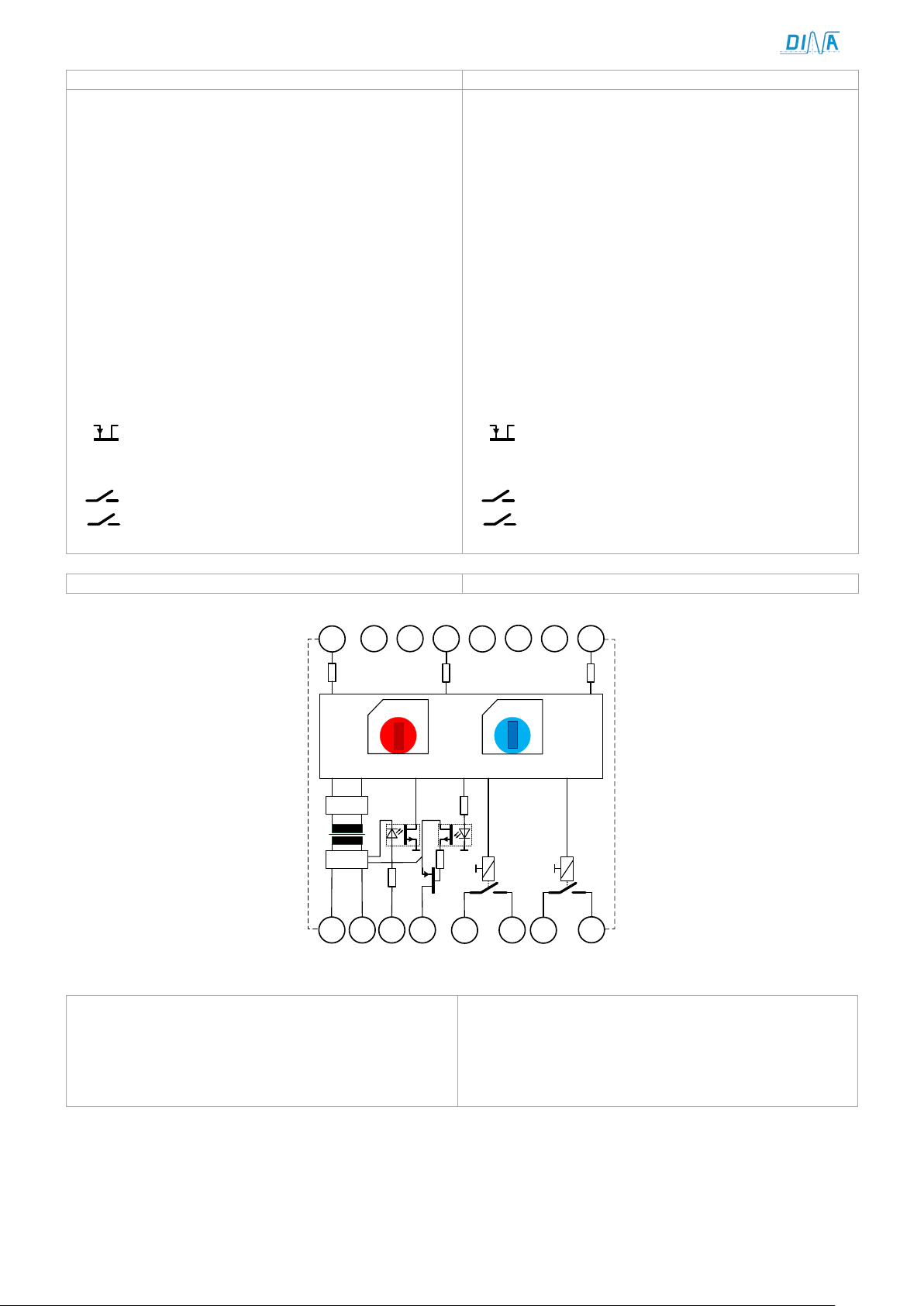
Schema
Schematic
+
-
A1 A2 IN1 O3 13
14
23
24
+
-
0
0
10-100ms
10-143V±5%
14 16
13
12
11
109
15
1
2
3
4
5 6
7
8
U
V
W
3x200-550V AC
24V DC
Hinweise zur Messspannung an U, V und W
Note to the measuring voltage at U, V and W
untergebracht zur Montage auf einer Normschiene.
• Anschluss ist über steckbare Federkraftklemmen.
U, V, W: Messeingänge
Eingangsspannung: 3x400V AC
IN1: Eingang zur Deaktivierung der Funktion z.B.
während Inbetriebnahme
Eingangsspannung: 24V DC
Der Ausgang ist aktive, wenn IN1 mit 24V
verbunden ist.
Die LED K1, K2 blinken
A1/ A2: Betriebsspannung 24V DC
Anzeige über LED Power
O3
Status
13
23
Anzeige über LED K1
: Positivschaltende Ausgang für Funktion
14,
24: Kontaktausgänge für Funktion Status
housing to mount on a DIN Rail.
• Wiring via pluggable spring loaded terminals.
measuring inputs
Input voltage: 3 x 400V AC
IN1: Input to deactivate the function as example
during the installation.
Input voltage: 24V DC
The output is active if IN1 connected to 24V.
The LED K1 and K2 flash.
A1/ A2: Input for Power supply: 24V DC
Indication via LED Power
O3
Output for function status
13
23
Indication via LED K1
: Positive switching output
14,
24: Contact outputs for function status
• Das Gerät lernt nach dem Einschalten der
Betriebsspannung die anliegende Messspannung.
• Dieser Lernvorgang wird alle 6s wiederholt.
Betriebsanleitung Stand: 09.03.2018 Seite 3 von 8 Instruction Manual Date: 2018-03-09 Page 3 of 8
• The unit learns after power supply switch-on the
actual measuring voltage.
• This action is repeated every 6s.
 Loading...