

Dimplex XL12N, XL24N, XLS12N Automatic, XLS18N Automatic, XL18N Installation Instructions Manual
...Page 1
Installation Instructions
Dimplex Ultra-Slim Storage Heaters
Models XL12N, XL18N, XL24N
Twin Sensor Models XLS12N Automatic,
XLS18N Automatic, XLS24N Automatic
(96513 Iss. 21)
IMPORTANT
These instructions should be read carefully and retained for future reference.
Note also the information given on the appliance.
This heater is VERY HEAVY. In order to maintain stability
and to ensure its future safety in use, it is essential that
the heater is FIXED SOUNDLY TO A WALL and that the
feet are mounted on a FIRM, LEVEL SURFACE. Care
should be taken to avoid irregular surfaces, such as may
result from tiled surrounds partially protruding under the
heater. It is important that the following instructions are
strictly followed.
IT IS IMPORTANT THAT THE FIXING DEVICE CHOSEN IS
APPROPRIATE TO THE WALL MATERIAL TO WHICH THE
HEATER IS BEING FIXED. SOME MODERN INTERNAL
BUILDING MATERIALS ARE VERY LOW DENSITY BLOCK
AND REQUIRE SPECIALISED FIXING DEVICES TO
PROVIDE A SAFE, SECURE INSTALLATION.
THE HEATER MUST BE INSTALLED WHERE IT IS IMPOSSIBLE
FOR SWITCHES AND OTHER CONTROLS TO BE TOUCHED
BY A PERSON USING A BATH OR SHOWER.
The installation of this appliance should be carried out by
competent personnel and be in accordance with the current
IEE wiring regulations. For the assembly of the heater tools
required are a No. 2 pozidriver, an electrical screwdriver
with a 4mm wide blade and a 8mm AF open ended or box
spanner. A small mirror will aid insertion of the front panel
retaining screws.
Only Heat Resisting Cable (min. rating T85) should be used.
DO NOT COVER OR OBSTRUCT the surfaces of the
appliance.
DO NOT INSTALL the heater immediately below a fi xed
socket outlet.
DO NOT POSITION under windows where curtains may
contact the heater. (See minimum clearances, stage 6).
DO NOT PLACE OBJECTS in contact with the heater.
If, during any reassembly of the heater, a part of the thermal
insulation shows damage or deterioration which may impair
safety, it should be replaced with an identical part.
Connection to a 30 amp Ring Circuit
XLN/XLSN STORAGE HEATERS SHOULD NOT BE CONNECTED TO A 30 AMP RING CIRCUIT.
XL/XLS24N STORAGE HEATERS SHOULD NOT BE CONNECTED TO A FUSED SPUR.
A means for disconnection must be incorporated in the fi xed wiring by a double pole switch with a contact
separation of a minimum of 3mm and in accordance with the current IEE Wiring Regulations.
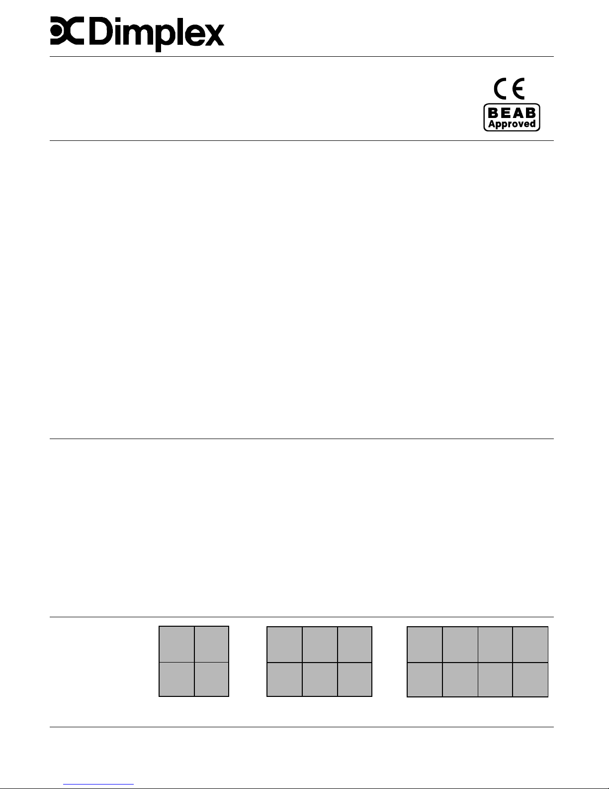
Bricks are in packs of two.
The pack catalogue
number is XT 8300
XL12/XLS12N - 12kWh
8 Bricks (4 Packs)
XL18/XLS18N - 18kWh
12 Bricks (6 Packs)
XL24/XLS24N - 24kWh
16 Bricks (8 Packs)
IMPORTANT - Due to the newness of materials the heater will produce a slight smell for the fi rst few days of operation.
ROOMS MUST BE WELL VENTILATED AND YOUNG CHILDREN, CAGED BIRDS, OR PERSONS WITH RESPIRATORY
COMPLAINTS MUST NOT REMAIN IN CLOSE PROXIMITY TO THE HEATER DURING THE COMMISSIONING PERIOD.
To commission the heater set both controls to maximum and leave for a minimum of 48 hours, after this period the controls
should be adjusted for everyday use - see operating instructions.
This appliance is not intended for use by persons (including children) with reduced physical, sensory or mental capabilities, or
lack of experience and knowledge, unless they have been given supervision for instruction concerning use of the appliance
by a person responsible for their safety. Children should be supervised to ensure that they do not play with the appliance.
This product complies with the European Safety Standards EN60335-2-30 and the European Standard Electromagnetic Compatibility (EMC) EN55014, EN60555-2 and EN60555-3.
These cover the essential requirements of EEC Directives 2006/95/EC and 2004/108/EC
Page 2
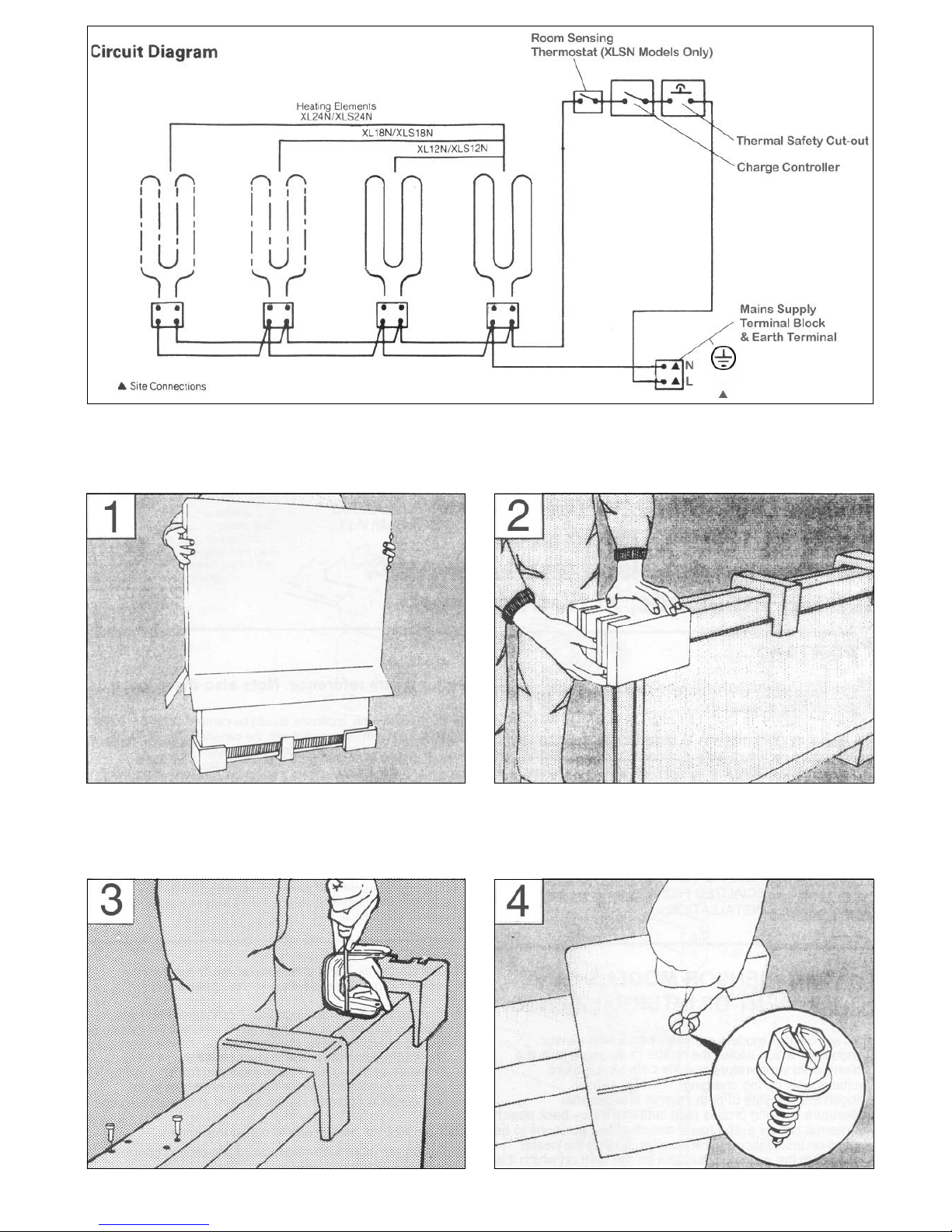
Assembly of heater
1. Invert the carton and carefully lift carton off heater. Do
not remove internal packaging pieces at this stage!
2. Remove the feet and accessories bag from corner
fi ttings (accessories bag is located within one of the feet).
3. Secure the feet to base of heater using the Taptite
screws provided (two for each foot). It is necessary on
XL12N/XLS12N models, to remove base corner packaging
pieces to locate feet in position.
4. Loosen hexagon head front panel securing screws, by
1 - 2 turns using screwdriver through aperture in each end
packing piece.
Page 3
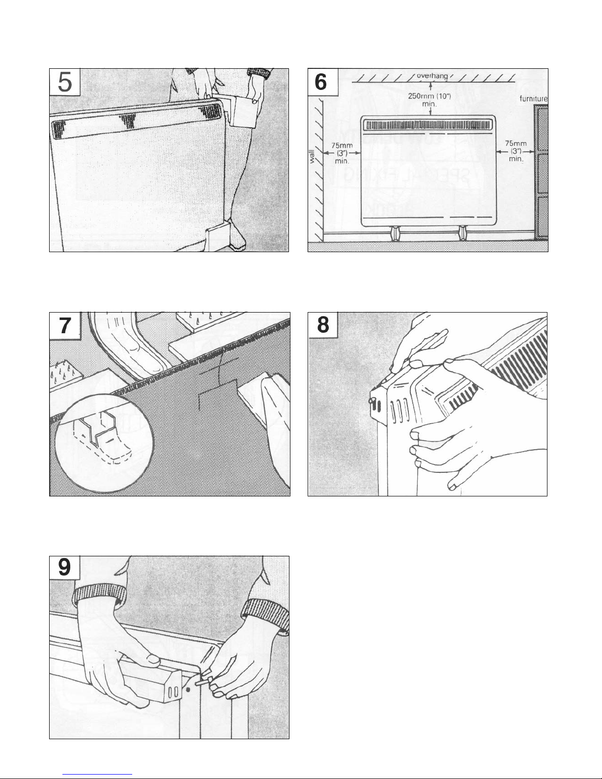
6. Position heater against wall in intended fi nal position,
taking note of the minimum fi xing dimensions.
If fi tted, the Dimplex storage heater shelf should be fi xed
in accordance with the instructions enclosed with the shelf.
7. If the fl oor is carpeted then the carpet should be slit and
underlay cut away to allow the feet to rest fi rmly on the
fl oor. Carpet gripper must be locally removed so that the
feet may rest in a level position.
8. Having prepared, where necessary, the fl oor, the
position of the wall bracket should be marked on the wall.
5. Stand heater on its feet and remove all packaging
pieces.
9. Remove wall fi xing bracket from heater by removing
the screws at each end.
10. Four fi xing positions must be chosen for the 24N, three
for the 18N and two for the 12N . Mark the positions for the
fi xing holes - two at the extreme ends and the others spaced
evenly between them. Remove the bracket from the wall,
drill the holes in the positions marked, and insert suitable
fi xings detailed in Steps 11 and 12. Secure the wall bracket
to the wall.
Page 4

11. Solid Brick/High Density Block Walls. (See step 12
if walls are low density block.) These must be drilled
and plugged with the No. 10 size plastic inserts provided.
The correct size of drill (8mm) should be used and the
hole should be drilled to a depth of 15mm greater that the
length of the plastic insert so that the fi xing is made below
the plaster layer.
12. Low Density Block Walls. A specialised fi xing, such
as the Unifi x LB70, should be employed following closely
the manufacturer’s instructions.
Panelled Internal Walls. Here it is best to locate the
studding and use No. 10 size woodscrews. Where it is
not possible to locate the studding use type M5 Rawlplug
INTERSETS on securely fastened plasterboard panelling.
For other wall panel materials the wall panel manufacturer
should be consulted for details of suitable wall fi xing
devices.
13. If left hand cable connection is required, the mains
lead must be secured to the back of the heater using ties
provided in the fi xing kit. Ensure suffi cient spare cable is
available to make the mains connection.
Page 5

14. Secure heater to wall fi xing bracket by replacing the
two screws removed in step 10 (do not fully tighten these
screws until the bricks are loaded into the heater as
some settling of the heater may occur). The feet and wall
mounting arrangement are designed to accommodate
skirting board sizes up to 25mm (1”) thick. To avoid
obstructing the airfl ow to the rear of the heater the
following must be strictly adhered to:
(a) For skirtings higher than 100mm (4”) it will be
necessary to position the heater with the screws attached
through the alternative fi xing slots to the front.
(b) For skirtings having a height in excess of 150mm (6”)
it will be necessary to reduce the height of the skirting to
150mm (6”) over the entire length of the heater plus 25mm
(1”) at either end.
15. Remove bottom front panel securing screws. These
were loosened in step 4 and should be easily unscrewed
by hand.
16. Pull bottom of front panel forward to disengage it from
bottom of heater.
17. Still holding the bottom of front panel forward, lift
upwards to disengage top edge of front panel from groove
on heater top panel 1, and remove front panel from
heater 2.
18. Remove the protective polystyrene packing from
the front inner skin panel and discard. Remove screws
retaining front inner skin.
Page 6

23. Replace the element which had been removed by
carefully passing the ends through the base insulation
slots into the terminal blocks below. Position the insulator
on the element end in contact with the terminal block
ceramic as shown, and tighten the connection screws. At
this point check that all element connections are tight.
21. Remove one element to allow access for the back
row of bricks. On the XL/XLS24N remove the element to
the right of centre, on the XL/XLS18N remove the central
element and on the XL/XLS12N remove the left hand
element. Loosen the two screws securing the element tails
in the ceramic block, and lift the element up and out of the
heater.
22. Position the bottom rear layer of bricks with the recess
over the slots in the base insulation slab. Push the bricks
fi rmly to the back of the heater, then fi t the top row of
bricks.
19. Carefully lift the bottom of the front inner skin panel
out of the retaining fl ange at the base of the heater, taking
care not to damage the insulation attached to this panel.
20. Remove the internal packing by sliding it up and off
the elements, taking care not to damage the insulation.
Page 7

24. Fit the front bricks with the airways facing inwards.
25. Re-fi t the inner front panel/insulation assembly,
ensuring the bottom edge of the panel is located behind
the base fl ange. Make sure all screws removed in
Operation 18 are replaced securely.
26. Check that the damper mechanism within the heater
functions freely by rotating the left hand control knob.
Check also that the right hand (input) knob rotates freely.
27. Introduce mains supply cable through the cable clamp
into the terminal area, and connect in accordance with the
terminal markings. HEAT RESISTING CABLE MUST BE
USED (min. T85). Ensure that the cable is clamped so
that there is no excess cable in the terminal area. ON
NO ACCOUNT SHOULD ANY SURPLUS CABLE BE
PUSHED INSIDE OR BEHIND THE HEATER. CHECK
ALL ELECTRICAL CONNECTIONS FOR TIGHTNESS.
29. Push the bottom of the front panel towards the heater,
so that the bottom fl ange locates under the base.
28. Holding the bottom edge of the front panel towards
you, locate the top edge of the front panel in the groove at
the top of the heater.
Page 8

30. Replace the two front panel securing screws removed
in operation 15. A small mirror on the fl oor under the
heater will help location of the threaded holes in the base.
These should be tightened using an 8mm AF socket or
open ended spanner.
Ensure all screws have been fully tightened.
31. Ensuring the electricity supply is disconnected,
connect the free end of the mains cable to a suitable
double-pole switch adjacent to the appliance reinstate the electricity supply.
NOTE: The double pole switch must have a contact
separation of at least 3mm in all poles.
© GDC Group Ltd. All rights reserved.
Material contained in this publication may not be reproduced in whole or in part, without prior permission in writing.
A division of the GDC Group Ltd, Millbrook House, Grange Drive, Hedge End, Southampton SO30 2DF
Dimplex UK Limited,
Millbrook House,
Grange Drive,
Hedge End,
Southampton, SO30 2DF.
Tel: 0845 600 5111
Fax: 01489 773 050
Web-site www.dimplex.co.uk
 Loading...