

Dimplex XLF60 Owner's Manual
7215520100R00
IMPORTANT SAFETY INFORMATION: Always read this manual rst
before attempting to install or use this replace. For your safety, always
comply with all warnings and safety instructions contained in this manual to
prevent personal injury or property damage.
To view the full line of Dimplex products, please visit
www.dimplex.com
Better solutions through innovation
Owner’s Manual
Model
XLF60
2 www.dimplex.com
Table of Contents
Always use a qualied technician or
service agency to repair this replace.
!
NOTE: Procedures and techniques
that are considered important
enough to emphasize.
CAUTION: Procedures and
techniques which, if not carefully
followed, will result in damage to
the equipment.
WARNING: Procedures and
techniques which, if not carefully
followed, will expose the user to the
risk of re, serious injury, or death.
Welcome & Congratulations ...................... 3
IMPORTANT INSTRUCTIONS .....................4
Quick Reference Guide ......................... 6
Fireplace Installation ........................... 7
Framing ..............................................7
Permanent Heat Disable ................................9
Electrical ............................................10
Bathroom Use ........................................13
Final Assembly .......................................13
Wiring Diagram ............................... 16
Operation ................................... 17
Maintenance ................................. 22
Warranty .................................... 23
Technical Support ............................. 25
3
Welcome & Congratulations
Thank you and congratulations for purchasing an electric replace from
Dimplex. Please use our convenient online registration page to record
your model and serial numbers for future reference at
www.dimplex.com/register
NO NEED TO RETURN TO THE STORE
Questions with operation or assembly? Require Parts Information?
Product Under Manufacturer’s Warranty?
Contact us at: www.dimplex.com/customer_support
For Troubleshooting and Technical Support
OR Toll-Free 1-888-DIMPLEX (1-888-346-7539)
Monday to Friday 8:00 a.m. to 4:30 p.m. EST
In order to better serve you, please have your model and serial number
ready or register your product online before calling (See above)
Please carefully read and save these instructions.
CAUTION: Read all instructions and warnings carefully before
starting installation. Failure to follow these instructions may result in
a possible electric shock, re hazard and will void the warranty.
Model and Serial
Number Label

4 www.dimplex.com
When using electrical appliances,
basic precautions should always
be followed to reduce the risk of
fire, electric shock, and injury to
persons, including the following:
① Read all instructions before
installing or using this electric
replace.
② This replace is hot when in
use. To avoid burns, do not let
bare skin touch hot surfaces.
The trim around the heater outlet
becomes hot during heater
operation.
DANGER: High temperatures
may be generated under
certain abnormal conditions.
Do not partially or fully cover
or obstruct the front of this
heater.
③ Extreme caution is necessary
when any heater is used by or
near children or invalids and
whenever the unit is left operating
and unattended.
④ Young children should be
supervised to ensure that they do
not play with the appliance.
⑤ The appliance is not intended
for use by young children
or inrmed persons without
supervision.
IMPORTANT INSTRUCTIONS
⑥ Do not operate the unit after
it malfunctions. Disconnect power
at the service panel and contact
Dimplex Technical Service for
service 1-888-346-7539.
⑦ Do not use outdoors.
⑧ Never locate replace where
it may fall into a bathtub or other
water container.
⑨ To disconnect the replace,
turn the controls off, then
disconnect the circuit at the main
disconnect panel.
⑩ Do not locate the heater
immediately below a xed socketoutlet.
⑪ Do not insert or allow foreign
objects to enter any ventilation
or exhaust opening as this may
cause an electric shock or re, or
damage to the heater.
⑫ To prevent a possible fire, do
not block air intakes or exhaust in
any manner.
⑬ All electrical heaters have
hot and arcing or sparking parts
inside. Do not use in areas where
gasoline, paint, or ammable
liquids are used or stored.
5
SAVE THESE INSTRUCTIONS
⑭ Use this heater only as
described in this manual. Any
other use not recommended by
the manufacturer may cause re,
electric shock or injury to persons.
⑮ Do not burn wood or other
materials in the electric replace.
⑯ Do not strike the replace
glass.
⑰ Always use a certied
electrician should new circuits be
required.
⑱ Disconnect all power supply
before performing any cleaning,
maintenance or relocation of the
unit.
⑲ When transporting or storing
the unit and cord, keep in a
dry place, free from excessive
vibration and store so as to avoid
damage.
WARNING: Remote control
contains small batteries.
Keep away from children.
If swallowed, seek medical
attention immediately.
WARNING: Do not install
battery backwards, charge, put
in re or mix with used or other
battery types - may explode or
leak causing injury.
!
NOTE: Changes or
modications not expressly
approved by the party
responsible for compliance
could void user's authority to
operate the equipment.
CAUTION
RISK OF ELECTRIC SHOCK
DO NOT OPEN
NO USER-SERVICABLE PARTS INSIDE
IMPORTANT INSTRUCTIONS
6 www.dimplex.com
Quick Reference Guide
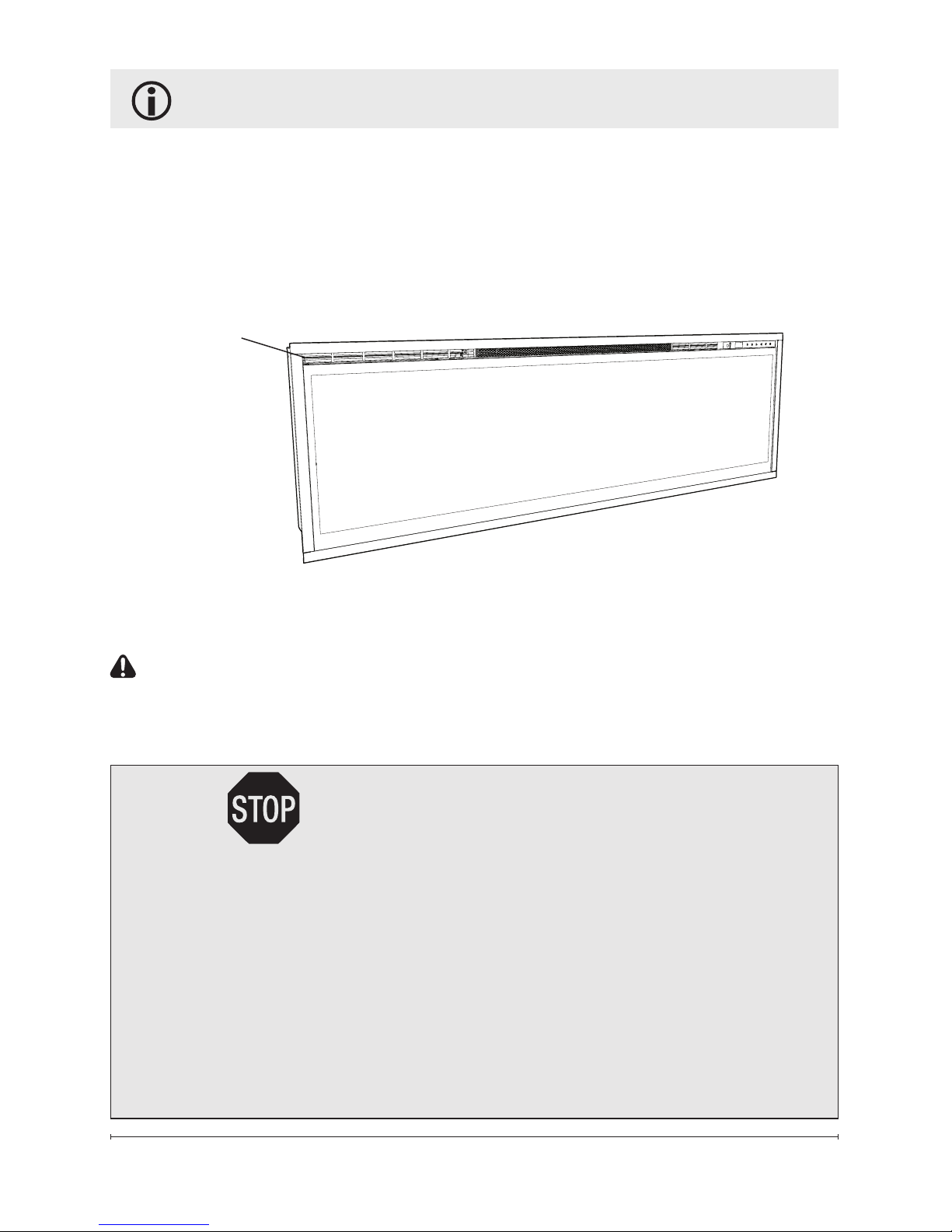
Figure 1
1. The electrical information
regarding your electric replace
can be found on the rating label
located on the top of the unit.
Please use our convenient online
registration page to record your
model and serial numbers for future
reference at:
www.dimplex.com/register
2. If you have any technical
questions or concerns regarding
the operation of your electric
replace, or require service
contact customer service at
1-888-346-7539.
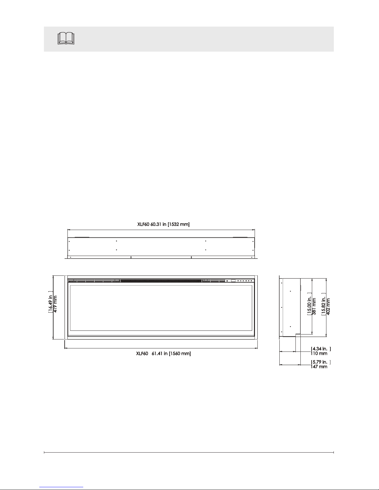
3. For dimensions of your
replace, refer to Figure 1.
16.49 in
419 mm
15.82 in.
402 mm
15.00 in.
381 mm
5.79 in.
147 mm
4.34 in.
110 mm
XLF60 60.31 in [1532 mm]
XLF60 61.41 in [1560 mm]
7
CAUTION: Ensure installation
does not allow replace to be
in direct contact with building
vapor barrier or insulation and
meets all local building code.
!
NOTE: A dedicated, properly
fused 15 Amp circuit is required,
rated for the appropriate voltage
(120V, 240V).
WARNING: Construction
and wiring must comply with
local building codes and other
applicable regulations to
reduce the risk of re, electric
shock and injury to persons.
WARNING: To reduce the risk
of re, electric shock or injury to
persons, always use a licensed
electrician.
WARNING: To reduce the
risk of re, do not store
or use gasoline or other
ammable vapors or liquids
in the vicinity of the heater.
1. Select a location that is
not susceptible to moisture
and is away from drapes,
furniture and high trafc.
2. Unpack the replace and
hardware from the box.
Fireplace Installation
!
NOTE: Leave the front glass
and partially reective glass,
safely, in the box until the time
you are ready to install it.
3. Store the replace in a safe, dry
and dust free location until you
are ready to install the replace.
Framing
CAUTION: Two people will be
required for various steps of this
procedure.
This design of this unit allows
three options for installation:
partial recess, ush mounted or
sub-surface mounted.
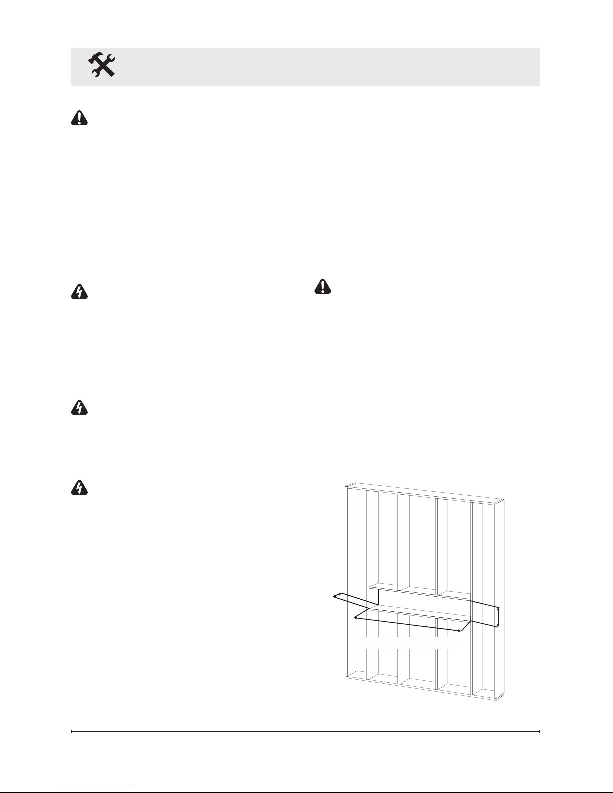
2” x 6”
5 1/2" (14.0 cm)
16"
(40.6 cm)
2” x 4”
3 1/2" (9.0 cm)
XLF60: 60 5/8" (154.0 cm)
Figure 2
8 www.dimplex.com
Fireplace Installation (continued)
CAUTION: Sub-surface
mounting should be limited
to ½ in. (10 mm) to ensure
adequate air ow of heated air
out of the rebox area.
To frame the replace:
1. Prepare a wall with a framed
opening of 16 in. (40.6 cm)
high, 60 ⅝ in. (154.0 cm) wide,
with a bottom sill that is a
minimum of 3.5 in. (9.0 cm)
deep (Figure 2). The sill can
be constructed to support the
front of the unit to allow the
power supply wires to easily
be run behind or ush with the
back of the unit and a pass
thru hole drilled for electrical
wire routing.
WARNING: The top of the
replace is to be a minimum of
8 in (20.4 cm) from the ceiling.
!
NOTE: It is recommended
that the bottom of the unit be
mounted between 30 in. (76.2
cm) and 40 in. (101.6 cm)
from the ground to maintain an
optimized viewing angle of the
ame.
WARNING: Do not attempt
to wire your own new circuits.
To reduce the risk of re,
electric shock or injury to
persons, always use a licensed
electrician.
WARNING: Ensure that the
circuit on which the replace is
to be installed has the power
cut off at the service panel
until installation is complete.
2. The unit is provided with an
installed ¾ in. (2.0 cm) trim.
Depending on the installation,
this trim can be removed by
removing the securing screws
and the 4 trim pieces.
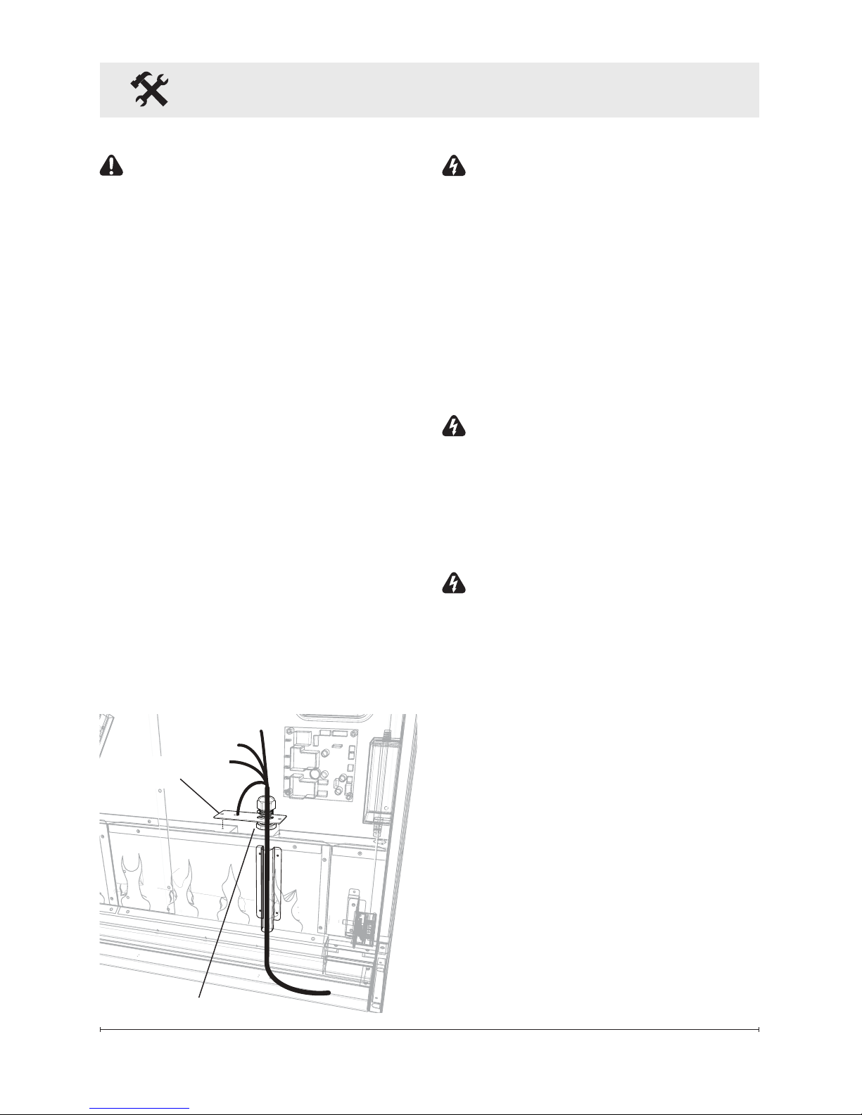
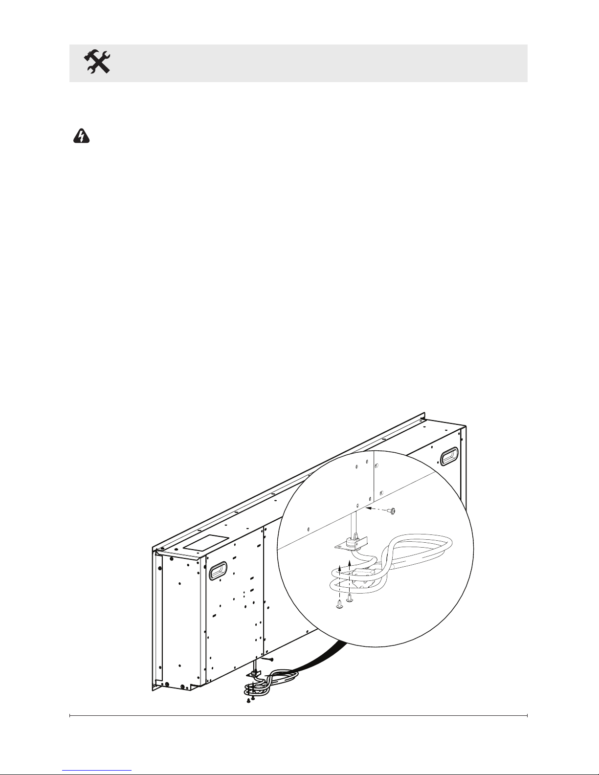
3. Ensuring a minimum of 18 in.
(46.7 cm) of slack, route the
supply power wire through a
cable clamp (not included) and
in the opening in the back of the
unit. (Figure 3)
Figure 3
Grounding
Screw
Cable Clamp
9
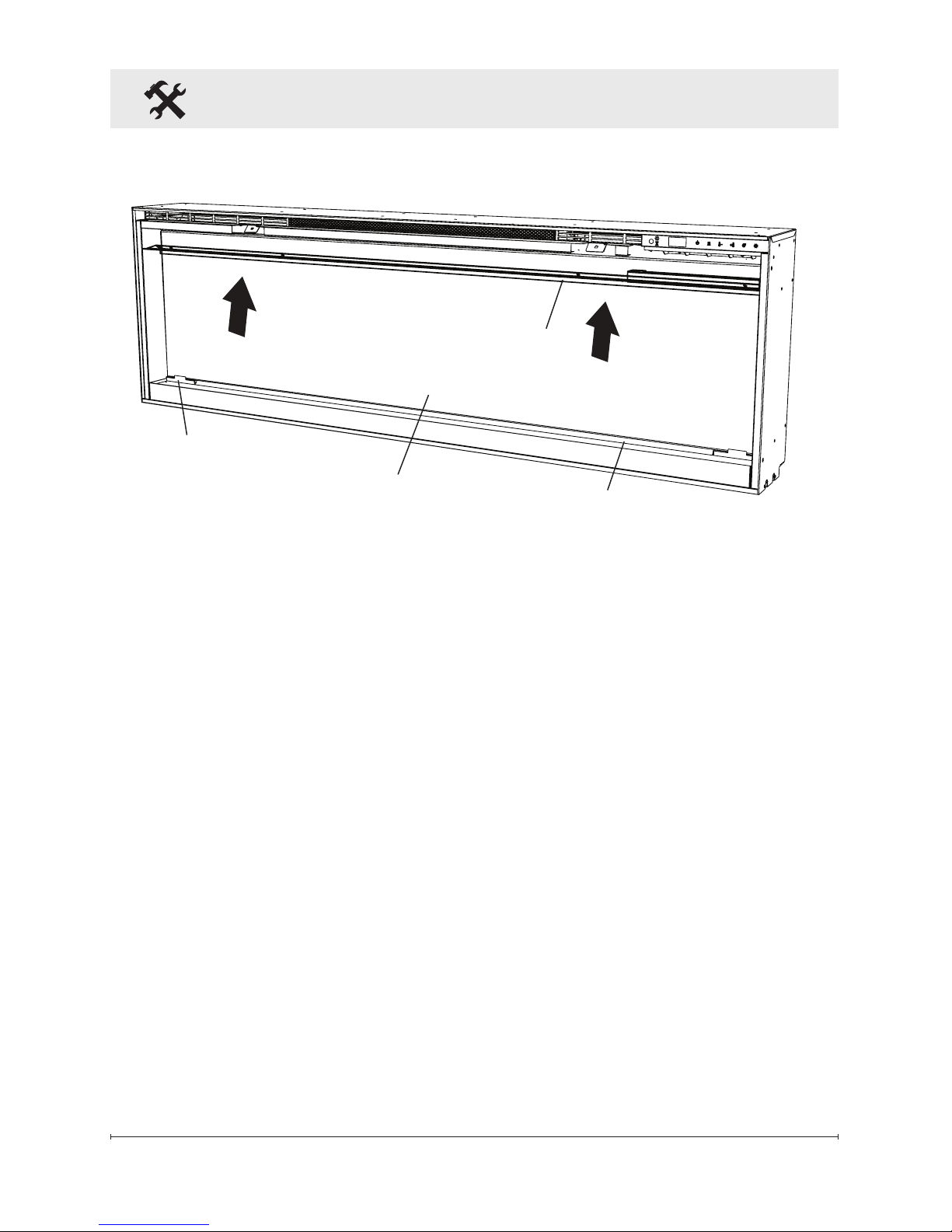
Fireplace Installation (continued)
4. Lift replace, from the bottom
and the handles located on the
back, and insert into opening to
the desired depth.
5. Using a bubble level (supplied)
ensure that the replace is level
within the framing. Adjust as
required.
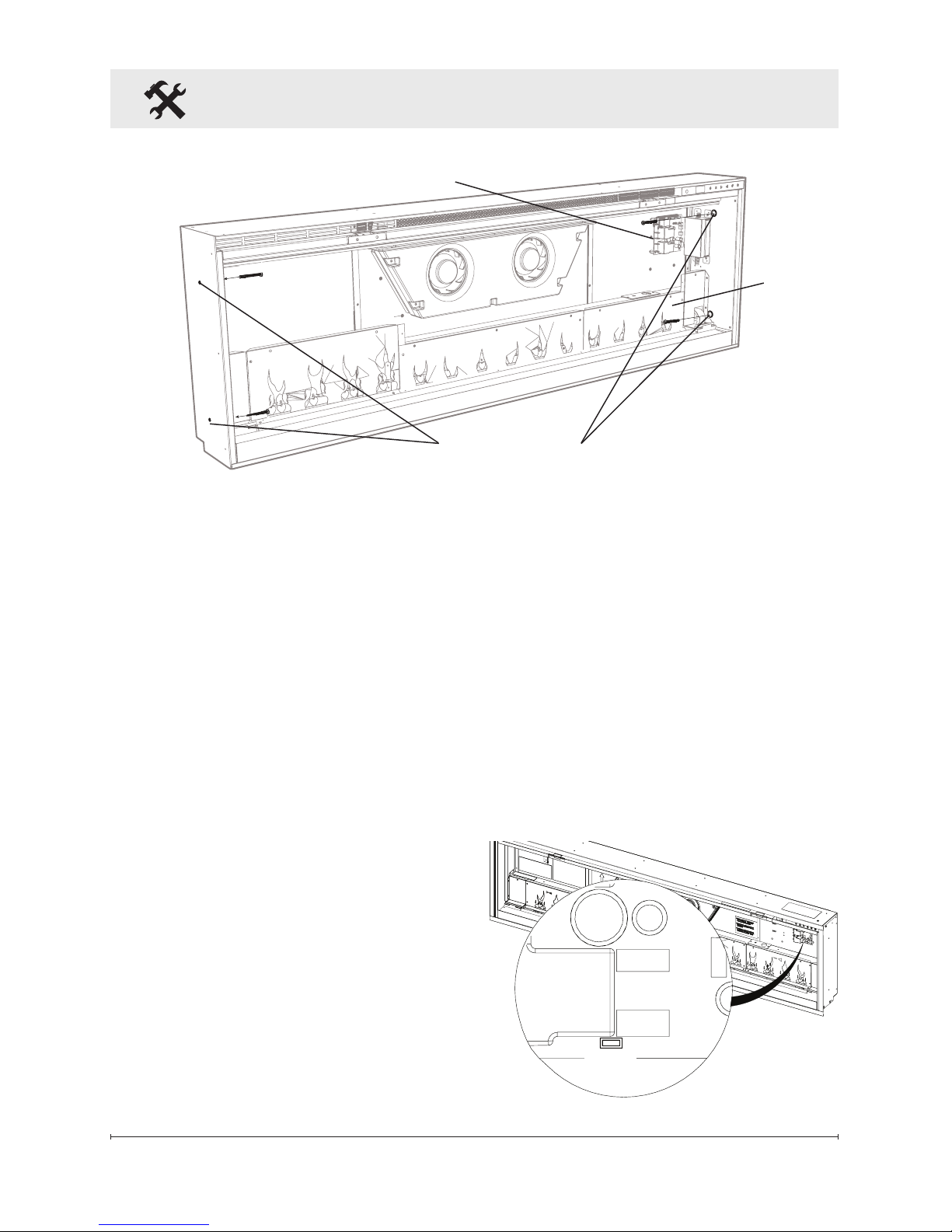
6. Drive four supplied mounting
screws through the four
mounting holes located on the
inside surface of the replace
chassis, into wall studs
(Figure 4).
Permanent Heat Disable
The replace heater can be
permanently disabled by removing
the electronic jumper on the main
control board. Disable the heater
before any other installation takes
place.
Figure 4
Mounting Holes
To disable the heater:
1. Locate the main control board
(Figure 4).
2. Pull out the electronic jumper
(shunt). The marking beside the
jumper is "HT EN" (Figure 5).
Use two conductor, non-metallic
sheath cable with ground wire
(3 wires total) for the incoming
power supply.
HT EN
Figure 5
Flame
Panel
Main Control Board
10 www.dimplex.com
Fireplace Installation (continued)
Electrical
120V Installation - Direct
Wire
CAUTION: Use the appropriate
wire to meet local and national
electrical codes for rated power
consumption.
To 120V direct wire:
1. Cut the wire to an appropriate
length.
2. Connect the L wire from the
unit to the live wire from the
power supply with a wire nut.
3. Connect the N wire from the
unit to the neutral wire from the
power supply with a wire nut.
4. Connect the G wire from the
unit to the ground wire from the
power supply with a wire nut
or attach the grounding wire
to the cover with the provided
grounding screw, by placing the
wire in-between screw and lock
washer and tighten (Figure 3).
5. Ensure that all wires are secure
and do not protrude past the
ame panel, so as not to be
visible after nal assembly.
6. Continue to the nal assembly
instructions.
120V Installation - Wall
Switch
!
NOTE: Use a single pole, single
throw (On/Off) wall switch that is
rated for a minimum of
15 amps.
CAUTION: Use the
appropriate wire to meet local
and national electrical codes
for rated power consumption.
FIREPLACE JUNCTION BOX
120 V
POWER
SUPPLY
(BREAKER
PANEL)
WHITE - N
BLACK – L1
WHITE – N
BLACK – L1
GROUND - G
WALL
SWITCH
GROUND - G
Figure 6
11
Fireplace Installation (continued)
Figure 7
Partially
Reective Glass
Partially Reective
Glass Bracket
Media Tray
To wire through a wall switch:
1. Cut the wire to an appropriate
length.
2. Connect the L wire from the
unit to the live wire from the
main power through the
wall switch, ensuring all live
connections are connected with
a wire nut.
3. Connect the N wire from the
unit to the neutral wire from the
power supply with a wire nut.
Glass
Openings
4. Connect the G wire from the
unit to the ground wire from the
power supply with a wire nut
or attach the grounding wire
to the cover with the provided
grounding screw, by placing the
wire in-between screw and lock
washer and tighten (Figure 3).
5. Ensure that all wires are secure
and do not protrude past the
ame panel, so as not to be
visible after nal assembly.
6. Continue to the nal assembly
instructions.
12 www.dimplex.com
Fireplace Installation (continued)
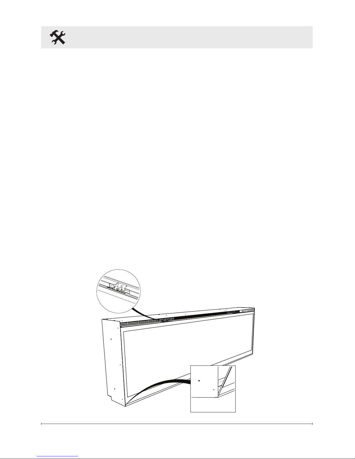
120V Installation - Plug Kit
WARNING: This heater is
not intended for use with an
extension cord. Plug the cord
directly into an ap propriate
wall receptacle.
To install a plug kit:
1. Locate the rear cover plate
about 12 in. (30.5 cm) from the
left side at the bottom. Remove
the 3 screws that hold the plate
(Figure 8).
2. Feed wire from plug kit into
opening and attached using the
using the 3 screws.
3. Connect the L1 wire from the
unit to the black wire of the plug
kit.
4. Connect the N wire from the
replace to the white wire from
the plug kit.
5. Connect ground wire from the
replace to the green wire from
the plug kit.
6. Ensure that all wire connections
are tight and that wires are
secured and do not protrude
past the ame panel, so as
not to be visible after nal
installation.
7. Continue to nal installation.
Figure 8

13
240V Installation
CAUTION: Use the appropriate
wire to meet local and national
electrical codes for rated power
consumption.
To 240V direct wire:
1. Connect the L1 wire from the
unit to the L1 wire from the
power supply with a wire nut.
2. Connect the L2 wire from the
unit to the L2 wire from the
power supply with a wire nut.
3. Connect the N wire from the
unit to the neutral wire from the
power supply.
4. Connect the G wire from the
unit to the ground wire from the
power supply with a wire nut
or attach the grounding wire
to the cover with the provided
grounding screw, by placing the
wire in-between screw and lock
washer and tighten (Figure 3).
5. Ensure that all wires are secure
and do not protrude past the
ame panel, so as not to be
visible after nal assembly.
6. Continue to the nal assembly
instructions.
Bathroom Use
If this unit is installed in a bathroom
it must be protected by a GFI
receptacle or circuit. If receptacle is
used it must be readily accessible.
To prevent electrical shock this
unit is an electrical appliance
that is NOT watertight and must
be installed as to prevent water
from entering unit. This must be
installed away from showers, tubs,
etc. Never locate replace where
it may fall into a bathtub or other
water container.
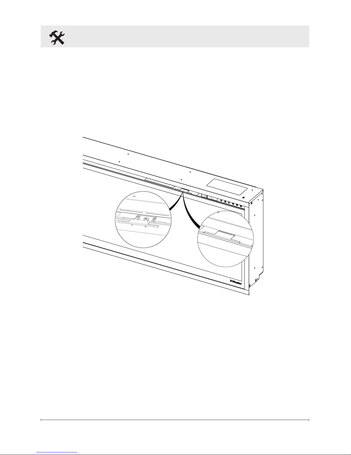
Final Assembly
1.
Locate and remove the screws
securing the partially reflective
glass bracket to the unit
(Figure 7), along the top of the
opening, and set bracket and
screws aside.
2. Remove the provided suction
cup from the inside cavity of the
unit.
3. Before installation ensure that
the front glass and the partially
reective glass are clean.
Particles can be removed by
dusting lightly with a clean dry
cloth. To remove ngerprints
Fireplace Installation (continued)
14 www.dimplex.com
or other marks, the glass
can be cleaned with a damp
cloth. Ensure that the glass
has completely dried before
installation.
4. Carefully secure the suction cup
to the partially reective glass,
reective side out, and place
into the openings on either side
of the unit.
5. Tip the glass into the unit and
using the removed screws
secure the glass into the unit
with the provided bracket
(Figure 9). Remove the
suction cup.
Fireplace Installation (continued)
6. Evenly space the large media
in the media tray along the back
of the media tray (for optimum
media effect), then carefully
pour and evenly distribute
the smaller media into the
Media Tray.
7. Carefully place the front glass
into the lip located at the bottom
of the opening of the rebox.
8. Tip the front glass into the
unit and secure using the
provided screws and Allen key
(Figure 10).
Figure 9
15
!
NOTE: Ensure that the suction
cup and Allen key are kept for
any future maintenance
or
service.
9. Install the provided screw
covers (Figure 10) by placing
tabs of the screw cover between
sides of front glass bracket.
Figure 10
Fireplace Installation (continued)
16 www.dimplex.com
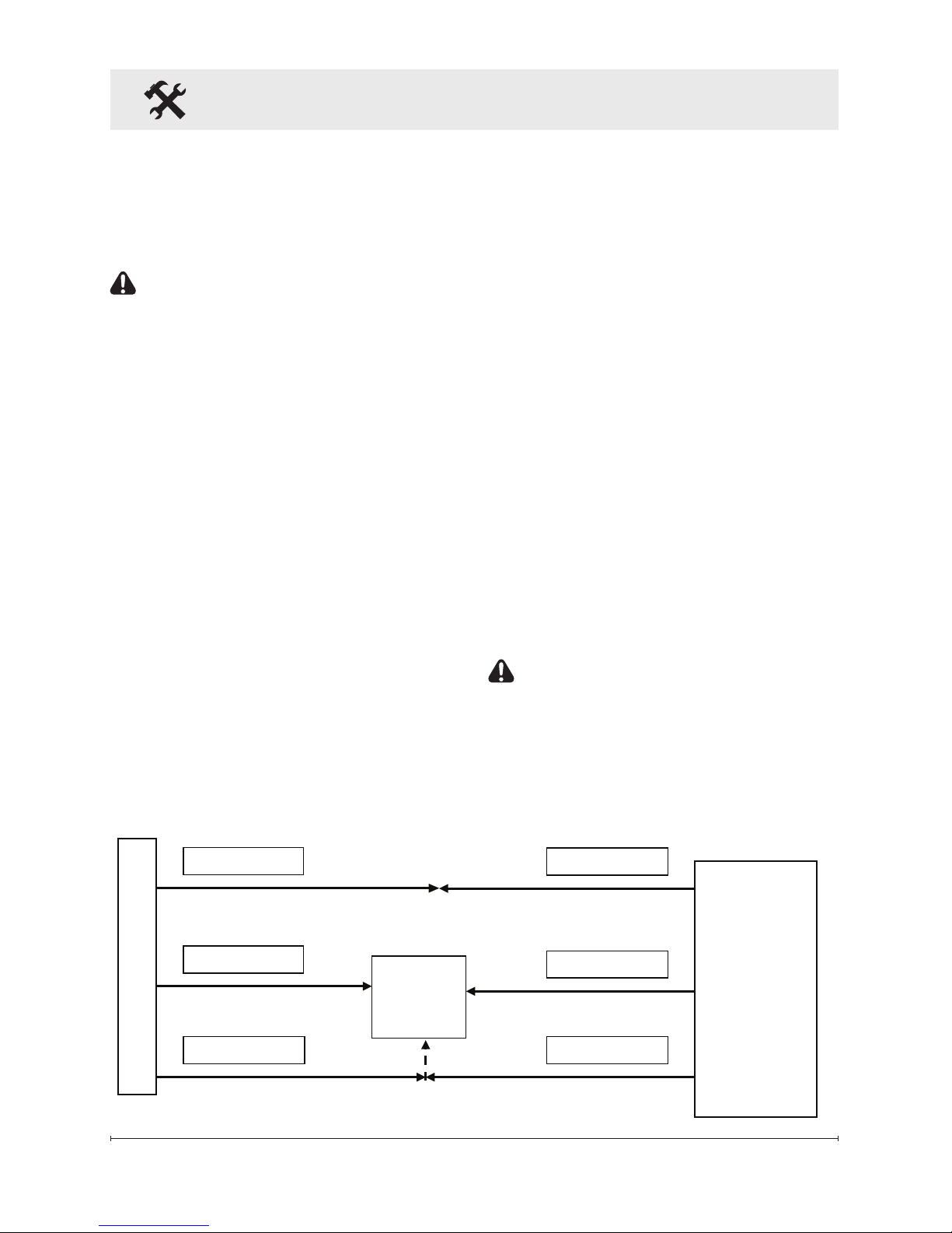
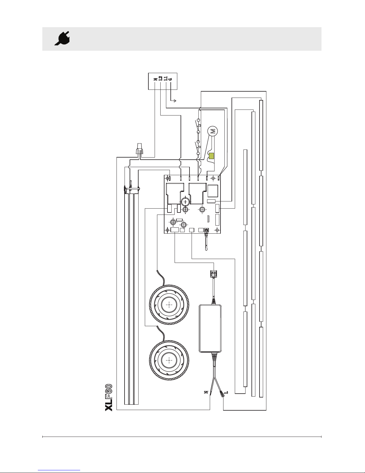
CUTOUTS
THERMAL
FLICKER MOTOR
FLAME LED ASSEMBLY
MEDIA LED ASSEMBLY
MEDIA LED ASSEMBLY
POWER ADAPTER
FAN
FAN
CERAMIC ELEMENT
MAIN CONTROL
BOARD
THERMISTOR
XLF60
M
Wiring Diagram
Figure 11
17
Operation
Remote Operation
The replace is supplied with an IR
multi-function remote control.
!
NOTE: To operate correctly, the
remote control must be pointed
towards the front of the unit.
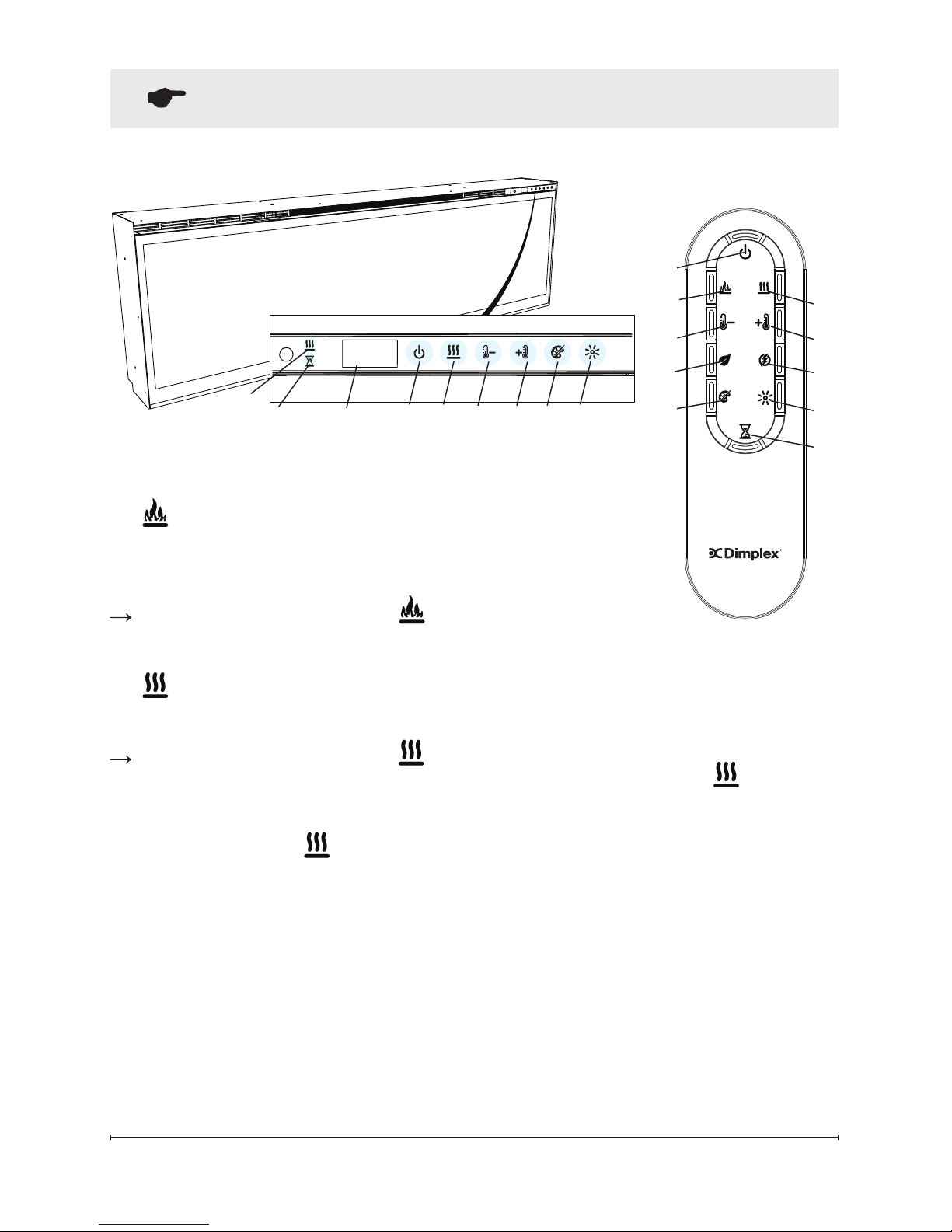
Controls
The unit can be controlled by
either the manual controls which
are located on the upper right of
the replace or the remote
(Figure 12 and 13).
A. Standby
Turns the unit On and Off.
Activated by pressing the
Standby button on the remote
or the unit.
• The unit will turn On with the
same functions that it was set
to when it was turned Off and
the intake temperature will be
indicated on the Display.
!
NOTE: When any button is
pressed on the unit the intake
temperature will be displayed on
the Display for 7 seconds.
General Operation
WARNING: This electric
firebox must be properly
installed before it is used.
This rebox operates with
Comfort$averTM technology,
which automatically adjusts the
fan speed and heater wattage to
safely and precisely match the
requirements of the room based on
the thermostat setting. The heater
operates such that once the room
reaches the set point, the fan and
heater will continuously run at a low
level, to maintain the desired room
temperature. If the temperature in
the room rises signicantly, (e.g.,
sun coming through a window or a
central furnace turns on) the heater
will turn off and periodically turn
back on to circulate the air around
the unit, until the room temperature
drops and requires the heater to be
constantly on again.
!
NOTE: The unit is designed so
that the fan will run continuously
while the heater is on.
!
NOTE: The unit retains heat
after shutdown. When the
heat is turned OFF, there is a
2-minute, built in cool down
period before the fan shuts off.
18 www.dimplex.com
Figure 12
A
C D E H
Display
Figure 13
A
D
B
C
E
G
J
F
I
H
I
Operation (continued)
B. Flame Effects
Turns the Flame Effect On
and Off.
Activated by pressing the
button on the remote.
C. Heat ON/OFF
Turns the heater On and Off.
Activated by pressing the
button on the remote or the
unit.
• Indicated by the
icon and the
set point temperature will ash
on the display, then the intake
temperature will be displayed
before turning off.
!
NOTE: After the heater is
switched off, there is a 2 minute
fan delay, where the fan will
continue running before turning
off.
!
NOTE: The unit can be
operated in Heat Only Mode.
When the unit is only running
with the heater, the icon will
continuously be displayed on
the Display.
!
NOTE: The heater may emit
a slight, harmless odor when
rst used. This odor is a normal
condition caused by initial
heating of internal heater parts
and will not occur again.
C
J
19
!
NOTE: Holding the and
the
buttons down for two
seconds, on the unit, will
change the temperature scale
from °C to °F, or vice versa.
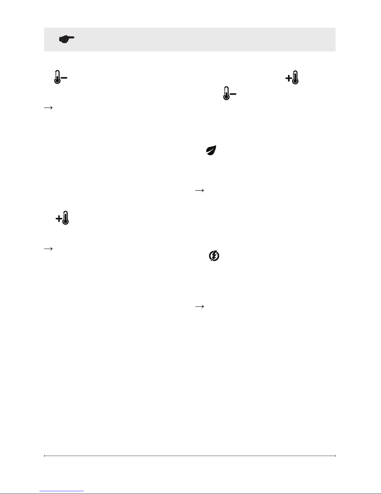
F.
Eco Operation
Runs the heater in a reduced
wattage range when activated.
Adjusted by pressing the
corresponding button on the
remote when the heater is on.
• Indicated by the Display and a
reduced fan speed.
G.
Heat Boost
Turns the Heater Boost On and
Off. Runs the unit at the full rated
wattage.
Activated and adjusted by
repeatedly pressing the
corresponding button on
the remote.
• Indicated by the heater running
at full heat, for a user set
amount of time, to quickly heat
up a cold room/space. The
Heat Boost can be set for a
maximum of 20 minutes, in
5 minute increments.
D
Temperature Down
Decreases the temperature setting.
Adjusted by repeatedly
pressing the corresponding
button on the remote.*
• Indicated by set point
temperature on the Display
decreasing and the speed of
the fan decreasing to reduce
the amount of heat being
projected into the room.
E. Temperature Up
Increases the temperature setting.
Adjusted by repeatedly
pressing the corresponding
button on the remote.*
• Indicated by the set point on
the Display increasing and the
speed of the fan increasing to
increase the amount of heat
being projected into the room.**
* The rst time the button
is pressed the current
temperature set point will be
displayed for 2 seconds.
** The temperature can be
adjusted from 5 °C to 37 °C
(41 °F to 99 °F).
Operation (continued)
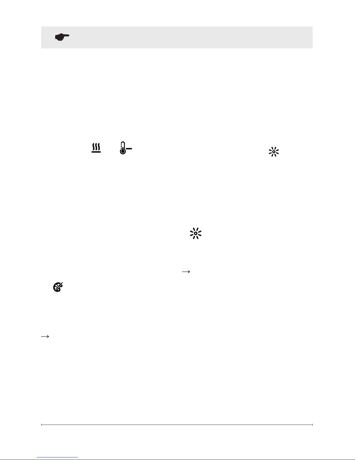
20 www.dimplex.com
• Cycles through the different
preset light settings of the
unit, this includes different
combinations of colors of the
ame base and media lighting.
!
NOTE: Two of the themes in
the cycle are a prism where the
unit cycles through a variety of
colors. Pressing the stops
the cycling and holds the unit on
the preferred color, indicated by
a solid circle. When the unit is
on prism, and is cycling through
the colors, a rotating circle will
be displayed.
I.
Brightness
Changes the Brightness of the
lights in the unit.
Adjusted by repeatedly pressing
the corresponding button on the
remote or the unit.
• Indicated by the second digit
on the Display changing to
show: "H" (high), and "L" (low).
Pressing the T- and Brightness
buttons at the same time and
holding them for 2 seconds will lock
(LOC will be displayed) or unlock
(U L will be displayed) the manual
controls on the replace.
Disable Heat
If desired, depending on the
season, the heater on the unit can
be disabled. The function of the
remaining controls will continue
to function as outlined in this
manual.
Pressing the and buttons
on the unit at the same time and
holding for 2 seconds will disable
and enable the heater.
!
NOTE: When the heater has
been disabled and any of the
heat related functions are used,
the Display will indicate "---".
If the Permanent Heat Disable
has been activated by removing
the jumper on the main PCB, the
display will indicate "H--".
H. Color Themes
Different presets of lighting color
combinations are available in
the unit.
Changed by repeatedly
pressing the corresponding
button on the remote or the
unit.
Operation (continued)
U
21
Operation (continued)
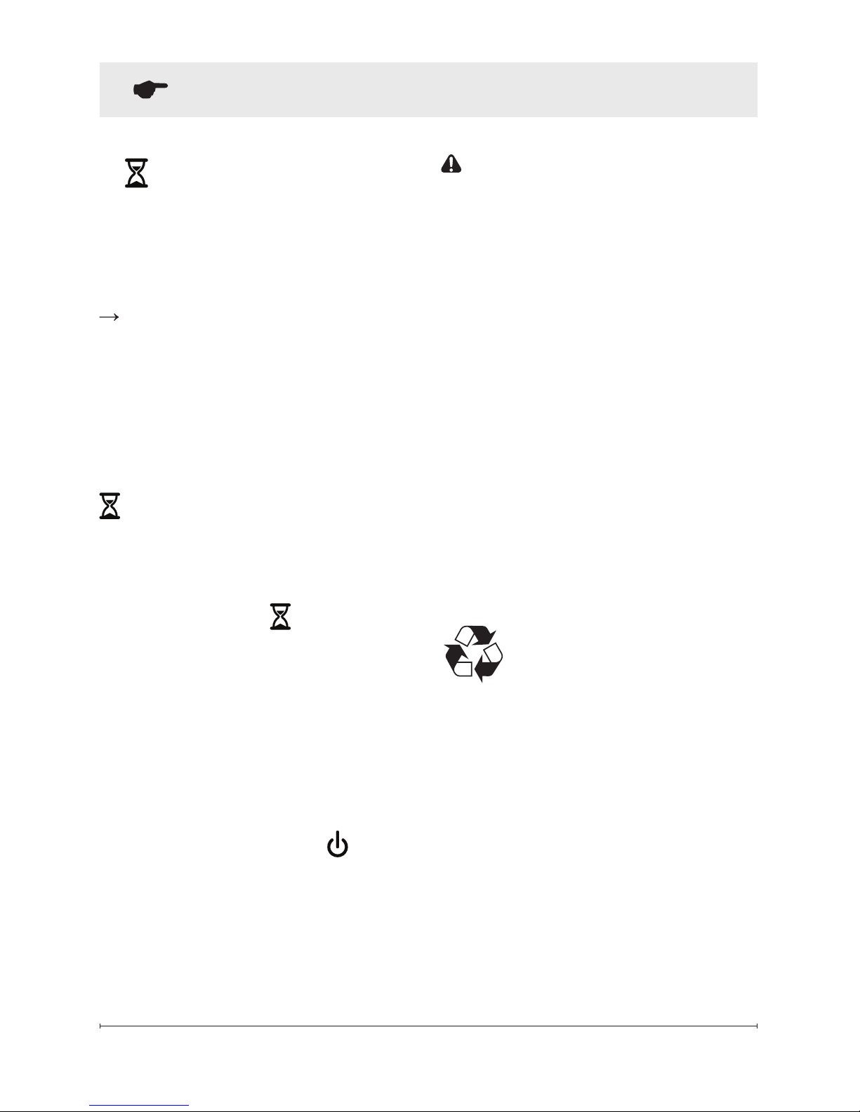
J. Sleep Timer
The Sleep Timer can be set to
automatically shut off the replace
after a preset time (from 30 minutes
to 8 hours).
To set the timer press the
timer button on the remote,
repeatedly, until the desired
time is displayed.
The Display will display the different
times as it is adjusted. Once the
timer has begun, pressing the
button will display the time
remaining before the unit turns Off.
!
NOTE: The Sleep Timer can
be cancelled at any time
by pressing the button
repeatedly until the sleep timer
displays nothing.
Resetting the Temperature
Cutoff Switch
Should the heater overheat, an
automatic cut out will turn the whole
unit off and it will not come back on
without being reset. If the button
on the unit is pressed, Er2 will be
displayed on the unit. It can be
reset by turning the unit off at the
main disconnect panel and waiting
5 minutes before turning the unit
back on.
CAUTION: If you need to
continuously reset the heater,
turn the unit off at the main
disconnect panel and call
technical support at 1-888346-7539.
Remote Control Battery
Replacement
To replace the battery:
1. Slide battery cover open on
the remote control.
2. Correctly install one 3 Volt
(CR2032 [longer life] or
CR2025) Battery in the battery
holder.
3. Close the battery cover.
Battery must be recycled
or disposed of properly.
Check with your Local
Authority or Retailer for recycling
advice in your area

22 www.dimplex.com
Maintenance
WARNING: Disconnect
power and allow heater to
cool before attempting any
maintenance or cleaning to
reduce the risk of re, electric
shock or damage to persons.
!
NOTE: The replace should
not be operated with an
accumulation of dust or dirt on
or in the unit, as this can cause
a build up of heat and eventual
damage. For this reason the
heater must be inspected
regularly, depending upon
conditions and at a minimum
yearly intervals.
Fireplace Surface Cleaning
Use only a damp cloth to clean
painted surfaces of the replace.
Do not use abrasive cleaners.
Servicing
Except for installation and cleaning
described in this manual, an
authorized service representative
should perform any other servicing.
Partially Reective Glass
Cleaning
The partially reective glass is
cleaned in the factory during
the assembly operation. During
shipment, installation, handling,
etc., the partially reective glass
may collect dust particles; these
can be removed by dusting lightly
with a clean dry cloth.
To remove ngerprints or other
marks, the partially reective glass
can be cleaned with a damp cloth.
The partially reective glass should
be completely dried with a lint
free cloth to prevent water spots.
To prevent scratching, do not use
abrasive cleaners.

23
Products to which this limited warranty
applies
This limited warranty applies to your newly
purchased Dimplex electric replace. This
limited warranty applies only to purchases
made in any province of Canada except
for Yukon Territory, Nunavut, or Northwest
Territories or in any of the 50 States of
the USA (and the District of Columbia)
except for Hawaii and Alaska. This limited
warranty applies to the original purchaser
of the product only and is not transferable.
Products excluded from this limited
warranty
Products purchased in Yukon Territory,
Nunavut, Northwest Territories, Hawaii,
or Alaska are not covered by this limited
warranty. Products purchased in these
States, provinces, or territories are sold
AS IS without warranty or condition of
any kind (including, without limitation,
any implied warranties or conditions of
merchantability or tness for a particular
purpose) and the entire risk of as to the
quality and performance of the products is
with the purchaser, and in the event of a
defect the purchaser assumes the entire
cost of all necessary servicing or repair.
What this limited warranty covers and for
how long
Products, other than replace surrounds
(mantels) and trims, covered by this
limited warranty have been tested and
inspected prior to shipment and, subject
to the provisions of this warranty, Dimplex
warrants such products to be free from
defects in material and workmanship for a
period of 2 years from the date of the rst
purchase of such products.
Dimplex replace surrounds (mantels)
and trims covered by this limited warranty
have been tested and inspected prior to
shipment and, subject to the provisions
of this warranty, Dimplex warrants such
products to be free from defects in
material and workmanship for a period of
1 year from the date of rst purchase of
such products.
The limited 2 year warranty period for
products other than replace surrounds
(mantels) and trims and the limited 1 year
warranty period for replace surrounds
(mantels) and trims also applies to any
implied warranties that may exist under
applicable law. Some jurisdictions do not
allow limitations on how long an implied
warranty lasts, so the above limitation may
not apply to the purchaser.
What this limited warranty does not cover
This limited warranty does not apply to
products that have been repaired (except
by Dimplex or its authorized service
representatives) or otherwise altered. This
limited warranty does further not apply
to defects resulting from misuse, abuse,
accident, neglect, incorrect installation,
improper maintenance or handling, or
operation with an incorrect power source.
What you must do to get service under
this limited warranty
Defects must be brought to the attention of
Dimplex Technical Service by contacting
Dimplex at 1-888-DIMPLEX
(1-888-346-7539), or 1367 Industrial
Road, Cambridge Ontario, Canada
N3H 4W3. Please have proof of purchase,
catalogue/model and serial numbers
available when calling. Limited warranty
service requires a proof of purchase of the
product.
What Dimplex will do in the event of a
defect
In the event a product or part covered
by this limited warranty is proven to be
defective in material or workmanship
during (i) the 2 year limited warranty
period for products other than replace
surrounds (mantels) and trims, and (ii)
the 1 year limited warranty period for
surrounds (mantels) and trims, you have
the following rights:
• Dimplex will in its sole discretion either
repair or replace such defective product
or part without charge. If Dimplex is
unable to repair or replace such product
Warranty

24 www.dimplex.com
or part, or if repair or replacement is
not commercially practicable or cannot
be timely made, Dimplex may, in lieu of
repair or replacement, choose to refund
the purchase price for such product or
part.
• Limited warranty service will be
performed solely by dealers or service
agents of Dimplex authorized to provide
limited warranty services.
• For products other than surrounds
(mantels) and trims, this 2 year limited
warranty entitles the purchaser to
on-site or in-home warranty services.
Accordingly, Dimplex will be responsible
for all labour and transportation
associated with repairing or replacing
the product or part except as follows:
(i) charges which may be levied for
travel costs incurred to travel to the
purchaser’s site where the product is
located if the purchaser’s site is beyond
30 miles (48 km) from the closest
service depot of Dimplex’s dealer or
service agent; and (ii) the purchaser is
solely responsible for providing clear
access to all serviceable parts of the
product.
• For surrounds (mantels) and trims,
this 1 year limited warranty does
not entitle the purchaser to on-site
or in-house warranty services. The
purchaser is responsible for removal
and transportation of the surrounds
(mantels) and trims (and any repaired
or replacement product or part) to
and from the authorized dealer’s or
service agent’s place of business. Onsite or in-home services for surrounds
(mantels) and trims may be performed
at the purchaser’s specic request
and expense at Dimplex’s then current
rates for such services. Dimplex will
not be responsible for, and this limited
warranty shall not include, any expense
incurred for installation or removal of the
surrounds (mantels) or trims or any part
thereof (or any replacement product
or part) including, without limitation, all
shipping costs and transportation costs
to and from the authorized dealer’s or
service agent’s place of business and
all labour costs. Such costs shall be the
purchaser’s responsibility.
What Dimplex and its dealers and service
agents are also not responsible for:
IN NO EVENT WILL DIMPLEX, OR ITS
DIRECTORS, OFFICERS, OR AGENTS,
BE LIABLE TO THE PURCHASER OR
ANY THIRD PARTY. WHETHER IN
CONTRACT, IN TORT, OR ON ANY
OTHER BASIS, FOR ANY INDIRECT,
SPECIAL, PUNITIVE, EXEMPLARY,
CONSEQUENTIAL, OR INCIDENTAL
LOSS, COST, OR DAMAGE ARISING
OUT OF OR IN CONNECTION WITH
THE SALE, MAINTENANCE, USE, OR
INABILITY TO USE THE PRODUCT,
EVEN IF DIMPLEX OR ITS DIRECTORS,
OFFICERS, OR AGENTS HAVE BEEN
ADVISED OF THE POSSIBILITY OF
SUCH LOSSES, COSTS OR DAMAGES,
OR IF SUCH LOSSES, COSTS, OR
DAMAGES ARE FORESEEABLE. IN
NO EVENT WILL DIMPLEX, OR ITS
OFFICERS, DIRECTORS, OR AGENTS
BE LIABLE FOR ANY DIRECT LOSSES,
COSTS, OR DAMAGES THAT EXCEED
THE PURCHASE PRICE OF THE
PRODUCT.
SOME JURISDICTIONS DO NOT ALLOW
THE EXCLUSION OR LIMITATION OF
INCIDENTAL OR CONSEQUENTIAL
DAMAGES, SO THE ABOVE LIMITATION
OR EXCLUSION MAY NOT APPLY TO
THE PURCHASER.
How State and Provincial law apply
This limited warranty gives you specic
legal rights, and you may also have other
rights which vary from jurisdiction to
jurisdiction. The provisions of the United
Nations Convention on Contracts for
the Sale of Goods shall not apply to this
limited warranty or the sale of products
covered by this limited warranty.
Warranty
 Loading...