

Page 1
Service Manual
Model UL Part Number
XLF50 6909630100
XLF74 6909690100
XLF100 6909700100
IMPORTANT SAFETY INFORMATION: Always read this manual rst before attempting to service this
replace. For your safety, always comply with all warnings and safety instructions contained in this
manual to prevent personal injury or property damage.
Dimplex North America Limited
1367 Industrial Road Cambridge ON Canada N3H 4W3
1-888-346-7539 www.dimplex.com
In keeping with our policy of continuous product development, we reserve the right to make changes without notice.
© 2016 Dimplex North America Limited
REV PCN DATE
00 - 21-JAN-16
7400940000R00
Page 2

TABLE OF CONTENTS
Operation ...........................................................3
Additional key Combinations ...........................................4
Maintenance .........................................................5
Exploded Parts Diagram - XLF50 ........................................6
Exploded Parts Diagram - XLF74 ........................................7
Exploded Parts Diagram - XLF100 .......................................8
Wiring DiagramS .....................................................9
Preparation for Service ...............................................10
Main Control Board Replacement ......................................11
LED Power Distributor Replacement (Only XLF74 & 100) ...................11
Power Supply Replacement ...........................................11
Capacative Controls and Display Replacement ...........................12
Media LED light Strips Replacement ....................................12
Flame LED Strips Replacement ........................................12
Flicker Assembly Replacement ........................................13
Thermistor Replacement .............................................13
Blower/Fan Replacement .............................................14
Troubleshooting Guide ...............................................15
Always use a qualied technician or service agency to repair this replace.
!
NOTE: Procedures and techniques that are considered important enough to emphasize.
CAUTION: Procedures and techniques which, if not carefully followed, will result in damage to the
equipment.
WARNING: Procedures and techniques which, if not carefully followed, will expose the user to the
risk of re, serious injury, or death.
2 www.dimplex.com
Page 3
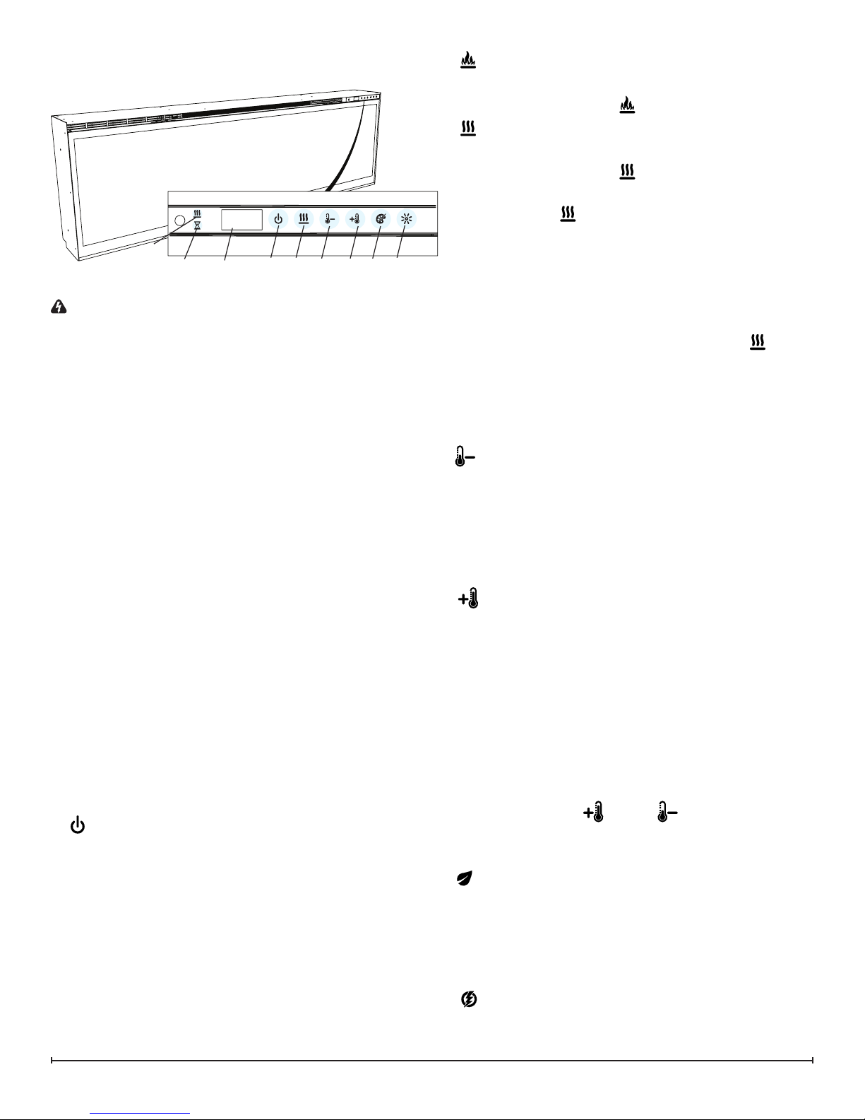
OPERATION
Figure 1
I
Display
J
General Operation
WARNING: This electric firebox must be properly in-
stalled before it is used.
This firebox operates with Comfort$averTM technology,
which automatically adjusts the fan speed and heater wattage to safely and precisely match the requirements of the
room based on the thermostat setting. The heater operates
such that once the room reaches the set point, the fan and
heater will continuously run at a low level, to maintain the
desired room temperature. If the temperature in the room
rises significantly, i.e. sun coming through a window or a
central furnace turns on, the heater will turn off and periodically turn back on to circulate the air around the unit, until
the room temperature drops and requires the heater to be
constantly on again.
!
NOTE: The unit is designed so that the fan will run con-
tinuously while the heater is on.
!
NOTE: The element retains heat after shutdown, there is
a built in cool down period of 2 minute before the fan shuts
off completely, when the heat function is turned Off.
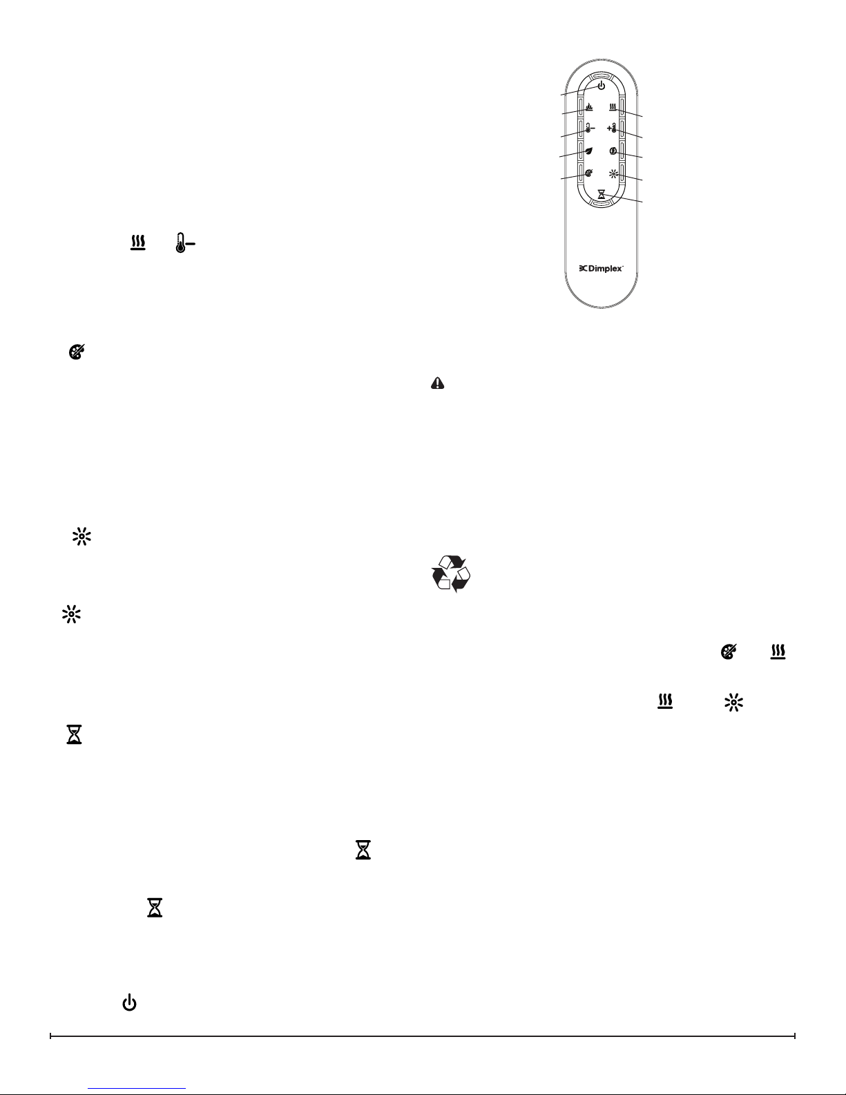
Remote Operation
The replace is supplied with an IR multi-function remote
control.
!
NOTE: To operate correctly, the remote control must be
pointed towards the front of the unit.
Controls
The unit can be controlled by either the manual controls
which are located on the upper right of the replace or the
remote (Figure 1 & 2).
A. Standby
Turns the unit On and Off.
→ Activated by pressing the Standby button on the remote
or the unit.
• The unit will turn On with the same functions that it was
set to when it was turned Off and the intake temperature
will be indicated on the Display.
!
NOTE: When any button is pressed on the unit the
intake temperature will be displayed on the Display for 7
seconds.
A
C D E F
G
B. Flame Effects
Turns the Flame Effect On and Off.
→ Activated by pressing the button on the remote.
C. Heat ON/OFF
Turns the heater On and Off.
→ Activated by pressing the button on the remote or the
unit.
• Indicated by the icon and the setpoint temperature will
ash on the display, then the intake temperature will be
displayed before turning off.
!
NOTE: After the heater is switched off, there is a 2
minute fan delay, where the fan will continue running before
turning off.
!
NOTE: The unit can be operated in Heat Only Mode.
When the unit is only running with the heater, the icon
will continuously be displayed on the Display.
!
NOTE: The heater may emit a slight, harmless odor
when rst used. This odor is a normal condition caused
by initial heating of internal heater parts and will not occur
again.
D Temperature Down
Decreases the temperature setting.
→ Adjusted by repeatedly pressing the corresponding but-
ton on the remote.*
• Indicated by setpoint temperature on the Display decreasing and the speed of the fan decreasing to reduce
the amount of heat being projected into the room.**
E. Temperature Up
Increases the temperature setting.
→ Adjusted by repeatedly pressing the corresponding but-
ton on the remote.*
• Indicated by the setpoint on the Display increasing and
the speed of the fan increasing to increase the amount of
heat being projected into the room.
* The rst time the button is pressed the current temper-
ature set point will be displayed for 2 seconds.
** The temperature can be adjusted from 5 °C to 37 °C (41
°F to 99 °F).
!
NOTE: Holding the and the buttons down for
two seconds, on the unit, will change the temperature scale
from °C to °F, or vice versa.
F. Eco Operation
Runs the heater in a reduced wattage range when activated.
→ Adjusted by pressing the corresponding button on the
remote when the heater is on.
• Indicated by the Display and a reduced fan speed.
G. Heat Boost
Turns the Heater Boost On and Off. Runs the unit at the full
rated wattage.
3
Page 4
→ Activated and adjusted by repeatedly pressing the cor-
responding button on the remote.
• Indicated by the heater running at full heat, for a user set
amount of time, to quickly heat up a cold room/space.
The Heat Boost can be set for a maximum of 20 minutes,
in 5 minute increments.
Disable Heat
If desired, depending on the season, the heater on the unit
can be disabled. The function of the remaining controls will
continue to function as outlined in this manual.
Pressing the and buttons on the unit at the same
time and holding for 2 seconds will disable and enable the
heater.
!
NOTE: When the heater has been disabled and any of
the heat related functions are used, the Display will indicate
“---”.
H. Color Themes
Different presets of lighting color combinations are available in the unit.
→ Changed by repeatedly pressing the corresponding but-
ton on the remote or the unit.
• Cycles through the different preset light settings of the
unit, this includes different combinations of colors of the
ame base and media lighting.
!
NOTE: Two of the themes in the cycle are a prism
where the unit cycles through a variety of colors. Pressing
the stops the cycling and holds the unit on the preferred
color, indicated by a solid circle. When the unit is on prism,
and is cycling through the colors, a rotating circle will be
displayed.
Figure 2
A
B
D
F
H
displayed on the unit. It can be reset by turning the unit off
at the main disconnect panel and waiting 5 minutes before
turning the unit back on.
CAUTION: If you need to continuously reset the heater,
turn the unit off at the main disconnect panel and call technical support at 1-888-346-7539.
C
E
G
I
J
Remote Control Battery Replacement
To replace the Battery:
1. Slide battery cover open on the remote control.
2. Correctly install one 3 Volt (CR2032 [longer life] or
CR2025) Battery in the battery holder.
3. Close the battery cover.
Battery must be recycled or disposed of properly.
Check with your Local Authority or Retailer for recycling advice in your area
I.
Brightness
Changes the Brightness of the lights in the unit.
→ Adjusted by repeatedly pressing the corresponding but-
ton on the remote or the unit.
• Indicated by the second digit on the Display changing to
show: “H” (high), and “L” (low).
J. Sleep Timer
The Sleep Timer can be set to automatically shut off the
replace after a preset time (from 30 minutes to 8 hours).
→ To set the timer press the timer button on the remote,
repeatedly, until the desired time is displayed.
• The Display will display the different times as it is adjusted. Once the timer has begun, pressing the button
will display the time remaining before the unit turns Off.
!
NOTE: The Sleep Timer can be cancelled at any time
by pressing the button repeatedly until the sleep timer
displays nothing.
Resetting the Temperature Cutoff Switch
Should the heater overheat, an automatic cut out will turn
the whole unit off and it will not come back on without being
reset. If the button on the unit is pressed, Er2 will be
ADDITIONAL KEY COMBINATIONS
Software Revision Display - On the unit, hold and
to display the software revision of the unit.
Factory Reset - On the unit, hold the and the
the display shows “ooo”
, until
4 www.dimplex.com
Page 5

MAINTENANCE
WARNING: Disconnect power and allow heater to cool
before attempting any maintenance or cleaning to reduce
the risk of re, electric shock or damage to persons.
!
NOTE: The replace should not be operated with an
accumulation of dust or dirt on or in the unit, as this can
cause a build up of heat and eventual damage. For this
reason the heater must be inspected regularly, depending
upon conditions and at least at yearly intervals.
Partially Reective Glass Cleaning
The partially reective glass is cleaned in the factory during the assembly operation. During shipment, installation,
handling, etc., the partially reective glass may collect dust
particles; these can be removed by dusting lightly with a
clean dry cloth.
To remove ngerprints or other marks, the partially reective glass can be cleaned with a damp cloth. The partially
reective glass should be completely dried with a lint free
cloth to prevent water spots. To prevent scratching, do not
use abrasive cleaners.
Fireplace Surface Cleaning
Use only a damp cloth to clean painted surfaces of the
replace. Do not use abrasive cleaners.
Servicing
Except for installation and cleaning described in this manual, an authorized service representative should perform any
other servicing.
5
Page 6

EXPLODED PARTS DIAGRAM - XLF50
1
4
10
12
11
Replacement Parts List - XLF50
3
5
9
16
15
7
8
13
14
2
1. Heater Assembly (with cutouts) .....2203720100RP
2. Remote Control ..................3001250100RP
3. Main Control Board ...............3001650100RP
4. Capacative Controls and Display ....3001680100RP
5. Power Supply ...................2100250500RP
6. Thermistor ......................3001560500RP
7. Partially Reective Glass ..........5902890100RP
8. Front Glass .....................5902900100RP
9. Flicker Motor ....................2000500900RP
10. Flicker Assembly ................5902920100RP
11. 6-Light LED Flame Assembly .......3001670100RP
6 www.dimplex.com
12. 8-Light LED Flame Assembly .......3001670200RP
13. 4-Light RGB LED Assembly (2) .....3001570400RP
14. Media Tray .....................5902910100RP
15. 6-Light Coloured Media LED Assembly ....3001570100RP
16. 8-Light Coloured Media LED Assembly (2) .3001570300RP
17. Hardware Kit ....................9600360100RP
18. Large Acrylic Media ...............1400130200RP
19. Medium Acrylic Media .............1400150100RP
Accessories
River Rocks .............................DFS1314
Driftwood Accessory Kit ................LF50DWS-KIT
Page 7

EXPLODED PARTS DIAGRAM - XLF74
6
1
4
3
19
LED Conguration
Flame LED’s (white)
Flame Base (colour)
Media (colour)
2
Replacement Parts List - XLF74
1. Heater Assembly (with cutouts) .....2203720100RP
2. Remote Control ..................3001250100RP
3. Main Control Board ...............3001650100RP
4. Capacative Controls and Display ....3001680100RP
5. Power Supply (2) ................2100250600RP
6. Thermistor ......................3001560700RP
7. Partially Reective Glass ..........5902890200RP
8. Front Glass .....................5902940100RP
9. Flicker Motor ....................2000480200RP
10. Flicker Assembly ................5902920200RP
11. 6-Light LED Flame Assembly .......3001670100RP
10
5
13
9
7
8
12
15
15 15
11
14
12
15
15
12. 8-Light LED Flame Assembly (2) ....3001670200RP
13. Media Tray .....................5902910200RP
14. 6-Light Coloured Media LED Assembly ....3001570100RP
15. 8-Light Coloured Media LED Assembly (5) .3001570300RP
16. Hardware Kit ....................9600360100RP
17. Large Acrylic Media ...............1400130300RP
18. Medium Acrylic Media (2) ..........1400150100RP
19. LED Power Distributor ............3001720100RP
Accessories
River Rocks .............................DFS1314
Driftwood Accessory Kit ................LF74DWS-KIT
7
Page 8

EXPLODED PARTS DIAGRAM - XLF100
6
1
5b
4
3
18
LED Conguration
Flame LED’s (white)
Flame Base (colour)
Media (colour)
2
Replacement Parts List - XLF100
1. Heater Assembly (with cutouts) ......2203720100RP
2. Remote Control ...................3001250100RP
3. Main Control Board ................3001650100RP
4. Capacative Controls and Display .....3001680100RP
5. Power Supply a) 5 Amp ............2100250500RP
b) 3 Amp .............2100250600RP
6. Thermistor .......................3001560700RP
7. Partially Reective Glass ...........5902890300RP
8. Front Glass ......................5902940200RP
9. Flicker Motor .....................2000480200RP
10. Flicker Assembly .................5902920300RP
10
5a
12
7
8
11
13
14
11
13
14
11
13
14
11
13
11
13
14
11. 6-Light LED Flame Assembly (5) .....3001670100RP
12. Media Tray ......................5902910300RP
13. 6-Light Coloured Media LED Assembly (5) . 3001570100RP
14. 8-Light Coloured Media LED Assembly (4) . 3001570300RP
15. Hardware Kit .....................9600350100RP
16. Large Acrylic Media ................1400130200RP
17. Medium Acrylic Media (2) ...........1400150100RP
18. LED Power Distributor ............3001720100RP
Accessories
Driftwood Accessory Kit (2) .............LF50DWS-KIT
9
8 www.dimplex.com
Page 9

WIRING DIAGRAMS
XLF50
CERAMIC ELEMENT
MAIN CONTROL
BOARD
FAN
XLF74, XLF100
FAN
POWER ADAPTER
POWER ADAPTER
FAN
FLAME LED ASSEMBLY
CERAMIC ELEMENT
FAN
THERMISTOR
THERMISTOR
MAIN CONTROL
BOARD
THERMAL
CUTOUTS
FLICKER MOTOR
MEDIA LED ASSEMBLY
MEDIA LED ASSEMBLY
THERMAL
CUTOUTS
FLICKER MOTOR
M
M
POWER ADAPTER
RELAY BOARD
FLAME LED ASSEMBLY
MEDIA LED ASSEMBLY
MEDIA LED ASSEMBLY
9
Page 10

Figure 3
16.49 in
419 mm
XLF50 50.31 in [1278 mm]
XLF74 74.31 in [1887 mm]
XLF100 100.31 in [2548 mm]
15.00 in.
381 mm
15.82 in.
402 mm
XLF50 51.41 in [1306 mm]
XLF74 75.41 in [1941 mm]
XLF100 101.41 in [2576 mm]
PREPARATION FOR SERVICE
!
NOTE: All components are replaceable from the front
of the replace while the unit is mounted in the wall.
Tools Required: Philips head screwdriver
WARNING: Disconnect power before attempting any
maintenance or cleaning to reduce the risk of electric
shock or damage to persons.
CAUTION: If unit was operating prior to servicing allow
at least 10 minutes for lights and heating elements to cool
off to avoid accidental burning of skin.
!
NOTE: All instructions are created for replacement
of the XLF50 components and as a result the number of
screws may differ for the XLF74 and XLF100.
1. Turn the breaker off at the electrical panel.
2. Remove the front glass assembly by removing the 2
screws (1 on the left and 1 on the right side, located
just inside the top front vent opening). These screws
secure the front glass panel to the inside of the replace. (Figure 4)
3. Lift the front glass assembly out of the unit and care-
fully place the glass assembly aside in a safe location.
4. Remove the decorative acrylic ember-bed pieces from
the media tray, which lies along the bottom of the inter-
ior Partially Reective Glass. A medium sized container
such as a bucket or a box will be needed to keep the
acrylic ember-bed pieces together.
5. Attach the suction cup to the partially reective glass to
assist with removat.
6. Remove the Partially Reective Glass by removing the
12 screws from the glass retaining bracket, starting on
either end and working your way to the middle, along
the top of the opening, ensuring that neither the bracket
Figure 4
Figure 5
4.34 in.
110 mm
5.79 in.
147 mm
10 www.dimplex.com
Page 11

or the partially reective glass falls out of the unit. (Figure 5)
7. Gently lift the partially reective glass out of the unit
and set it aside in a safe place.
CAUTION: Partially Reective Glass is not tempered.
Do not bump or drop the Partially Reective Glass to avoid
breakage and personal injury.
8. Proceed to the instructions within this manual relating
to the repair being performed - see Table of Contents
for page number.
MAIN CONTROL BOARD
REPLACEMENT
WARNING: Disconnect power before attempting any
maintenance or cleaning to reduce the risk of electric
shock or damage to persons.
CAUTION: If unit was operating prior to servicing allow
at least 10 minutes for lights and heating elements to cool
off to avoid accidental burning of skin.
Tools required: Phillips head screwdriver
CAUTION: Follow “Preparation for Service” instructions
before proceeding.
1. Locate the main control board. (Figure 6)
2. Transfer the connections from the old board to the new
board.
3. Remove the board, by removing the screw on each
corner.
4. Install the new board onto the unit.
5. Ensure that all cords are replaced in the same manner
as prior to the service.
6. Reassemble in the reverse order as above.
Figure 6
XLF50
XLF74/100
Capacative Controls
and Display
Main Control
Board
LED POWER DISTRIBUTOR
REPLACEMENT (ONLY XLF74 & 100)
WARNING: Disconnect power before attempting any
maintenance or cleaning to reduce the risk of electric
shock or damage to persons.
CAUTION: If unit was operating prior to servicing allow
at least 10 minutes for lights and heating elements to cool
off to avoid accidental burning of skin.
Tools required: Phillips head screwdriver
CAUTION: Follow “Preparation for Service” instructions
before proceeding.
1. Locate the power distributor. (Figure 6)
2. Transfer the connections from the old board to the new
board.
3. Remove the board, by removing the screw on each
end.
4. Install the new board onto the unit.
5. Ensure that all cords are replaced in the same manner
as prior to the service.
6. Reassemble in the reverse order as above.
Power Supply
LED Power
Distributor
Flame Panel
Flicker Motor
POWER SUPPLY REPLACEMENT
WARNING: Disconnect power before attempting any
maintenance or cleaning to reduce the risk of electric
shock or damage to persons.
CAUTION: If unit was operating prior to servicing allow
at least 10 minutes for lights and heating elements to cool
off to avoid accidental burning of skin.
Tools required: Phillips head screwdriver
CAUTION: Follow “Preparation for Service” instructions
before proceeding.
1. Locate the power supply. (Figure 6)
11
Page 12

2. Remove the screws that secure the holding bracket
and power supply to the unit.
3. Trace the wires to the main control board and disconnect.
4. Run the wiring from the new power supply to the main
control board.
5. Reinstall the bracket.
6. Ensure that all cords are replaced in the same manner
as prior to the service.
7. Reassemble in the reverse order as above.
CAPACATIVE CONTROLS AND
DISPLAY REPLACEMENT
WARNING: Disconnect power before attempting any
maintenance or cleaning to reduce the risk of electric
shock or damage to persons.
CAUTION: If unit was operating prior to servicing allow
at least 10 minutes for lights and heating elements to cool
off to avoid accidental burning of skin.
Tools required: Phillips head screwdriver
CAUTION: Follow “Preparation for Service” instructions
before proceeding.
1. In the upper right hand corner of the unit, above the
main control board, locate the controls and display
assembly and remove the 2 securing screws. (Figure 6)
1. Gently remove the assembly from the unit by pulling it
forward. (Figure 12)
2. Disconnect the wire from the old assembly and install it
on the new assembly.
3. Reinstall the new board onto the unit.
4. Ensure that all cords are replaced in the same manner
as prior to the service.
5. Reassemble in the reverse order as above.
MEDIA LED LIGHT STRIPS
REPLACEMENT
WARNING: Disconnect power before attempting any
maintenance or cleaning to reduce the risk of electric
shock or damage to persons.
CAUTION: If unit was operating prior to servicing allow
Figure 7
Media Tray screws (4)
Front
Panel
at least 10 minutes for lights and heating elements to cool
off to avoid accidental burning of skin.
Tools required: Phillips head screwdriver
Needle nose pliers
CAUTION: Follow “Preparation for Service” instructions
before proceeding.
1. Remove the plastic media tray by removing the 4
screws: 2 on the left and 2 on the right of the tray.
(Figure 7)
2. Lift the plastic media tray out of the unit.
3. Remove the front panel by removing the 6 screws: 3 on
the left and 3 on the right of the tray.
4. Locate the LED assembly that needs to be removed.
5. Disconnect the wiring connections at either end.
6. Remove the assembly by pinching the plastic mounting
tabs with needle nose pliers and lifting off.
7. Install the new assembly onto the unit and secure the
LED strip to the unit.
8. Reattach the wire connections.
9. Ensure that all cords are replaced in the same manner
as prior to the service.
10. Reassemble in the reverse order as above.
FLAME LED STRIPS REPLACEMENT
WARNING: Disconnect power before attempting any
maintenance or cleaning to reduce the risk of electric
shock or damage to persons.
CAUTION: If unit was operating prior to servicing allow
at least 10 minutes for lights and heating elements to cool
off to avoid accidental burning of skin.
Tools required: Phillips head screwdriver
Wire snips
CAUTION: Follow “Preparation for Service” instructions
before proceeding.
1. Remove the plastic media tray by removing the 4
screws: 2 on the left and 2 on the right of the tray.
(Figure 7)
2. Lift the plastic media tray out of the unit.
3. Remove the front panel by removing the 6 screws: 3 on
the left and 3 on the right of the tray.
4. Remove the 17 screws along the top of the ame panel
and gently remove. (Figure 6)
5. Locate the LED assembly that needs to be removed.
6. Disconnect the wiring connections at either end.
7. Remove the assembly by pinching the plastic mounting
tabs with needle nose pliers and lifting off.
8. Install the new assembly onto the unit and secure the
LED strip to the unit.
9. Reattach the wire connections.
10. Ensure that all cords are replaced in the same manner
as prior to the service.
11. Reassemble in the reverse order as above.
12 www.dimplex.com
Page 13

FLICKER ASSEMBLY REPLACEMENT
WARNING: Disconnect power before attempting any
maintenance or cleaning to reduce the risk of electric
shock or damage to persons.
CAUTION: If unit was operating prior to servicing allow
at least 10 minutes for lights and heating elements to cool
off to avoid accidental burning of skin.
Tools required: Phillips head screwdriver
Wire snips
CAUTION: Follow “Preparation for Service” instructions
before proceeding.
1. Remove the plastic media tray by removing the 4
screws: 2 on the left and 2 on the right of the tray.
(Figure 7)
2. Lift the plastic media tray out of the unit.
3. Remove the front panel by removing the 6 screws: 3 on
the left and 3 on the right of the tray.
4. Remove the 17 screws along the top of the ame panel
and gently remove. (Figure 6)
5. Gently pull the motor away from the icker rod.
CAUTION: When removing and replacing the icker motor try to keep any slight bending of the icker rod minimal
so as to not damage it. If icker rod is damaged, it should
be replaced to ensure proper operation.
6. Ensure that all cords are replaced in the same manner
as prior to the service.
7. Reassemble in the reverse order as above.
FLICKER MOTOR REPLACEMENT
WARNING: Disconnect power before attempting any
maintenance or cleaning to reduce the risk of electric
shock or damage to persons.
CAUTION: If unit was operating prior to servicing allow
at least 10 minutes for lights and heating elements to cool
off to avoid accidental burning of skin.
Tools required: Phillips head screwdriver
Short handled Phillips head screwdriver
CAUTION: Follow “Preparation for Service” instructions
before proceeding.
1. Remove the plastic media tray by removing the 4
screws: 2 on the left and 2 on the right of the tray.
(Figure 7)
2. Lift the plastic media tray out of the unit.
3. Remove the front panel by removing the 6 screws: 3 on
the left and 3 on the right of the tray.
4. Remove the two access covers located on the bottom
right hand side by removing the screws securing them
to the unit.
5. Remove the icker motor mounting bracket from the
unit.
6. Remove the 2 screws holding the icker motor to the
mounting bracket. Gently pull the motor away from the
icker rod.
7. Remove the 2 screws holding the icker motor to the
mounting bracket. Gently pull the motor away from the
icker rod.
8. Trace the wiring up to the main control board and replace with new wires.
9. Properly orient the new icker motor onto the motor
bracket and re-attach with the 2 mounting screws.
CAUTION: When removing and replacing the icker mo-
tor try to keep any slight bending of the icker rod minimal
so as to not damage it. If icker rod is damaged, it should
be replaced to ensure proper operation.
10. Reassemble in the reverse order as above.
THERMISTOR REPLACEMENT
WARNING: Disconnect power before attempting any
maintenance or cleaning to reduce the risk of electric
shock or damage to persons.
CAUTION: If unit was operating prior to servicing allow
at least 10 minutes for lights and heating elements to cool
off to avoid accidental burning of skin.
Tools required: Phillips head screwdriver
CAUTION: Follow “Preparation for Service” instructions
before proceeding.
1. Locate the thermistor attached to the bracket in the
upper left hand side of the unit. (Figure 12)
2. Remove the thermistor by cutting the tie wrap securing
it to the standoff.
3. Follow the cable back to the main control board and
disconnect the old thermistor and connect the new
cable.
4. Rerun the thermistor back to the brack ensuring that
the wiring is replaced in the original locations.
5. Ensure that all cords are replaced in the same manner
as prior to the service.
6. Reassemble in the reverse order as above.
Figure 8
Access
Covers
13
Page 14

BLOWER/FAN REPLACEMENT
WARNING: Disconnect power before attempting any
maintenance or cleaning to reduce the risk of electric
shock or damage to persons.
CAUTION: If unit was operating prior to servicing allow
at least 10 minutes for lights and heating elements to cool
off to avoid accidental burning of skin.
Tools required: Phillips head screwdriver.
Needle nosed pliers.
CAUTION: Follow “Preparation for Service” instructions
before proceeding.
1. Remove the 10 screws that secure the heater assem-
bly retaining bracket to the unit. Remove the bracket
and set aside.
2. Locate and remove the 4 screws that secure the as-
sembly to the unit.
CAUTION: When removing the blower assembly mounting screws support the assembly to prevent any damage to
the unit.
3. Disconnect the wiring connections noting their original
locations.
!
NOTE: Using a at head screwdriver gently pry be-
tween the end of the connectors and the blower/fan to
release the wires.
4. Properly orient the new blower/fan assembly and con-
nect all of the wiring connections.
5. Reassemble in the reverse order as above.
Figure 9
Mounting Screws
Retaining
Bracket
14 www.dimplex.com
Page 15

TROUBLESHOOTING GUIDE
PROBLEM CAUSE SOLUTION
General
Circuit breaker trips or fuse blows
when unit is turned on
Lights dim in room while the unit
is on
Appearance
Fireplace does not turn on with the
capacative controls
Fireplace does not turn on with the
Remote Control
Flame Frozen Loose wiring Check wiring connections
Flame is not visible Loose wiring Check wiring connections
Flame Shudder Defective Flicker Motor Replace Flicker Motor
Media bed does not light up Loose wiring Check wiring connections
Media bed lighting comes on by
itself
Short in unit wiring. Trace wiring in unit.
Improper circuit current rating Additional appliances may exceed the current rating
of the circuit breaker or fuse. Plug unit into another
outlet or install unit on a dedicated 15 amp circuit.
Unit is drawing close to circuit current
rating
Improper operation Refer to Operation Section
No incoming voltage from the electrical
wall socket
Loose wiring Check wiring connections
Defective capacative control assembly Replace the capacative control assembly
Defective main control board Replace the main control board
Improper operation Refer to Operation Section
The batteries in the remote control are
dead.
Defective remote control Replace the remote control
Defective capacative control assembly Replace the capacative control assembly
Defective main control board Replace the main control board
Defective Flicker Motor Replace Flicker Motor
Defective main control board Replace the main control board
Flame LED light assembly is not working Replace ame LED light assembly
Relay board is defective Replace relay board
Defective power supply Replace power supply
Defective LED power distributor (XLF74 &
XLF100 only)
Defective main control board Replace the main control board
Media LED light assembly is not working Replace media LED light assembly
Defective main control board Replace the main control board
Defective main control board Replace the main control board
Move the unit to another outlet or install unit on a
dedicated 15 amp circuit
Check Fuse/Breaker Panel
Install new battery into the remote control.
Replace LED power distributor
15
Page 16

PROBLEM CAUSE SOLUTION
Heater
Heater is not turning on, but ame
effect is still functioning
Heater is turning off after a couple
of minutes of operation
Heater emits an odor Normal Operation Normal operation is when the heater emits an odor
Heater fan turns On but heater
lacks heat
Heating element is glowing red Normal Operation Small glowing sections of the element are consid-
Heater fan runs continuously Loose wiring Trace wiring in unit
Noise
Excessive noise with the heater on Dirty Heater Assembly Ensure that exterior intake louvers and rebox cavity
Grinding or excessive noise with
the heater off
Improper operation Refer to Operation Section
Loose wiring Trace wiring in unit
Defective main control board Replace the main control board
Defective Heating Element Replace Heating Element
Improper operation Refer to Operation Section
Build up of dirt/dust in Heater Assembly Ensure that exterior intake louvers and rebox cavity
are free of dirt/dust.
Defective Blower/Fan Replace Blower/Fan
Defective Heating Element Replace Heating Element
for a brief period after the heater is initially turned on.
The heater is burning off any dust accumulated during manufacturing or operation.
Defective Heating Element Replace Heating Element
Improper operation Refer to Operation Section
Heater turned off too early If the heater is turned off before it has run for 2 min-
utes the fan will continue to run for 2 minutes to fully
cirulate air
Loose wiring Trace wiring in unit
Defective Heating Element Replace Heating Element
ered normal.
Defective Heating Element If larger glowing sections are causing the heater to
trip the thermal cutout, unplug unit, discontinue use
and replace the heating element
Defective main control board Replace the main control board
Defective Blower/Fan Replace Blower/Fan
are free of dirt/dust.
Defective Blower/Fan Replace Blower/Fan
Flicker rod hitting or rubbing against inter-
nal components
Defective Flicker Motor Replace Flicker Motor
Ensure rod is straight and mounted properly in the
bracket, spinning freely away from other components.
Replace if necessary.
16 www.dimplex.com
 Loading...