

Page 1
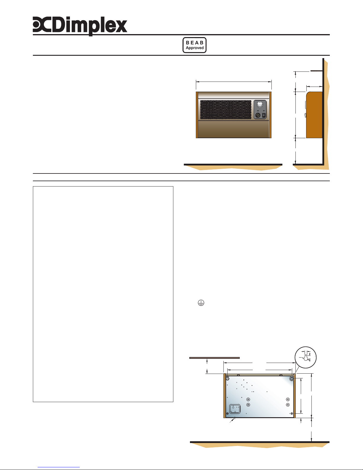
150mm min.
120mm
shelf
571mm
350mm min.
350mm
13 : 17
THESE INSTRUCTIONS SHOULD BE READ CAREFULL Y AND RET AINED FOR FUTURE REFERENCE
Important Safety Advice
WARNING – THIS APPLIANCE MUST NOT BE USED IN A
BATHROOM.
WARNING – DO NOT USE THIS HEATER IN THE IMMEDIATE
SURROUNDINGS OF A BATH, A SHOWER OR A SWIMMING POOL.
WARNING – THIS HEA TER MUST NOT BE LOCA TED IMMEDIA TEL Y
ABOVE OR BELOW A FIXED SOCKET OUTLET.
DO NOT USE THE HEATER UNTIL IT IS WALL MOUNTED
CORRECTL Y.
The heater carries a warning ‘Do Not Cover’ to alert the user
to the risk of overheating that exists if the heater is
accidentally covered.
Keep combustible materials such as drapes and other
furnishings clear from the front of the heater. Do not use
heater to dry your laundry.
NEVER cover or obstruct in any way the air inlet slots at the
front of the heater or the heat outlet slots in the base of the
heater.
This appliance is not intended for use by children or other
persons without assistance or supervision if their physical,
sensory or mental capabilities prevent them from using it
safely. Children should be supervised to ensure that they
do not play with the appliance.
If young children, the aged, or infirm are likely to be left in
the vicinity of the heater, we advise that adequate
precautions should be taken. We recommend that a guard
be fitted to ensure contact with the heater is avoided and
objects cannot be inserted into the product.
WARNING: In order to avoid a hazard due to inadvertent
resetting of the thermal cut-out, this appliance must not be
supplied through an external switching device, such as a
timer, or connected to a circuit that is regularly switched on
and off by the utility.Do not use where excessive dust or
moisture is present.
Do not use where excessive dust or moisture is present.
For further information, please contact our guard supplier
direct on Tel. No. 01603 667957, or in the case of difficulty or
for further advice contact our Customer Helpline.
Installation
Before undertaking installation work, ensure the electricity
supply is disconnected from any relevant fixed wiring.
Supply cable is not provided with this appliance, and a competent
electrician should therefore install it.
The appliance must be fitted horizontally with the cable or conduit entry
at bottom right. It should be mounted such that the underside is at least
350mm above the floor and the top of the heater is 150mm below any
Dimplex Wall-mounted Fan Convector
Model(s) : WFE 3TNB and WFE 3TNS
Installation and Operating Instructions
08/18748/6 (UK) Issue 6
Model(s) Specification
WFE 3TNB 3kW, Switch, Thermostat & 7 Day Timer - Black
WFE 3TNS 3kW, Switch, Thermostat & 7 Day Timer - Silver
Dimensions
(millimetres)
Fig. 1
overhanging shelf or obstruction.
This heater must be used on an A.C.~ supply only and the voltage
marked on the heater must correspond to the supply voltage.
To comply with the I.E.E. Wiring Regulations, the appliance must be
earthed; the supply circuit must be adequate for the input of the appliance,
and the circuit protected by a suitable 13A fuse. A suitable termination to
the fixed wiring of the premises must be provided adjacent to the final
position of the appliance. In this instance, such a termination can be a
double-pole switch with a contact separation of at least 3mm in all
poles.
The heater must not be located immediately below a fixed
socket-outlet.
Electrical
WARNING : THIS APPLIANCE MUST BE EARTHED.
After ensuring the electricity supply is not live, electrical connections
can be made, either to an adjacent double-pole switch having a contact
separation of at least 3mm in all poles or to a plug-top for use in a
standard 13A socket.
If the latter: Connect Green and Yellow wire to plug terminal marked ‘E’
or Green or Green and Yellow. Connect Blue wire to plug
terminal marked ‘N’ or Black. Connect Brown wire to plug terminal
marked ‘L’ or Red.
Refit cover, first hooking top over the unit and then securing bottom by
refitting the two screws under the bottom edge. The appliance is now
ready for use and the electricity supply can be reinstated.
Fixing dimensions
Ø
10mm
6mm
'A'
350mm min.
35mm
510mm
571mm
150mm min
8mm
350mm
280mm
shelf
Fig. 2
Page 2
(b)
(d)
(a)
(c)
13 : 17
Procedure
Release the front cover from the unit by undoing the two screws under
the bottom edge.
Carefully remove cover by pulling bottom-front forward, and then lift to
release top from retaining slots.
Mark screw fixing positions on wall in accordance with the dimensions
shown on the diagram in Fig. 2. The unit must be secured to the wall
with four screws through the holes provided. The two upper holes are
keyhole shaped to enable the two upper screws to be positioned first.
The unit can then be hung on these screws while the two lower screws
are positioned. Before finally tightening all four screws, ensure the unit
is truly horizontal.
Fit a 3 core 1.5 square millimetre flexible cord through the cable entry
bush, connect wires to the appropriate terminals and tighten cable
clamp. Alternatively the heater may be connected with conduit through
the base after removing the knockout containing the cable entry bush see Fig. 3.
Wiring Diagram - see Fig. 3
Component
A. Cross Flow Fan
B. Heat Element
C. Cut-Out
D. Electronic Stat
E. Temperature Selector
F . Digital Timer
G. Double Pole Switch
H. Tri-Clamp T/Block
J. Cable Clamp
K. Thermistor
L. Capacitor
Operation
The WFE3TN has a total loading of 3KW. It
incorporates a sensitive electronic thermostat,
and a programmable 7 day timer. To switch the
appliance ON, it should be connected to the
electricity supply and switched on at the ON/
OFF double pole switch – see ‘b’ in Fig. 4.
Thermostat (see ‘a’ in Fig. 4)
The thermostat scale is calibrated in 1°C
divisions with a temperature range from 5°C to
30°C.
To control the room temperature, set the mark
on the thermostat knob to the required
temperature on the scale. The electronic sensor
will monitor continuously the temperature of the
air returning to the inlet grille, and the appropriate
heater element(s) will be selected automatically
to achieve or maintain the chosen level. Two
pilot lights (see ‘d’ in Fig. 4) indicate when one
or both heating elements are in operation. An
additional pilot light on the digital timer will
illuminate when the timer is in ‘Manual On’ mode
or in ‘Auto’ mode with a program running. The
extra sensitivity of the electronic thermostat
ensures that the room temperature is maintained
within close tolerances efficiently and
economically.
2KW NEON
1KW NEON
ON
3
3
N
1
1
22
4
4
A
C
E
M
2KW 1KW
1
6
1
6
7
6
8
9
5
B
D
E
F
G
H
J
K
L
Fig. 3
Fig. 4
Fig. 5
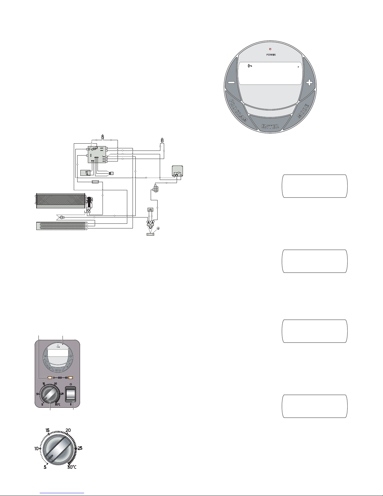
Digital Timer Operation - see Fig. 6
IMPORTANT: DO NOT plug in the appliance where the load
exceeds 16 Amp.
Mode Selection
There are four different operating modes. Press MODE to cycle through
these:
MAN OFF – heat is permanently off
– see Fig. 7. This is also the default
screen.
MAN ON – heat is permanently on –
see Fig. 8.
AUTO DLY – switches the heater
ON and OFF everyday according to
a set daily program – see Fig. 9.
AUTO BLK – switches the heater
ON and OFF according to a set of
programs for weekdays only or
weekends only – see Fig. 10.
Fig. 6
13 : 17
ON
DLY
ADVANCE
AUTO
P1
M
T
W
T
S
S
F
Fig. 7
Fig. 8
Fig. 9
Fig. 10
00 : 00
MANUAL OFF
M
T
W
T
S
S
F
00 : 00
MANUAL ON
M
T
W
T
S
S
F
00 : 00
AUTO
M
T
W
T
S
S
F
DLY
OFF
00 : 00
AUTO
M
T
W
T
S
S
F
BLK
OFF
Page 3

(a)
(b)
(c)
(d)
Set Time
1. Press the ‘Program’ button
ONCE. The clock symbol
appears on the top left hand
side of the screen - see Fig. 11.
The user can now set the clock.
2. The hour digit will flash. T o adjust
the hour use the ‘-’ & ‘+’ buttons. Confirm the hour by pressing
ENTER.
3. Once ENTER has been pressed the minutes will flash. To adjust the
minutes use the ‘-’ & ‘+’ buttons. Confirm the minute digit by pressing
ENTER.
4. Once ENTER has been pressed the arrow will flash next to Mon.
Use the ‘-’ & ‘+’ buttons to set current day and press ENTER to
confirm and return to the default display.
Set Programme
A total of 12 ON/OFF time programmes can be set for operation. There
are two programme options:
OPTION 1; Daily (‘DLY’ on display):
This is a daily program function,
Monday to Sunday with four ON/
OFF program options available - see
Fig. 12.
OPTION 2; Block (‘BLK’ on display):
This is a block program function,
Monday to Friday with four ON/OFF
program options - see Fig. 13 or
Saturday to Sunday with four ON/
OFF program options - see Fig. 14.
Press the ‘PROGRAM’ key twice to
set the programs starting with ‘Daily
ON’ P1.
Setting P1 On Time
1. To set the hour use the ‘-’ & ‘+’
buttons. Confirm the hour digit
by pressing ENTER.
2. T o set the minutes use the ‘-’ & ‘+’ buttons. Confirm the minute digit by
pressing ENTER.
Note: The minutes can only be set in 10 minute blocks.
Setting P1 Off Time
3. To set the hour use the ‘-’ & ‘+’ buttons. Confirm the hour digit by
pressing ENTER.
4. T o set the minutes use the ‘-’ & ‘+’ buttons. Confirm the minute digit by
pressing ENTER.
Repeat steps 1 to 4 to programme P2, P3 and P4. After programming P4
you automatically enter the BLOCK programme option. Repeat steps 1
to 4 to programme P2, P3 and P4. After programming P4 you automatically
exit the BLOCK programme option.
At any time while programming the timer you can press the PROGRAM
button to exit to the default display.
NOTE: Y ou can cycle quickly from daily mode to block modes by pressing
the MODE button.
The Advance Function
When in AUTO MODE, if the ‘+’ button
is pressed for longer than 2 seconds
the programme will ADV ANCE to the
next setting programmed and will
only revert back to the program
when the subsequent programme
time is reached. When the
ADVANCE function is running the ADVANCE segment will be displayed
on the LCD screen - see Fig. 15. If the ‘-‘ button is pressed for longer
than 2 seconds when the ADVANCE programme is running the
ADVANCE feature will automatically be cancelled and the programme
will run as normal.
e.g. If the present time is 14:00 and P1 ON is at 17:00 and P1 OFF is
19:00, if ‘+’ is held for 2 seconds and remains on until 19:00. ADVANCE
disappears from the screen at 17:00 as set program is then running.
Fig. 17
Fig. 11
Fig. 12
Fig. 13
Fig. 14
Key Lock
T o lock the keypad press ENTER and
MODE simultaneously. The key
symbol will appear on the screen
when the keypad is locked – see
Fig. 16. T o unlock the keypad repeat
the action above.
Note- Timer Memory Back Up Batteries – Once the heater has
been left plugged in with the socket switched on for at least 72 hours
the timer’s memory back up batteries will be fully charged.
Once the timer batteries are fully charged, if there is a power cut out or
if the heater is disconnected form the mains from less than six months,
then the timer will continue to keep time, and the settings in the memory
will remain intact.
If however the timer batteries have not been charged fully, or if the
heater is deprived of power for longer than six months, then the time
and programme settings are likely to be lost and you may therefore need
to reset the time and programme before using the ‘AUTO’ MODE again.
General Cleaning
WARNING : BEFORE UNDERTAKING ANY MAINTENANCE OR
CLEANING WORK ON THE APPLIANCE, IMMEDIA TEL Y DISCONNECT
THE ELECTRICITY SUPPLY EITHER BY SWITCHING OFF AT THE
ADJACENT DOUBLE POLE SWITCH OR BY REMOVING THE PLUG
FROM THE SOCKET .
The outside of the appliance should be wiped over with a soft damp
cloth and then dried. Do not use detergents or abrasives.
The filter should be cleaned by gently passing the soft brush attachment
of a vacuum cleaner over the front grille (see ‘d’ in Fig. 17).
Service and Repair
THE INTERNAL CLEANING AND MAINTENANCE WORK SHOULD ONL Y
BE UNDERTAKEN BY COMPETENT PERSONS WITH EXPERIENCE OF
REPAIRING DOMESTIC ELECTRICAL APPLIANCES AND IN FULL
KNOWLEDGE OF THE POSSIBLE HAZARDS INVOLVED.
To ensure the appliance operates efficiently, the following maintenance
should be undertaken periodically. The cover should be removed and
refitted as detailed under ‘Procedure’.
Fan Blades : These should be cleaned by using the soft brush
attachment of a vacuum cleaner. Care should be taken not to damage
the blades.
Filter (see ‘c’ in Fig. 17) : The filter can be removed completely for
cleaning, but generally, provided this is cleaned frequently as detailed
above, this should not be necessary. Where removal of filter is required
for cleaning, the filter retaining wires (see ‘a’ in Fig. 17) can be removed,
allowing the mesh (see ‘b’ in Fig. 17) and the filter to be taken out.
General : With the cover removed, opportunity should be taken to
remove any accumulations of dust from within the unit.
Bearings : Fan and motor bearings should be given one or two (not
more) drops of low viscosity oil (e.g. sewing machine oil) approximately
every 12 months.
Fig. 15
Fig. 16
00 : 00
M
T
W
T
S
S
F
AUTO
ON
DLY
ADVANCE
00 : 00
M
T
W
T
S
S
F
00 : 00
AUTO
M
T
W
T
S
S
F
DLY
OFF
00 : 00
M
T
W
T
S
S
F
BLK
ON
P1
00 : 00
M
T
W
T
S
S
F
BLK
ON
P1
00 : 00
M
T
W
T
S
S
F
Page 4

Thermal Safety cut-out
In the event that the appliance overheats, the cut-out switches the
heater off automatically . To bring the heater back into operation, remove
the cause of overheating, then turn Off the electrical supply to the
heater for a few minutes. When the heater has cooled sufficiently
reconnect and switch On the heater. If the cut-out operates repeatedly,
contact your supplier.
Recycling
For electrical products sold within the European Community.
At the end of the electrical products useful life it should
not be disposed of with household waste.
Please recycle where facilities exist.
Check with your Local Authority or retailer for recycling
advice in your country.
After Sales Service
Your product is guaranteed for one year from the date of
purchase.
Within this period, we undertake to repair or exchange this
product free of charge provided it has been installed and
operated in accordance with these instructions.
Your rights under this guarantee are additional to your statutory rights,
which in turn are not affected by this guarantee.
Should you require after sales information or assistance with this product
please go to www.dimplex.co.uk where you will find our self help
guide by clicking on “After Sales” or ring our helpdesk on 0845 600 5111
(UK) or 01 842 4833 (R.O.I.) .
Spare parts are also available on the website
www.dimplex.co.uk
Please retain your receipt as proof of purchase.
The product complies with the European Safety Standards EN60335-2-30 and the European Standard Electromagnetic Compatibility (EMC)
EN55014, EN60555-2 and EN60555-3. These cover the essential requirements of EEC Directives 2006/95/EC and 2004/108/EC
DIMPLEX
MILLBROOK HOUSE
GRANGE DRIVE
HEDGE END
SOUTHAMPTON
SO30 2DF
[c] GDC Group Ltd,
All rights reserved. Material contained in this publication may not be reproduced in whole or in part, without prior permission in writing of Dimplex.
A division of GDC Group Ltd,
TEL: 0845 600 5111
FAX: 01489 773050
WEBSITE: www.dimplex.co.uk
Republic of Ireland Tel. 01 8424833
 Loading...