

Page 1
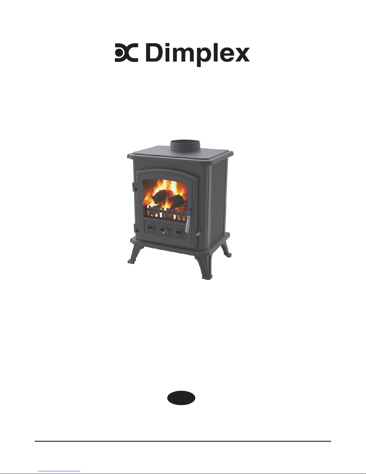
The product complies with the European Safety Standards EN13240 for Room heaters red by solid fuel.
08/51351/0 - Issue 0
UK
Westcott 5 Clean Burn Stove
Please hand these instructions to the stove user when installation
is complete. Leave the system ready for operation and instruct the
user in the correct use of the appliance and operation of controls.
Installation should only be carried out by a suitably qualied
installer that is registered with HETAS (UK) or with the Irish
Nationwide Fireplace Organisation (INFO).
Installation must comply with Building Regulations.
Page 2
1
2
3
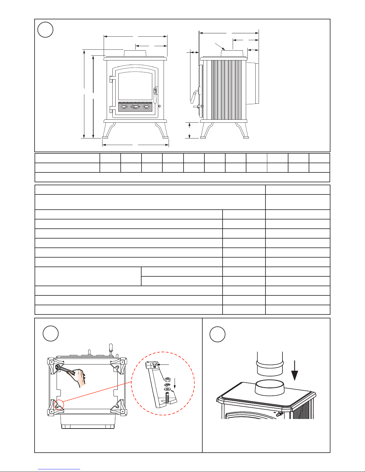
Table 1 - Dimensions A B C D E F G H J K L
Westcott 5 Clean Burn 580 540 416 208 434 105 55 393 175 75 128
Note: All Dimensions in mm. Dimensions stated may be subject to a slight ± variation. ( 25.4mm = 1”)
Table 2 - Technical Specication Westcott 5 Clean Burn
Fuel Type
Wood Only
(Moisture <20%)
Nominal heat output kW 4.9
Efciency % 72
CO Emission (@13% O2) % 0.36
Flue Gas Temp °C 313
Flue Gas Mass Flow g/s 5.1
Refuel Period hr 1
Safe Distance to Combustibles
Sides mm 450
Rear mm 400
Flue Outlet Size mm 125
Product Weight kg 75
Additional Room Ventilation Required cm² See Table 4
A
B
C
D
E
F
G
K
J
H
L (Dia)
x 4
A
Page 3
H
MIN
150mm
X
X
T
T
MIN
150mm
MIN
125mm
See Table 3
Solid, non-combustible
material e.g. masonary
or concrete
4
5
6 7
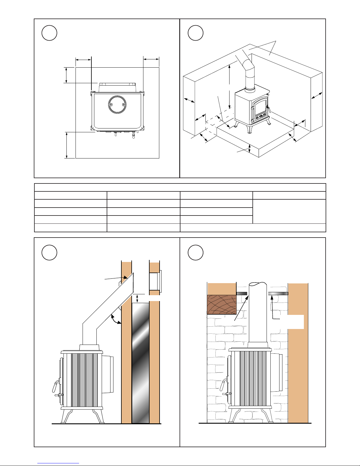
Table 3 - Position of Hearth & Appliance from adjacent walls
Hearth distance ‘X’ from wall Appliance distance from walls Min Wall Thickness ‘T’ Min Wall height ‘H’
0mm 0 - 50mm 200mm Height of appliance +300mm
or 1200mm from hearth
(whichever is greater)
0mm 51 - 150mm 75mm
0 - 150mm 150 - 300mm 75mm
+150mm +300mm No Minimum Requirement
45°
Max
Seal with fire
proof lagging
150 Max
CLOSURE
PLATE
SEAL
Z
Z
Z
300
CONSTRUCTIONAL HEARTH
NON COMBUSTIBLE
125mm THICK MINIMUM
Z = At least 150mm or to a
suitably heat resistant wall
(See table 3)
Page 4
10
A
B
C
8 9
Page 5
IMPORTANT: THESE INSTRUCTIONS SHOULD BE READ CAREFULLY AND RETAINED FOR FUTURE REFERENCE
Important Safety Advice
Please read these instructions carefully before installing
or using this appliance. Failure to do so may result in
damage to persons and property.
Installation of this appliance must be carried out by a
suitably qualied competent person in accordance with
all Building Regulations, including those referring to Local
Authority Bye-Laws, National and European Standards
and Codes of Practice.
Do not install this appliance on a shared ue.
This appliance operates at very high temperatures and
retains its heat for a period after use. Do not touch any
surfaces while in use. All persons including children and
the inrm should be warned of this and not allowed to
touch any surfaces while in use. Please use a suitable
reguard to prevent contact when in use.
Do not place any photographs, paintings, TV’s or other
combustible items near the appliance as exposure to
hot surfaces will cause damage. Maintain safe distances
from combustibles in all cases in accordance with these
instructions – please refer to installation.
The operator must use the tools provided. The mitten
provided is a tool.
Do not t an extractor fan in the same room as this
appliance.
Ensure that there is adequate ventilation in the room in
accordance with building standards. Do not obstruct any
of the air inlets or outlets on the appliance.
A ue damper should not be tted when burning solid
fuels other than wood.
This appliance is for domestic heating use only in
accordance with these operating instructions. Do not
make any unauthorised changes to the appliance.
Only use recommended fuels. Do not burn petroleum coke
fuels, household waste or plastic in this appliance.
Burn only wood with a low moisture content - burning soft
or wet wood will only result in a build up of tar in the stove
and the chimney and will cause staining of the glass.
Do not use ammable liquids to ignite the re.
Avoid the use of aerosols in the vicinity of the stove when
it is in operation.
Clean your chimney at least once a year and clean the
ue way weekly to ensure there are no blockages. Do not
allow a build up of ash to occur in the ash pan as this will
cause the grate to burn out prematurely.
Re gu lar maintenance sho ul d be carried out by a
Competent Engineer.
Health and Safety Precautions
Handling: Adequate facilities must be available for the unloading
and handling of this appliance. This product is heavy and should
be handled with care. When handling or servicing this stove care
should be taken to avoid the possibility of personal injury. Use
protective clothing.
Fire Cement/Glue: Some types of re cement/glue are caustic
and should not be allowed to come into contact with the skin. Use
suitable protective gloves when handling. In case of contact, wash
immediately with plenty of water.
Asbestos: This appliance contains no asbestos. If there is a
possibility of disturbing asbestos as a result of installation then
specialist guidance must be sought prior to installing.
Installation Instructions
General
These instructions give a guide for the installation of the stove but
in no way absolves the installer from responsibilities to conform
to all relevant standards relating to the installation of solid fuel
appliances.
We recommend that for UK installations a HETAS registered
installer should be used, who will be able to give a Certicate of
Compliance that installation complies with Building Regulations.
In Ireland a registered installer from the Irish Nationwide Fireplace
Organisation should be used. Site conditions will vary, a certain
amount of customisation of installation may be required.
Please note that to the best of our abilities these instructions are
correct at time of printing, however we cannot be held responsible
for any differences in legislation which may occur in the future.
Assembly of the stove
To make the product easier for handling on installation, remove
the bafe plate, side bricks, back brick and door. Place these in
a secure place to avoid damage. These must be retted after
installation.
The legs and other xings are packed in the ashpan for safe
keeping in transport. Fix the legs to the underside of the product
using the bolts provided (Fig 2).
The stove is supplied for top ue connection only. Fire cement or
other suitable high temperature sealant must be used when tting
the ue to the ue collar (Fig 3) to make airtight connection.
Chimney
Before installing, check the chimney is in good condition; dry and
free from cracks and obstructions. The diameter of the chimney
ue should not be less than 175mm and not more than 230mm.
If any of these requirements are not met, the chimney should be
lined by a suitable method by a qualied person.
The chimney height and the position of the chimney terminal should
conform to Building Regulations. If you have any doubts about the
suitability if your chimney, consult your local dealer or stockist. The
chimney and ue pipe must be swept before connection to the
stove and swept at least once yearly thereafter.
If there is no existing chimney then either a prefabricated block
chimney or a twin walled insulated stainless steel ue to BS4543
UK
Westcott 5 Clean Burn Stove (WST5SE)
- 1 -
Page 6
can be used. These chimneys must be tted in accordance with
the manufacturers instructions and in compliance with Building
Regulations.
This product must not be installed on a shared ue.
Flue Deposits
If the chimney was previously used as an open re, it is possible
that the higher ue gas temperatures generated by the stove
may loosen deposits that were previously adhered to the inner
surface of the ue pipe which could cause blockage of the ue
pipe. We recommend that in this situation a second sweeping of
the chimney should be carried out within one month of initial stove
use after installation.
Room Ventilation
For safe operation this stove must be provided with combustion
air supply in addition to normal room ventilation, in accordance
with Building Regulations. Minimum ventilation requirements vary
depending on whether the dwelling is considered to be of standard
construction or of airtight construction, or if a ue draught stabiliser
has been tted. The required open air vent sizes are as follows:
Table 4
Standard build dwellings {air permeability >5.0m³ /(h.m²)}
No Flue Stabiliser No additional vent required
With Flue Stabiliser 15 cm²
Airtight build dwellings {air permeability ≤5.0m³ /(h.m²)}
No Flue Stabiliser 27 cm²
With Flue Stabiliser 42 cm²
Flue Draught
The chimney should be checked before the stove is installed to
ensure that there is adequate ue pull. The draught can be checked
initially by using a smoke match close to the ue opening. If the
chimney doesn’t pull the smoke it may suggest that the chimney
needs further attention. Any remedial work to the chimney ue
should be carried out by a suitably Qualied Engineer.
A ue draught of minimum 12 Pascal to maximum 25 Pascal is
required for satisfactory appliance performance. The ue draught
should be checked under re at high output and if it exceeds the
recommended maximum a ue draught stabiliser (or ue damper
as it is also known) must be tted so the rate of burning can be
controlled and prevent overring.
An extractor fan must not be used in the same room as this
appliance.
Floor Protection & Installation Clearances
In all instances the stove should be positioned on a noncombustible hearth. The construction of the hearth must conform
to Building Regulations, must be rm, non-combustible and capable
of supporting the stove. Care should be taken to ensure the stove
is level and the hearth is secure. The hearth itself should not be
less than 125mm thick, including the thickness of the oor and
any decorative top surface (e.g. tiling). Allow an apron of at least
300mm at the front of the stove in case of spills when de-ashing.
(Fig 4) shows the minimum distances required from the hearth
edge to the sides of the stove.
The stove can also be recessed in a suitable sized replace. We
recommend a permanent free air gap of at least 100mm should be
left around the sides and rear where possible and 300mm around
UK
- 2 -
the top to obtain maximum heat output and for access to the rear
of the stove for maintenance and cleaning.
Place the product in the desired location on reproof hearth taking
note of installation clearances from adjacent walls (Fig 5). Adjust
the screws on the bottom of the feet to ensure the stove is level
and steady (see ‘A’ Fig 2). The stove can be screw xed to the
oor when placed in the desired position, using the holes provided
in the feet.
The minimum safe distances to combustable materials that
must be observed are 450mm (sides) and 400mm (rear).
Any surrounding combustible material should not exceed 80°C.
Furniture and general soft furnishings should be kept at a safe
distance of 900mm from the stove and ue pipe.
Flue Pipes
The ue pipe used to connect to the stove should be made of cast
iron, 316 grade stainless steel or vitreous enamelled steel, nominal
thickness 1.2mm. The diameter of the ue pipe should be 125mm
(5”) for the Westcott 5 clean burn model.
Connect the ue pipe to the stove making sure that it ts snugly
into the base of the ue collar (Fig 3). Seal the collar and ue
connection with re cement or with other suitable high temperature
sealant. Add ue sections as required; note that all ue sockets
must face upwards. Ensure that the ue pipe end is no closer
than 76mm to the side or rear of the chimney walls. It is essential
that all connections between the stove and the chimney ue are
sealed and made airtight.
Avoid using bends greater than 45° to the vertical (Fig 6). All ue
pipes should be as close to vertical where possible. Both chimney
and ue pipe must be accessible for cleaning and if ALL parts
of the chimney cannot be reached, a soot door must be tted to
enable this to be done.
Typical installation for Inglenook Fireplaces
Inglenook replaces can have very large bore chimneys (Fig 7).
Check with your installer – you may need a stainless steel exible
ue liner for solid fuel tting.
Flue Damper (Not Supplied)
When burning wood, a ue damper may be tted to reduce the
draught through the stove if the draught is too high. When the
damper is set in the open position the chimney draws at full
draught, increasing the volume of air ow through the stove and
ue. Shutting the damper restricts the ow, slowing the rate of
burning.
The damper should be tted to the stove ue and should be the
same size as the ue pipe. As a rule it should be tted no closer
than 700mm from the ue outlet of the appliance.
A ue damper should not be tted when burning solid fuels
other than wood.
Commissioning
Upon completion of installation, the stove and ue system should
be tested by a suitably qualied person to make sure it is safe for
normal use. A smoke draw test should be completed to check for
soundness of joints and seals and also that all smoke and fumes
are taken from the appliance up the chimney and emitted safely.
First warm the ue with a blowlamp or similar for about 10 minutes.
Place a lit smoke pellet on the centre of the grate with the air
controls open. Close the door – the smoke should be drawn up the
ue and be seen to exit from the ue terminal. Complete the test
with all windows and doors shut in the room where the appliance
Page 7

is tted. If a ceiling fan is present it must be operated on max for
the duration of the test. If there are any extraction fans in adjacent
rooms these too must be operated on maximum setting during the
test with the interconnecting doors open. If any spillage occurs,
recheck the suitability of the ue system making sure there is
adequate air supply to the room (as per Building Regulations).
Light the appliance and slowly increase the temperature to medium
operating levels. The stove should not be run at full output for the
rst 3-4 burn cycles. Open the main re door when the appliance
reaches normal operating condition and carry out a spillage test
using a smoke match or pellet around the door opening. If any
spillage occurs, open all windows, allow the re to go out and
recheck the ue system and ventilation.
Operating Instructions
Please read fully these operating instructions and advise any other
users of the correct operating procedures for this stove.
Warning: The door and operating handles become hot when
the stove is in use. For your safety use the glove provided.
This stove will remain hot for a considerable time after the
re has extinguished. This stove should not be operated with
the door left open.
General
Unlike conventional stoves, this stove uses the down burn principle
where the ame path rises up to the bafe plate in the top of the
stove, circulates around the bafe mixing with secondary air from
the airwash above the door, then back down and out through the
re box outlet. The re box outlet is the narrow throat in the back
brick located at the bottom rear of the re box. Behind the back
brick is a combustion chamber that has its own (tertiary) air supply.
As smoke enters the combustion chamber it is injected with preheated air which further increases the temperature as it burns
off smoke particles, creating cleaner emissions. The hot gasses
then circulate around the inner bafe and out the main ue outlet
entering into the connecting ue pipe.
Air Controls
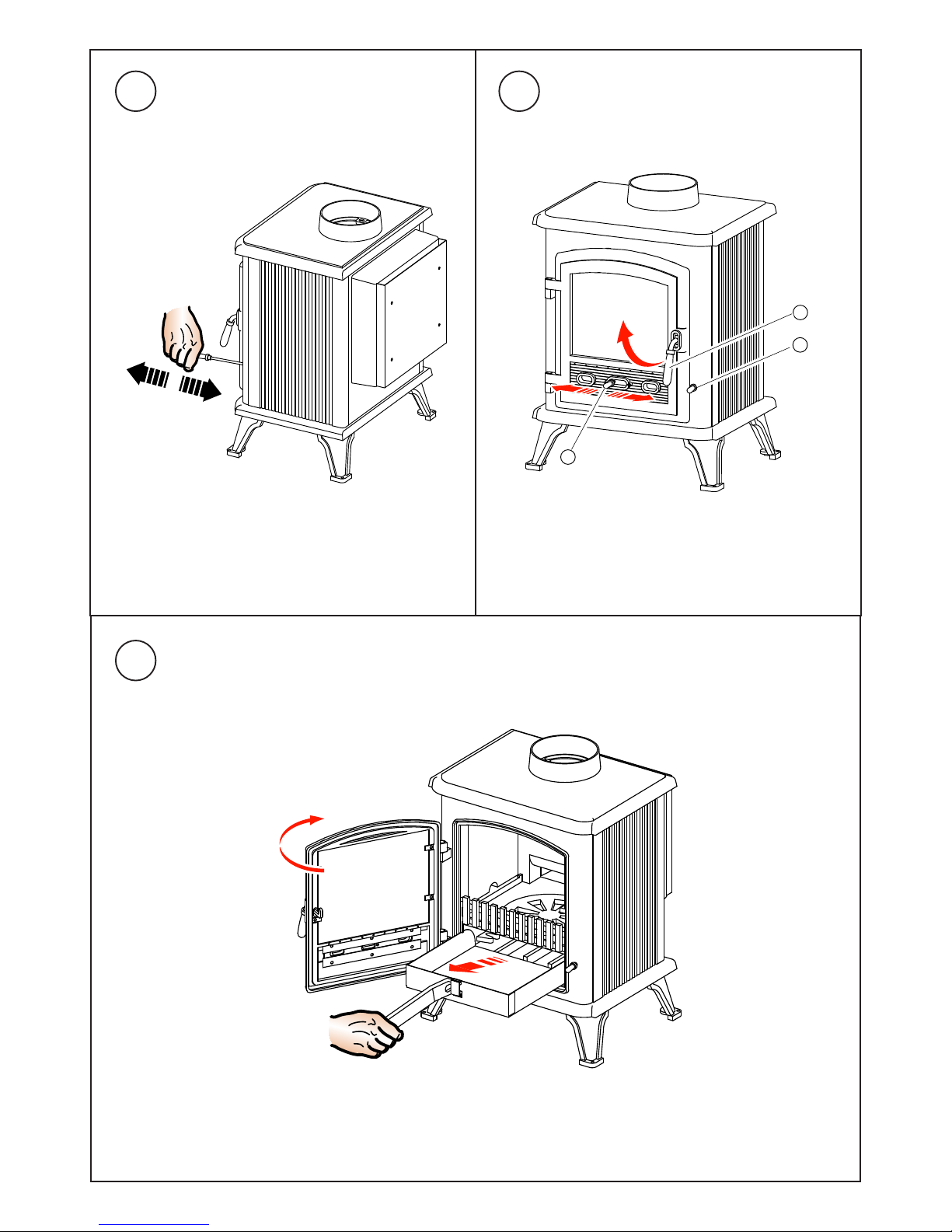
Primary air is controlled via the sliding vent (A - Fig 9) in the bottom
of the door; this provides a conventional air draught to the bed of
the re. (+) indicates more air, (-) indicates less air, (+) and (-) are
marked on the primary air controls.
The secondary and tertiary air supplies create the clean burn
function; these air supplies are not adjustable. The primary air
supply controls the burn rate. There is a xed primary air bleed
on the door located above the primary air slide.
Initial Firing of Stove
We recommend that you have 3-4 small res before you operate
your stove to maximum heat output. This is to allow the paint to cure
and the castings to relax and consolidate location. We recommend
this ‘running in’ procedure after long idle periods to preserve the
life of the stove. During this you may notice an unpleasant smell.
It is not toxic but for your own sake we would suggest that during
this period you leave all doors and windows open.
Lighting the Stove
Place re lighters or paper and kindling on the grate. Light the
re at base leaving all air controls open. Allow the fuel to reach
a steady glow and build the re up gradually. Once you have a
good re established across the grate bed, further fuel can be
added as required.
UK
- 3 -
Running the Stove
When your fuel is well alight you can start to restrict the primary
air intake. Your stove is burning with maximum efciency when a
bright re is achieved using minimum air inlet. The stove is not
suitable for overnight burning.
Notes on Wood Burning
Wood burns best on a bed of ash and it is therefore only necessary
to remove surplus ash from the grate occasionally. Burn only
dry, well seasoned wood (< 20% moisture), which should have
been cut, split and stacked for 12 months with free air movement
around all sides of the stack to enable it to dry out. Burning wet or
unseasoned wood will create tar deposits in the stove and chimney
and will not produce a satisfactory heat output. When loading wood,
make sure that the end grain of the wood in the stove is pointing
away from the glass otherwise the moisture and gases coming
from the end grain of the wood will dirty the glass.
The maximum log length that should be used is 300mm (12”).
This stove is suitable for burning wood only. Do not use this stove
as an incinerator for household waste as fumes from plastic, etc
will cause pollution to the atmosphere and will cause damage to
the stove.
Petroleum coke fuels, household waste or liquid fuels must
not be burned in this appliance.
Shutting Down
To shut down the stove, close the primary air controls and then
the secondary air controls by moving both sliders to the left. If the
controls are left in this position the re will be starved of air and
will go out. To revive the re open the primary air controls rst,
then the secondary air.
De-Ashing
To de-ash the grate draw the grate rod (C - Fig 9) forwards and
backwards with a slow positive action repeatedly (Fig 8) so the
ash falls though to the ashpan. Use the poker tool to remove any
ash build up under the rebrick at the rear of the grate as this is
where the main ue exit is located.
The ash pan should be emptied each time after operating the stove
so not to let build up of ash occur. Where possible, it is best to
wait until the stove and ash has cooled before removing the ash
pan. To remove, open the stove door by lifting the handle upward
(B - Fig 9) then using the riddle handle lift the ash pan out of the
re (Fig 10). For efcient burning of your appliance, make sure
the grate is clear of burnt debris; e.g. nails, etc.
Shut down Periods
If shutting down the stove for long periods (e.g. for summer months)
make sure that all ash is removed from the stove and that the
chimney ue ways and bafe plate are brushed clean. When the
stove is cold a vacuum cleaner may be used to remove any residual
ash or soot. Close the door and leave all air inlets open fully. This
action will ensure air circulation through the appliance and will help
to avoid corrosion and condensation within the appliance during
this shut down period.
Safety Notes for Your Guidance
FIRES CAN BE DANGEROUS.
Always use a re guard in the presence of children, the elderly
or the inrm. Inform all persons the dangers of high temperatures
during operation of the appliance including the stove pipe.
Use operating tools provided.
Page 8

DO NOT OVER FIRE.
It is possible to re the stove beyond its design capacity. This could
damage the stove, so watch for signs of over ring. If any part of
the stove starts to glow red, the stove is in an over re situation
and the controls should be adjusted accordingly to reduce air
intake. Never leave the stove unattended for long periods without
adjusting the controls to a safe setting. Careful air supply control
should be exercised at all times.
Warning - Fume Emissions
Properly installed and operated, this appliance will not emit fumes.
Occasional fumes may occur if the door is open when de-ashing
and refuelling. Persistent fume emission must not be tolerated. If
fume emission does persist, then the following immediate action
must be taken:
1. Open doors and windows to ventilate the room.
2. Let the re out, or eject and safely dispose of fuel from the
appliance.
3. When the stove has cooled, check for chimney ue blockage
and clean if required.
4. Do not attempt to relight the re until the cause has been
identied. If necessary seek professional advice.
General Maintenance
Bafe Plate: This should be removed at least once a month to
prevent any build up of soot or ash, which could lead to blocked ue
ways and dangerous fume emission. If the bafe plate is removed
the chimney/ueway can be swept through the appliance.
Stove Body: The stove is nished with a heat resistant paint and
this can be cleaned with a soft brush. Do not clean while the stove
is hot, wait until it has cooled down. The nish can be renovated
with a suitable brand of paint.
Glass Panels: Clean the glass panels when cool with a proprietary
glass cleaner. Highly abrasive substances should be avoided as
these can scratch the glass and make subsequent cleaning more
difcult. Wet logs on heated glass, a badly aimed poker or heavy
slamming of the doors could crack the glass panels. The glass will
not fracture from heat.
Chimney: Check your chimney each year before starting to use
your stove for the winter. Birds may have nested in the chimney or
masonry may have cracked. Both chimney and ue pipe must be
swept at least once a year by a Qualied Chimney Sweep.
Troubleshooting
1. Poor heat output
a. Stove too small for room: Seek advice from a Qualied Heating
Engineer as to (kW) output required for the room size. As a
guideline the volume of the room in cubic feet divided by 500;
e.g. room 15’x15’x8’ would require 3.6kW approx.
b. Chimney and/or ue pipe restricted, room ventilation restricted:
On installation these should have been checked but regular
maintenance is necessary as conditions can change; e.g. soot
build up, birds nesting, masonry fall, dust build up or furniture
blocking vents.
c. Poor quality fuel: Only burn dry seasoned timber, soft woods
have a lower heat output than hard woods per hour. Solid
fuels vary in heat value; check with your coal merchant as to
suitability.
2. Dirty Glass Panel
a. Generally caused by poor fuel quality, see (1c)
b. Use secondary air slide (Airwash) for glass panel
c. Fire burning too low, open air vents on stove to create hot re;
this may ‘burn’ glass clean.
d. If glass requires cleaning use glass cleaner recommended by
your supplier; only use glass cleaner on cold glass. DO NOT
USE any abrasives or scrapers as these will scratch glass and
increase future tar build up making it harder to clean.
3. Unburnt Fuel in Firebox
Insufcient air reaching fuel. Open primary air slide, this will supply
combustion air to burn fuel fully (unless it has reached a ‘point of
return’). Check if the ash pan is full and empty if required. De-ash
with the riddler to make sure the grate is not blocked and check
for jammed clinker or nails when the re is out and the stove has
cooled.
4. Smoke and Fumes Entering Room
These are very dangerous and must NOT be tolerated. Open
window and allow re to burn out. Seek expert advice immediately.
DO NOT USE stove until the problem is solved.
5. Chimney Fire
Identied by loud roaring sounds, dense smoke and sparks emitting
from chimney.
1) Raise the alarm to let others in the house know.
2) Call the Fire Brigade.
3) If possible, shut down the air supply by closing air vents and
DO NOT open the stove door.
4) If possible, move back any furniture, rugs or other items that
could catch re.
5) Retire to a safe distance from the house until the re has gone
out and it is safe to return.
Regular chimney maintenance will prevent chimney res. Seek
advice from a Qualied Chimney Sweep. Chimneys must be
checked annually.
After Sales Service
Your Dimplex Stove is guaranteed against defects arising from
faulty manufacture for 1 year subject to the following conditions.
Failure to comply with these conditions will invalidate the
gaurantee:
The receipt must be kept as proof of purchase. •
Your Dimplex stove must be installed by suitably qualied •
individual (HETAS Engineer or equiva lent) and up on
installation a Certicate of Compliance must be presented.
The guarantee is 1 year from date of purchase.•
The guarantee does not cover parts that are deemed to be •
replacable through normal usage of the stove. These include:
glass panels, rope seals, bottom grate or rebars, ashpan,
rebricks, cast iron liners, riddling lever, bafe plate, log
guard.
Only genuine Dimplex spare parts should be used. Parts that •
may need occasional replacement are: rebricks, ashpan, re
grate, log guard.
Should you require after sales service or should you need to
purchase any spares, please contact the retailer from whom the
appliance was purchased. Please do not return a faulty product
to us in the rst instance as this may result in loss or damage and
delay in providing you with a satisfactory service. Please retain
your receipt as proof of purchase.
UK
- 4 -
Page 9
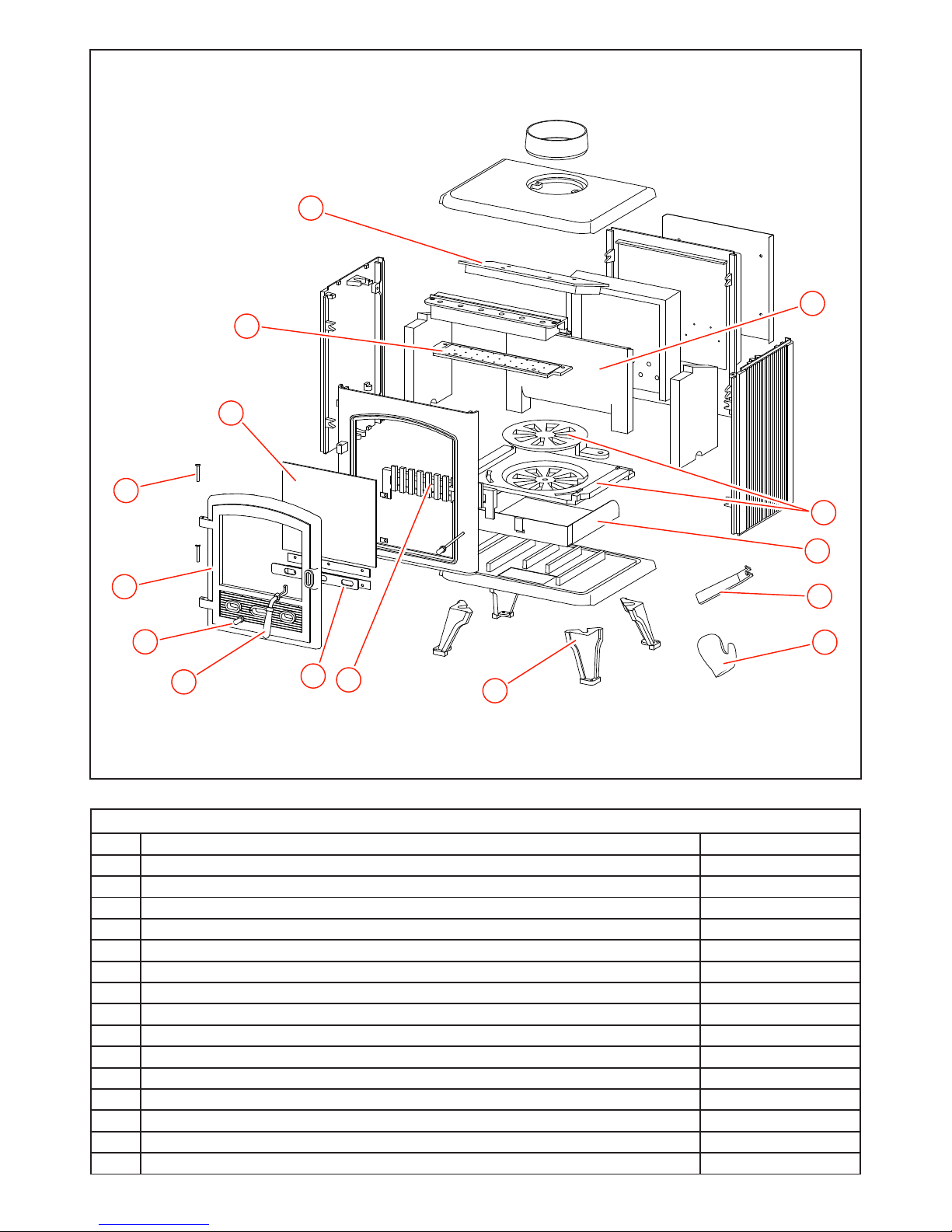
10
9
12
1
14
7
8
11
5
13
3
4
15
6
2
WESTCOTT 5 CLEAN BURN
WESTCOTT 5 CLEAN BURN STOVE - SPARE PARTS
Item Description Part No
1 Door MF09015
2 Grate Accessory Pack (incl Grate Outer, Grate inner, Con Rod) MF10005
3 Front Bar (log bar) MF09018
4 Air Wash Plate MF10006
5 Top Brick Bafe Plate Assembly MF10007
6 Grate/Ashpan Operating Tool MF09007
7 Legs Accessory Pack (x2 off) MF09009
8 Primary Air Slide MF09021
9 Air slide knob Accessory Pack (x1 steel, x1 black nish) MF09011
10 Door Handle Accessory Pack (x1 steel, x1 black nish) MF09010
11 Ash Pan MF09022
12 Hinge Pins (x2 off) MF09035
13 Heat Bricks Accessory Pack (x2 side bricks, x1 rear brick) MF10008
14 Door Glass Accessory Pack (includes clips) MF09024
15 Mitten MF09036
Page 10

Page 11

Page 12

DIMPLEX
MILLBROOK HOUSE
GRANGE DRIVE
HEDGE END
SOUTHAMPTON
SO30 2DF
TEL: 0845 600 5111
FAX: 01489 773050
WEBSITE: www.dimplex.co.uk
Republic of Ireland Tel: 01 842 4833
[c]A Division of GDC Group Ltd.
All rights reserved. Material contained in this publication may not be reproduced in whole or in part, without prior permission in writing of
GDC Group Ltd.
 Loading...