

Dimplex RSH Series, RDH Series, TWH Series, RSH Installation And Operating Instructions Manual
Page 1
Installation and
Operating Instructions
Fan Forced Wall Heater
RSH/RDH/TWH Series
Installation Instructions
Congratulations on purchasing a small wall heater from
Dimplex North America. Your heater is manufactured using
the highest quality materials and workmanship and will
provide many years of trouble free service.
This heater is designed for permanent installation only,
care should be taken to install according to the following
instructions. All required clearances should be maintained, in
addition all electrical wiring and connections should comply
with local electrical codes.
!
NOTE: It is extremely important to read all information
labels. Care must be taken to ensure that the heater is
rated the same voltage as the electrical supply wires.
Failure to do so could result in unsafe heater operation as
well as damage to the unit. If replacing an existing heater,
check the labels of the old heater to ensure the voltage of
the new heater is compatible.
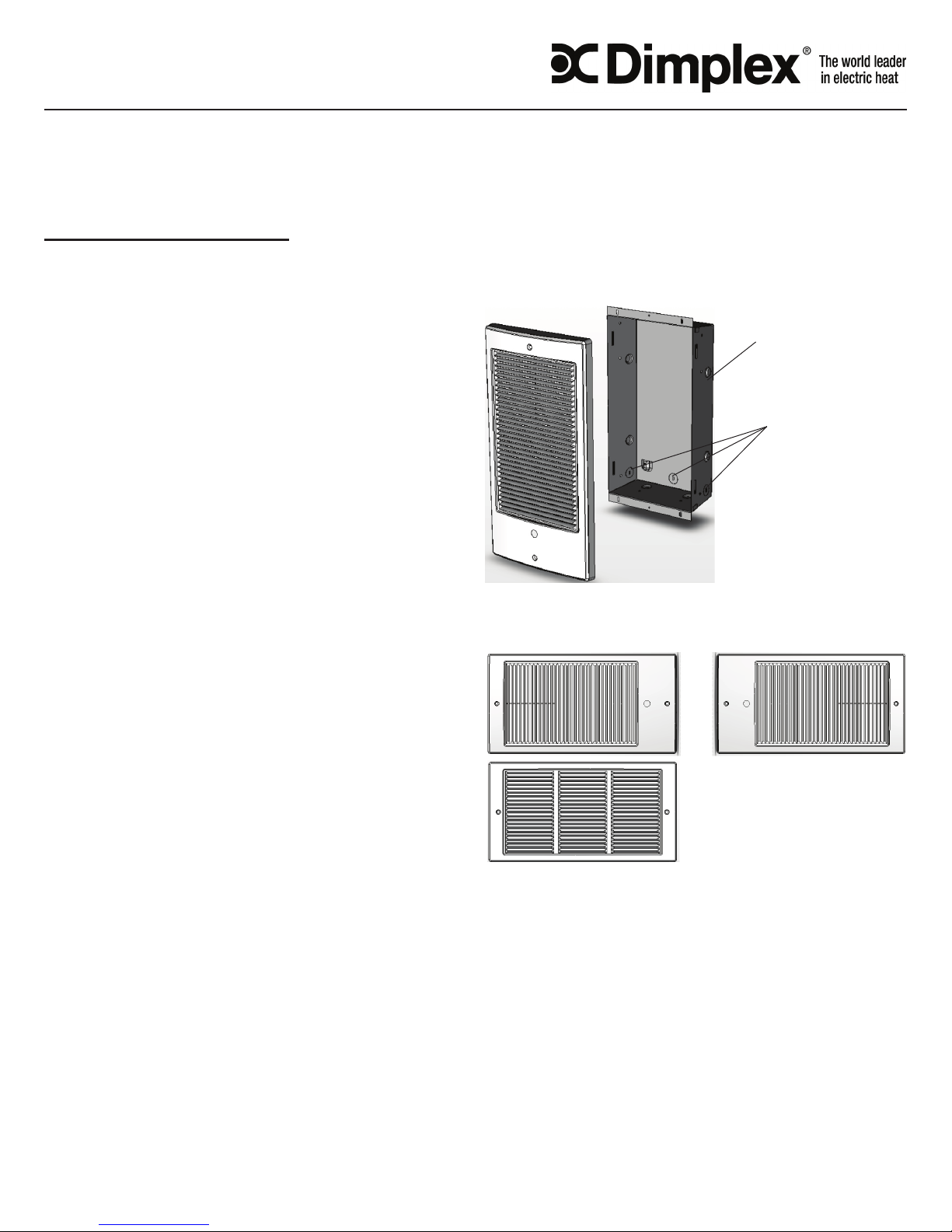
Figure 1
6902270000
Multi-Directional Grill Orientation
for use with 6902270000 RSH/RDH/TWH Series
Heaters
Recess Box
Wiring Access
All units should be controlled by means of a regulating
thermostat. Certain models only are provided with built in
thermostats, check the Model Key Information section for
verication. Wall thermostats should comply with the voltage
and wattage of all heaters on the circuit. Built in thermostats
are not suitable for Register Grill Models.
All installations require the following components:
1) Recess Mount Box (Model 1011650100)
2) Heater Assembly (See nameplate Label)
3) Grill (Either Multi- Directional Style or Register Style)
An optional Surface mount box is available for installations
that are not recessed in wall cavity.
Step 1 – Placement
All units are designed for placement in either interior or
exterior walls. Care should be taken to provide a minimum
of 8" clearance from oors, ceilings and adjacent walls.
Once installed, the airow through the heater should not
be blocked in any way. Maintain three (3) feet clearance of
objects from the front of unit. Maintain a spacing of three
(3) feet between heaters in order to prevent re-circulation
of heated air. Insulation surrounding the back and sides of
the recess mount box will not affect performance. Ensure
insulation is rated for temperatures up to 85oC.
!
NOTE: Certain ooring and wall covering materials
(particularly those incorporating clear vinyl materials tend
to distort at temperatures in the vicinity of 60 C ( 140 F ).
Material shall be checked prior to installation to determine
7207160100rev02
Figure 2
!
NOTE: Maintain a minimum clearance of 8” from adjacent
if discoloration will occur. Units are not approved for
placement in oors or ceilings. Do not install in any area
where combustible vapors, gases, dusts or liquids are
present. Fire or explosion may occur.
Alternate Multi-Directional Grill Orientation
Register Grill
Orientation
walls, oors and ceilings on all four sides of the grill
Step 2 – Mounting The Recess Box
Determine the desired orientation of unit. Provide an
opening in wall 14 ¼” x 8 5/8" x 3 3/8" deep minimum.
Care should be taken to install the recess box in the correct
orientation to accommodate grill. Note the position of
the electrical entry knockouts and orient recess box
according to Figure 1. Ensure all required clearances are
met.
Page 2
Ensure recess box anges are ush with the nished
PRODUCT LEGEND: X YY R WW VV B T C Z
X
YY
R
WW
VV B T C Z
R
RETAIL
SH
SINGLE ELEMENT
R
REGISTER GRILL
05
500
07
240
B
BULK PACKAGING
T
THERMOSTAT
C
WALL CAN
W
WHITE
T
COMMERCIAL TRADE
DH
DOUBLE ELEMENT
07
750
10
240
A
ALMOND
WH
SINGLE ELEMENT
10
1000
11
120
15
1500
21
208
20
2000
31
240/208
wall surface. For new construction, the sides of the recess
box are marked with guidelines to allow for ½” and 5/8“
drywall thickness if drywall is to be added at a later date.
Secure recess box to studs with screws using holes provided
on sides or ange of recess box. Remove appropriate
electrical knockout and secure supply wire using an
approved strain relief connector leaving 6" of wire leads in
the recess box.
Step 3 - Mounting the Heater Assembly
Insert the heater assembly into the recess box ensuring that
the tab on the heater assembly slides into the slot in the
recess box. Ensure the heater assembly is fully seated and
secure to the recess box using the captive screw provided.
Step 4 –Electrical Connections
WARNING: Hazard of severe shock.
CAUTION: Disconnect all power coming to heater at
main service panel before wiring or servicing.
Turn off power supply at the electrical panel. Route supply
wires from circuit breaker through wall thermostat to heater.
For models with built in thermostat route from circuit breaker
to heater.
Supply wire must be of two wire plus ground variety, with
a rating capable of handling all loads on the circuit. Supply
wire should be rated for a minimum of 60C. Make electrical
connection according to relevant wiring diagrams. Make
connections using approved wire nut connectors and secure
the grounding wire to the ground screw on the heater
chassis. On models with Register Style Front Grills only, a
terminal box cover plate is provided. Insert the tabs of the
cover plate into the slots and secure the other side of plate
with the screws provided.
Step 5 – Secure the Front Panel
If your unit has a built in thermostat remove the plug on the
front panel. Fasten the Front Grill using the screws provided.
It is important to note that the front grill is oriented in the
required positions shown in Figure # 1 and on the Multi –
Directional grill. For units with built in thermostat push knob
onto thermostat shaft through plug hole.
Operation And Maintenance
CAUTION: Disconnect all power coming to heater at
main service panel before wiring or servicing.
For units with built in thermostats, rotate the thermostat
knob fully clockwise. Heater should activate. When the
room reaches the desired temperature, slowly rotate the
knob counterclockwise until unit shuts off. The heater will
automatically cycle around this preset temperature setting.
All units contain an Automatic Reset High Temperature
Cutout, which will shut the heater off in the event of
abnormally high operating temperatures. In addition a Red
Warning Light will activate providing a visual warning. If this
condition exists, disconnect all power to the unit and call a
licensed electrician for service. Do not use heater until the
problem is determined and corrected. ENSURE POWER TO
THE UNIT IS DISCONNECTED PRIOR TO SERVICING OR
PERFORMING CLEANING
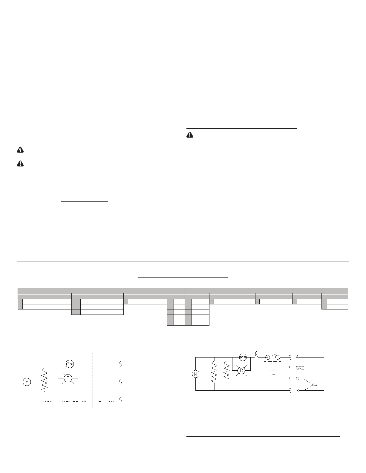
RSH & TWH Models Wiring Diagram
Basic Heater Field Connection
High Limit
Motor
Element
(120V Marked N)
!
NOTE: All units rated for 240/208 V provide 76% wattage of
Black
White
240V rating when connected to 208 V.
7207160100rev02
Model Key Information
L1
Ground
White Neutral 120V
Black L2 for 240V
Motor
!
NOTE: For reduced heat output do not connect wire C to 240 V
line (L2). Wire C must be capped off using a wire nut supplied by
the customer when not used.
Cat. No. Volts Wattage Connections
RDH2010 or RDHR2010 240 2000W L1-A, L2-B & C
1000W L1-A, L2-B ONLY*
RDH1507 or RDHR1507 240 1500W L1-A, L2-B & C
750W L1-A, L2-B ONLY*
RDH Models (Double element) Wiring Diagram
High Limit
Thermostat
Black
Blue
Element
Red
Optional *
240 Volt
Line (L1)
240 Volt
Line (L2)
Page 3

Register Grill
Heater Assembly
Multi-Directional Grill
Recess Box
Optional
Surface Box
Terminal Box Cover
(Required for
Register Grill only)
Replacement Parts Part # Replacement Parts Part #
Grills Single Element
Multi - Directional Grill - Almond TWHA 120V 500W 2200520100
Multi - Directional Grill - White TWHW 120V 750W 2200520200
Register Grill - Almond TWHRA 120V 1000W 2200520300
Register Grill - White TWHRW 120V 1500W 2200520400
Motors 240/208V 500/375W 2200520700
120 V models 2000060003 240/208V 750/500W 2200520800
240/ 208 V models 2000060001 240/208V 1000/750W 2200520900
Fan Blade 5300130100 240/208V 1500/1125W 2200521000
High Limit Cutout 00009201 240/208V 2000/1500W 2200521100
Recess Mount Box TWHC
Double Element
240/208V 2000/1500W 2200540900
240/208V 1500/1125W 2200540800
Accessories
TWHT1 _ Single Pole Thermostat Kit TWHSBA Surface Mount Box - Almond
TWHT2 _ Double Pole Thermostat Kit TWHSBW Surface Mount Box - White
Dimplex North America Limited
1367 Industrial Road Cambridge ON Canada N1R 7G8
1-888-346-7539 www.dimplex.com
In keeping with our policy of continuous product improvement, we reserve the
right to make changes without notice.
7207160100rev02
 Loading...