

Page 1
Owner’s Manual
Model's
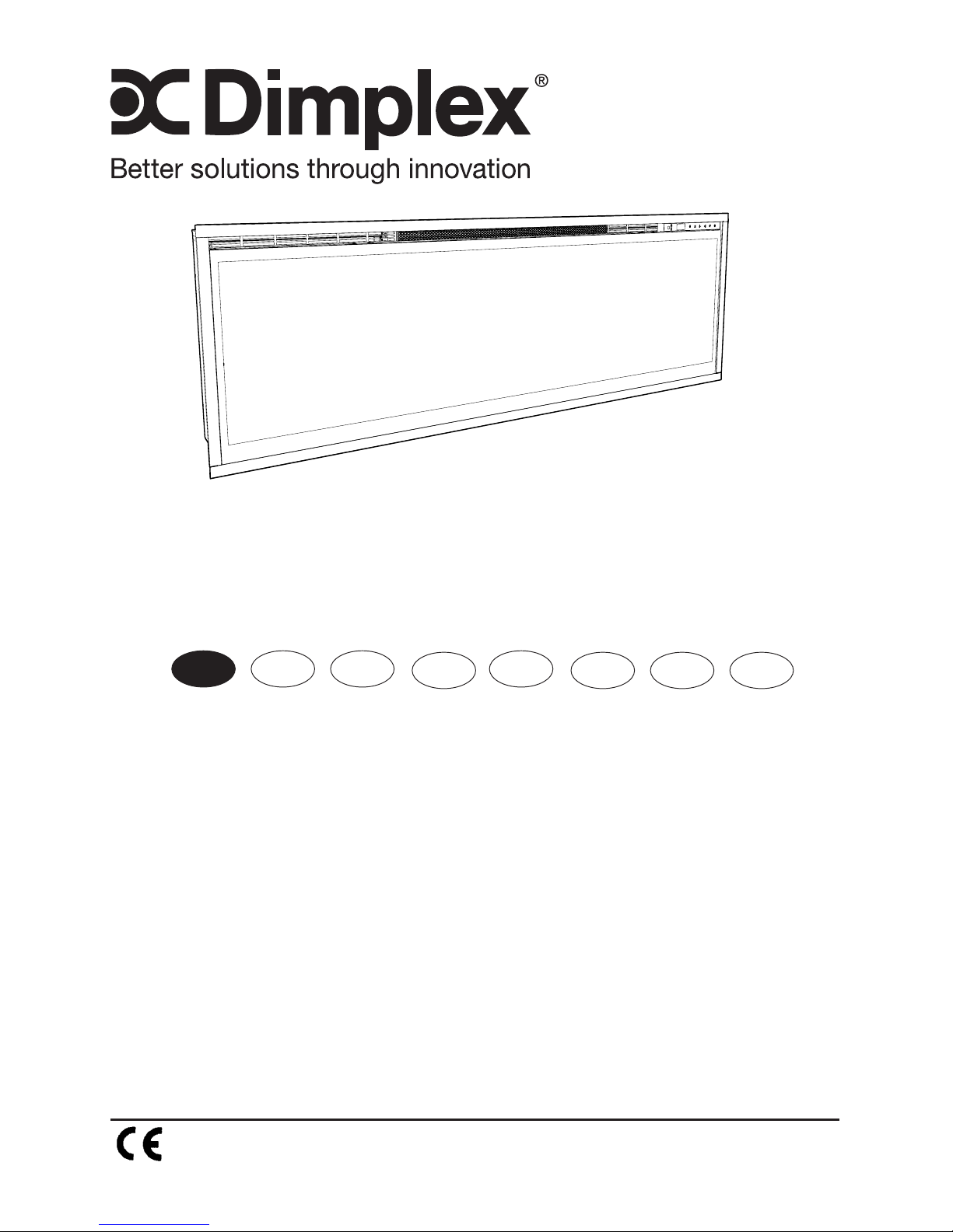
Ignite 50" / XLF50-EU
Ignite 74" / XLF74-EU
Ignite 100" / XLF100-EU
8/53801/0 Iss 3
OCN 10918
The product complies with the European Safety Standards and the European Standard Electromagnetic
Compatibility (EMC). These cover the essential requirements of EEC Directives
EN DE NL
FR
RO
IT PL ES
EN : This product is only suitable for well insulated rooms or occasional use. DE :
Dieses Produkt ist nur für gut isolierte Bereiche oder gelegentliche Verwendung
geeignet. FR : Ce produit convient uniquement à des endroits bien isolés ou pour un
usage occasionnel. IT : Questo prodotto è adatto solo per spazi ben isolati o per uso
occasionale. ES : Este producto sólo es adecuado para espacios bien aislados o un
uso ocasional. NL : Dit product is uitsluitend geschikt voor goed geïsoleerde ruimten
of voor sporadisch gebruik. PL : Produkt ten jest odpowiedni wyłącznie do dobrze
odizolowanych miejsc lub do okazjonalnego użytku. NO : Dette produktet egner seg
kun for godt isolerte rom eller sporadisk bruk. RO : Acest produs este adecvat exclusiv
spaţiilor bine ventilate sau utilizării ocazionale. CZ : Tento výrobek je vhodný pouze do
dobře izolovaných prostor nebo k příležitostnému použití. DK : Dette produkt er kun
egnet til velisolerede rum eller lejlighedsvis brug. PT : Este produto somente é adequado
para espaços bem isolados ou uso ocasional. SE : Denna produkt är endast avsedd för
välisolerade utrymmen eller tillfällig användning. FI : Tämä tuote soveltuu ainoastaan
hyvin eristettyihin tiloihin tai satunnaiseen käyttöön. SK : Tento výrobok je vhodný len pre
dobre izolované priestory alebo na občasné použitie. SI : Ta izdelek je primeren le za
dobro izolirane prostore ali za občasno uporabo. HR : Ovaj proizvod je pogodan samo
za dobro izolirane prostore ili povremenu upotrebu. HU : Ez a termék csak jól szigetelt
terekhez vagy eseti használatra alkalmas. SV : Denna produkt är endast lämplig för
användning i väl isolerade utrymmen eller enstaka användning.
Page 2
2
Table of Contents
Always use a qualied technician or
service agency to repair this replace.
!
NOTE: Procedures and tech-
niques that are considered important
enough to emphasize.
CAUTION: Procedures and tech-
niques which, if not carefully followed,
will result in damage to the equipment.
WARNING: Procedures and
techniques which, if not carefully
followed, will expose the user to
the risk of re, serious injury, or
death.
Welcome & Congratulations ..................3
IMPORTANT INSTRUCTIONS ..................4
Quick Reference Guide ......................6
Fireplace Installation ........................ 7
Operation ................................ 11
Maintenance .............................15
Page 3
3
Welcome & Congratulations
Thank you and congratulations for purchasing an electric replace from
Dimplex. Please take note of the location of the Model & Serial for this
product it is important to be able to locate it in the event of requiring
technical support.
Model and Serial
Number Label
Please carefully read and save these instructions.
CAUTION: Read all instructions and warnings carefully before
starting installation. Failure to follow these instructions may result in
a possible electric shock, re hazard and will void the warranty.
Page 4

4
Important Safety Advice
When using electrical appliances, basic precautions should
be followed to reduce the risk of re, electric shock, and
injury to persons, including the following:
If the appliance is damaged, check immediately with the
supplier before installation and operation.
Do not use this appliance in the immediate surroundings
of a bath, shower or swimming pool.
Do not use outdoors.
This appliance must not be located immediately above or
below a xed socket outlet or connection box.
WARNING: The appliance carries the Warning Symbol
indicating that it must not be covered or has a Do not cover
label. Do not cover or obstruct in any way the heat outlet
grille located at the top of the appliance overheating will
result if the appliance is accidentally covered. Do not place
material or garments on the appliance, or obstruct the air
circulation around the appliance, for instance by curtains
or furniture, as this could cause overheating and a re risk.
In the event of a fault unplug the heater. Unplug the
appliance when not required for long periods.The supply
cord must be placed on the right hand side of the heater
away from the heat outlet underneath the appliance.
Although this appliance complies with safety standards,
we do not recommend its use on deep pile carpets or on
long hair type of rugs.
This appliance can be used by children aged from 8 years
and above and persons with reduced physical, sensory or
mental capabilities or lack of experinence and knowledge if
they have been given supervision or instruction concerning
use of the appliance in a safe way and understand the
hazards involved. Children shall not play with the appliance.
Cleaning and user maintaince shall not be made by children
IMPORTANT INSTRUCTIONS
Page 5
5
SAVE THESE INSTRUCTIONS
without supervision.
Children of less than 3 years should be kept away unless
continuously supervised. Children aged from 3 years and
less than 8 years shall only switch on/off the appliance
provided that it has been placed or installed in its intended
normal operating position and they have been given
supervision or instruction concerning use of the appliance
in a safe way and understanding the hazards involved.
Children aged from 3 years and less than 8 years shall
not plug in, regulate and clean the appliance or perform
user maintaince.
The appliance must be positioned so that the plug is
accessible.
If the supply cord is damaged it must be replaced by the
manufacturer or service agent or similarly qualied person
in order to avoid a hazard.
CAUTION: In order to avoid a hazard due to inadvertent
resetting of the thermal cut-out, this appliance must not be
supplied through an external switching device, such as a
timer, or connected to a circuit that is regularly switched
on and off by the utility.
CAUTION - Some parts of this product can become very
hot and cause burns. Particular attention has to be given
where children and vulnerable people are present.
CAUTION
RISK OF ELECTRIC SHOCK
DO NOT OPEN
NO USER-SERVICABLE PARTS INSIDE
IMPORTANT INSTRUCTIONS
Page 6
6
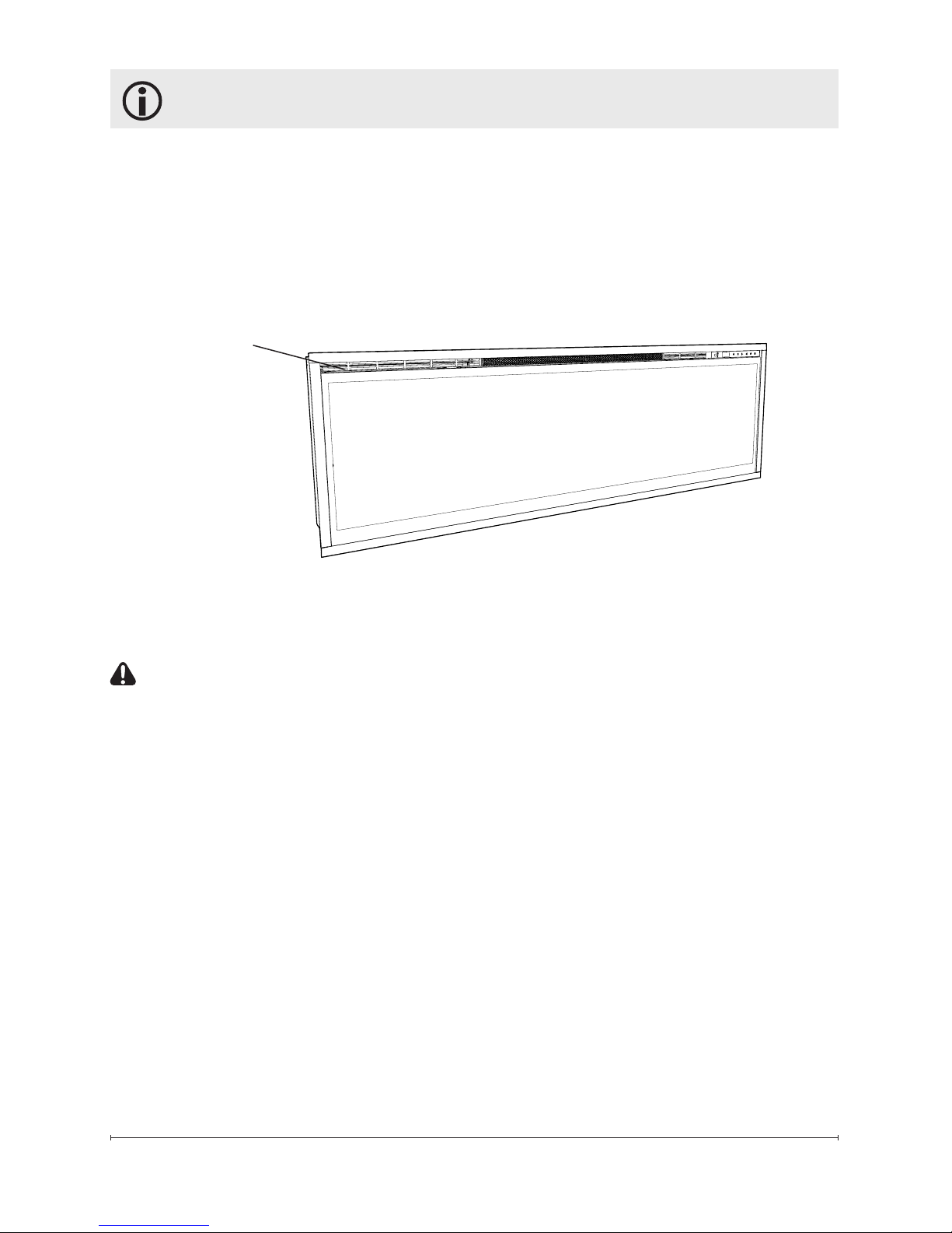
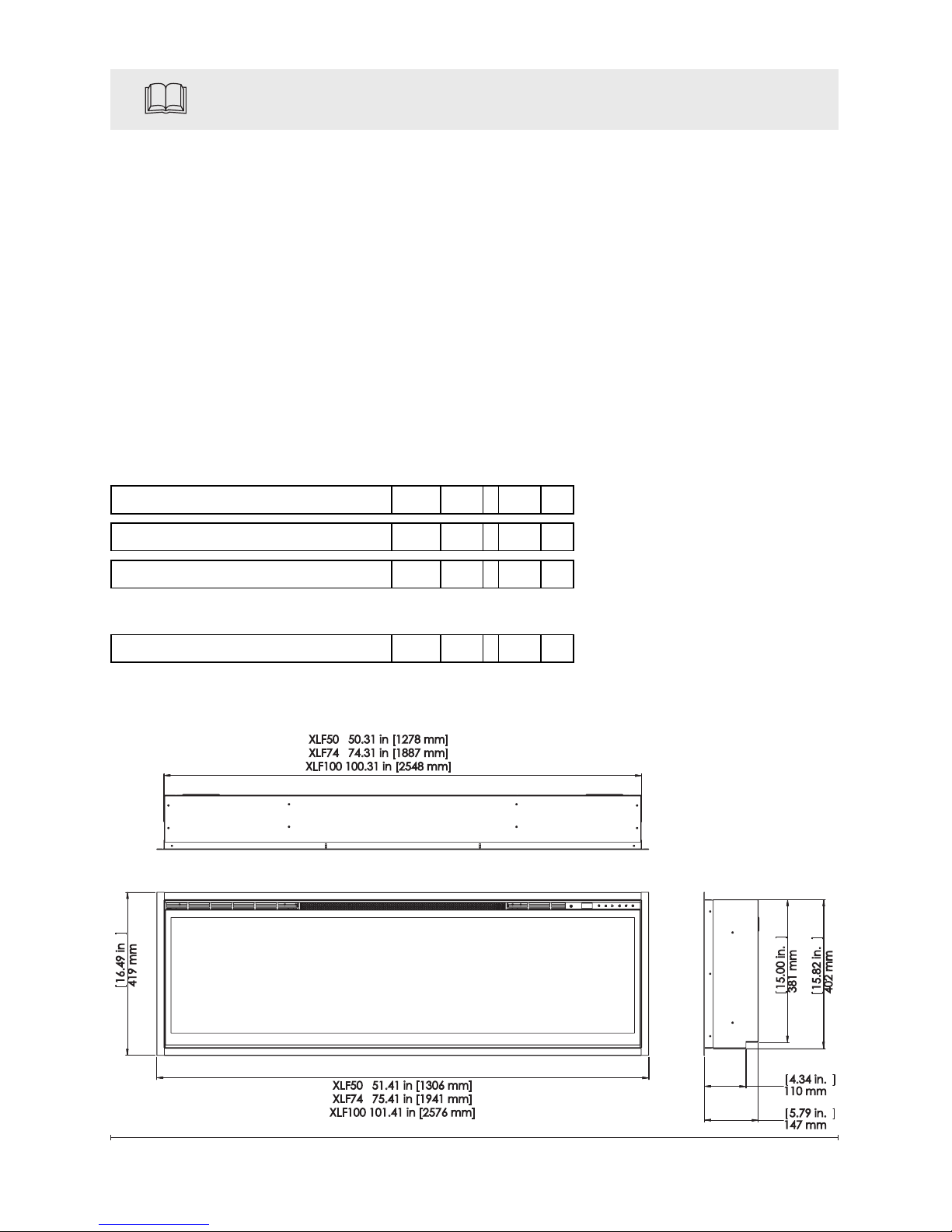
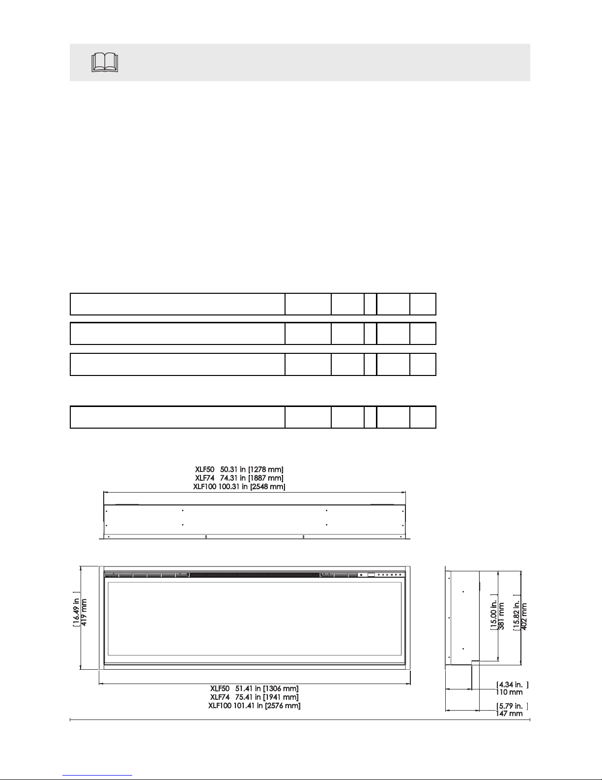
Quick Reference Guide
Figure 1
1. The electrical information
regarding your electric replace
can be found on the rating label
located on the top of the unit.
2. If you have any technical
questions or concerns
regarding the operation of your
electric replace, or require
service contact the relavent
customer service as listed on
your warrenty card.
3. For dimensions of your
replace, refer to Figure 1.
16.49 in
419 mm
15.82 in.
402 mm
15.00 in.
381 mm
5.79 in.
147 mm
4.34 in.
110 mm
XLF50 50.31 in [1278 mm]
XLF74 74.31 in [1887 mm]
XLF100 100.31 in [2548 mm]
XLF50 51.41 in [1306 mm]
XLF74 75.41 in [1941 mm]
XLF100 101.41 in [2576 mm]
Model No: XLF50-EU, XLF74-EU, XLF100-EU
Heat Output 230V 240V
Nominal Heat Output P
Nom
1.6 - 1.6 kW
Minimum Heat Output P
min
- - - kW
Maximum Continous Heat Output P
max,c
1.6 - 1.6 kW
Auxiliary Electricity Consumption
In Standby mode el SB0.47 - 0.49 W
Technical Information
with electronic room temperature control
Page 7
7
CAUTION: Ensure installation
does not allow replace to be in
direct contact with building vapor
barrier or insulation and meets all
local building code.
!
NOTE: A dedicated, properly
fused 13 Amp circuit is required,
rated for the appropriate voltage
(230-240V).
WARNING: Construction
and wiring must comply with
local building codes and other
applicable regulations to reduce
the risk of re, electric shock
and injury to persons.
WARNING: To reduce the risk
of re, electric shock or injury to
persons, always use a licensed
electrician.
WARNING: To reduce the risk of
re, do not store or use gasoline or
other ammable vapors or liquids in
the vicinity of the heater.
1. Select a location that is not
susceptible to moisture and is
away from drapes, furniture and
high trafc.
2. Unpack the replace and
hardware from the box.
!
NOTE: Leave the front glass
and partially reective glass,
safely, in the box until the time you
Fireplace Installation
are ready to install it.
3. Store the replace in a safe,
dry and dust free location until
you are ready to install the
replace.
Installation
CAUTION: Two people will be
required for various steps of
this procedure.
This design of this unit allows three
options for installation: partial
recess, ush mounted or subsurface mounted.
CAUTION: Sub-surface
mounting should be limited to ½
in. (12 mm) to ensure adequate
air ow of heated air out of the
rebox area.
1. Prepare a wall with a framed
opening of 16 in. (40.6 cm)
high,
• XLF50 - 50 ⅝ in. (128.7 cm)
• XLF74 - 74 ⅝ in. (189.7 cm)
• XLF100 - 100 ⅝ in. (255.7
cm) wide, with a bottom sill
that is a minimum of 4 in.
(10.2 cm) deep. The sill can
be constructed to support the
front of the unit to allow the
power supply wires to easily
be run behind or ush with the
back of the unit and a pass thru
Page 8
8
Fireplace Installation
hole drilled for electrical wire
routing.
!
NOTE: It is recommended that
the bottom of the unit be mounted
between 30 in. (76.2 cm) and 40
in. (102 cm) from the ground to
maintain an optimized viewing
angle of the ame.
WARNING: Do not attempt to
wire your own new circuits. To reduce
the risk of re, electric shock or injury
to persons, always use a licensed
electrician.
WARNING: Ensure that the
circuit on which the replace is to
be installed has the power cut off
at the service panel until installation
is complete.
2. The unit is provided with an
installed ¾ in. (2.0 cm) trim.
Depending on the installation,
this trim can be removed by
removing the securing screws
and the 4 trim pieces.
3. Lift replace, from the bottom
and the handles located on the
back, and insert into opening to
the desired depth.
4. Using a bubble level (supplied)
ensure that the replace is level
within the framing. Adjust as
required.
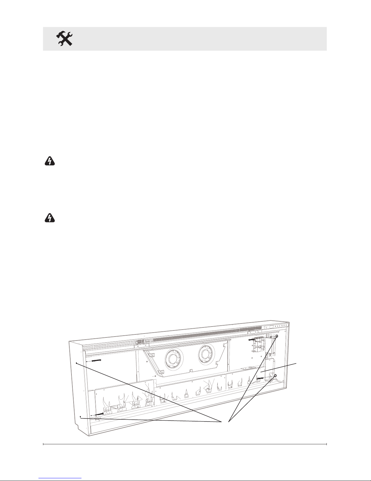
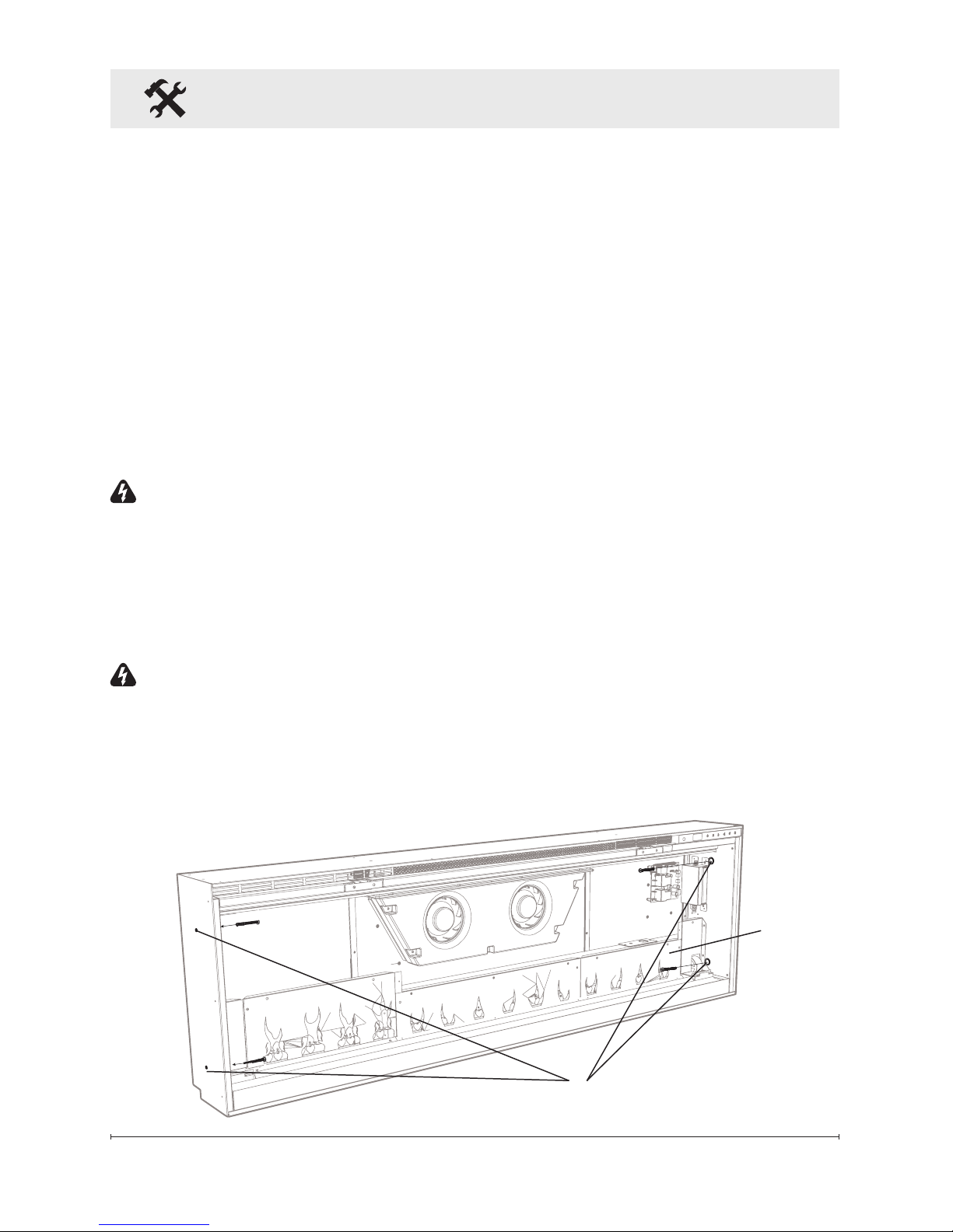
5. Drive four supplied mounting
screws through the four mounting
holes located on the inside
surface of the replace chassis,
into wall studs (Figure 2).
Figure 2
Mounting Holes
Flame
Panel
Page 9

9
Fireplace Installation
To prevent electrical shock this
unit is an electrical appliance
that is NOT watertight and must
be installed as to prevent water
from entering unit. This must be
installed away from showers, tubs,
etc. Never locate replace where
it may fall into a bathtub or other
water container.
Final Assembly
1. Locate and remove the
12 screws securing the partially
reflective glass bracket to
the unit, along the top of the
opening, and set bracket and
screws aside.
2. Remove the provided suction
cup from the inside cavity of
the unit (only for XLF74 and
XLF100 units).
3. Before installation ensure that
the front glass and the partially
reective glass are clean.
Particles can be removed by
dusting lightly with a clean dry
cloth. To remove ngerprints
or other marks, the glass
can be cleaned with a damp
cloth. Ensure that the glass
has completely dried before
installation.
4. Carefully secure the suction
cup to the partially reflective
glass, reflective side out, and
place into the openings on
either side of the unit.
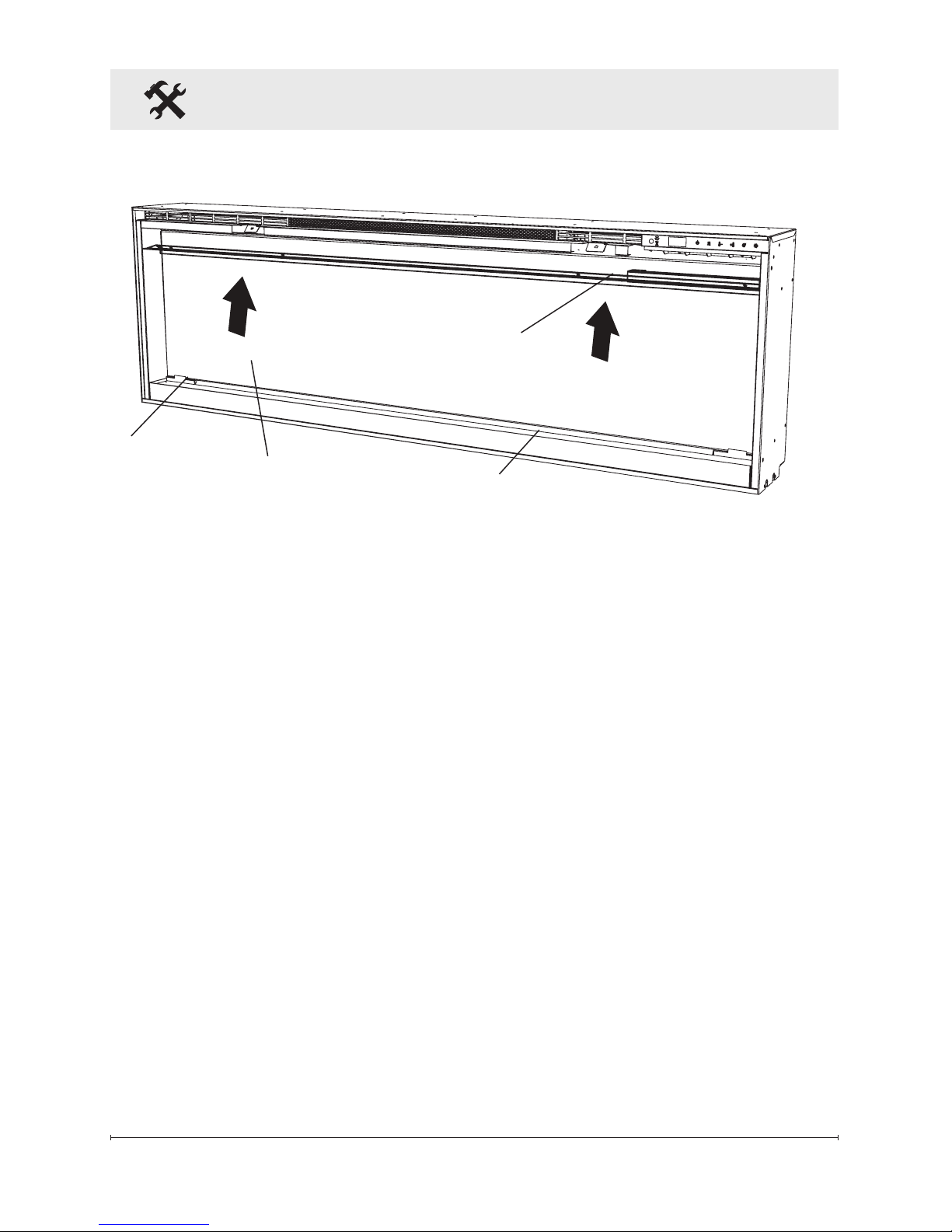
5. Tip the glass into the unit and
using the removed screws
secure the glass into the unit
with the provided bracket
(Figure 3). Remove the suction
cup.
Figure 3
Partially Reective Glass
Retaining Bracket
Media Tray
Glass Openings
Page 10
10
Fireplace Installation
6. Evenly space the large media
in the media tray along the back
of the media tray (for optimum
media effect), then carefully
pour and evenly distribute the
smaller media into the Media
Tray.
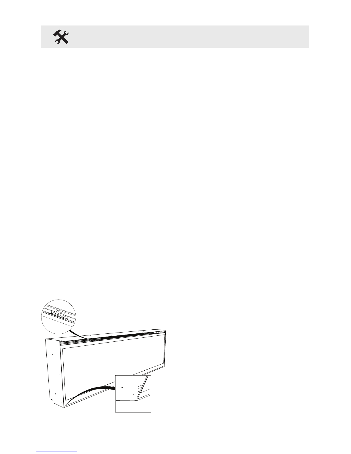
7. Carefully place the front glass
into the lip located at the bottom
of the opening of the firebox.
8. Tip the front glass into the
unit and secure using the
provided screws and Allen key.
(Figure 4).
!
NOTE: Ensure that the suction
cup and Allen key are kept
for any future maintenance or
service.
Figure 4
Fixed Wiring
In some jurisdictions this appliance
is supplied without a plug this is to
comply with the local regulations.
In such instances this appliance
must be installed by a suitabily
quailied installer and the means for
disconnection must be incorporated
in the xed wiring in accordance
with the local wiring rules.
Page 11
11
Operation
Remote Operation
The replace is supplied with an IR
multi-function remote control.
!
NOTE: To operate correctly, the
remote control must be pointed
towards the front of the unit.
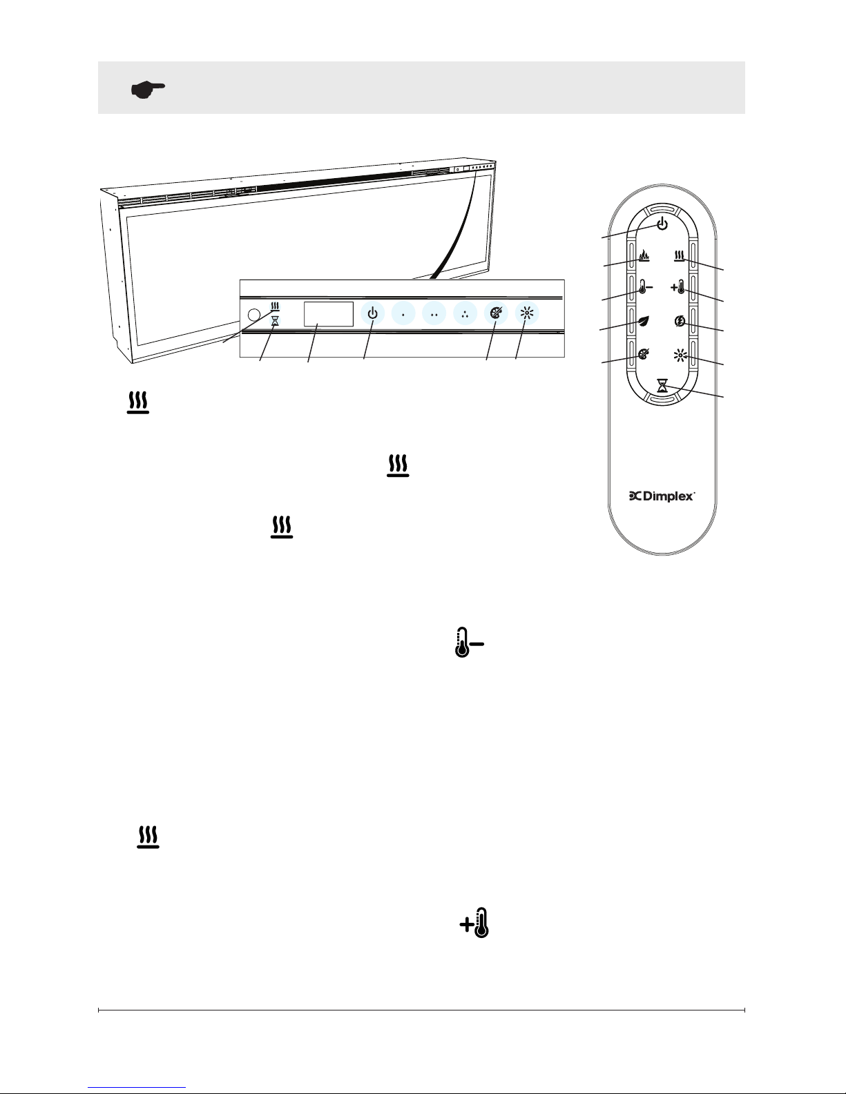
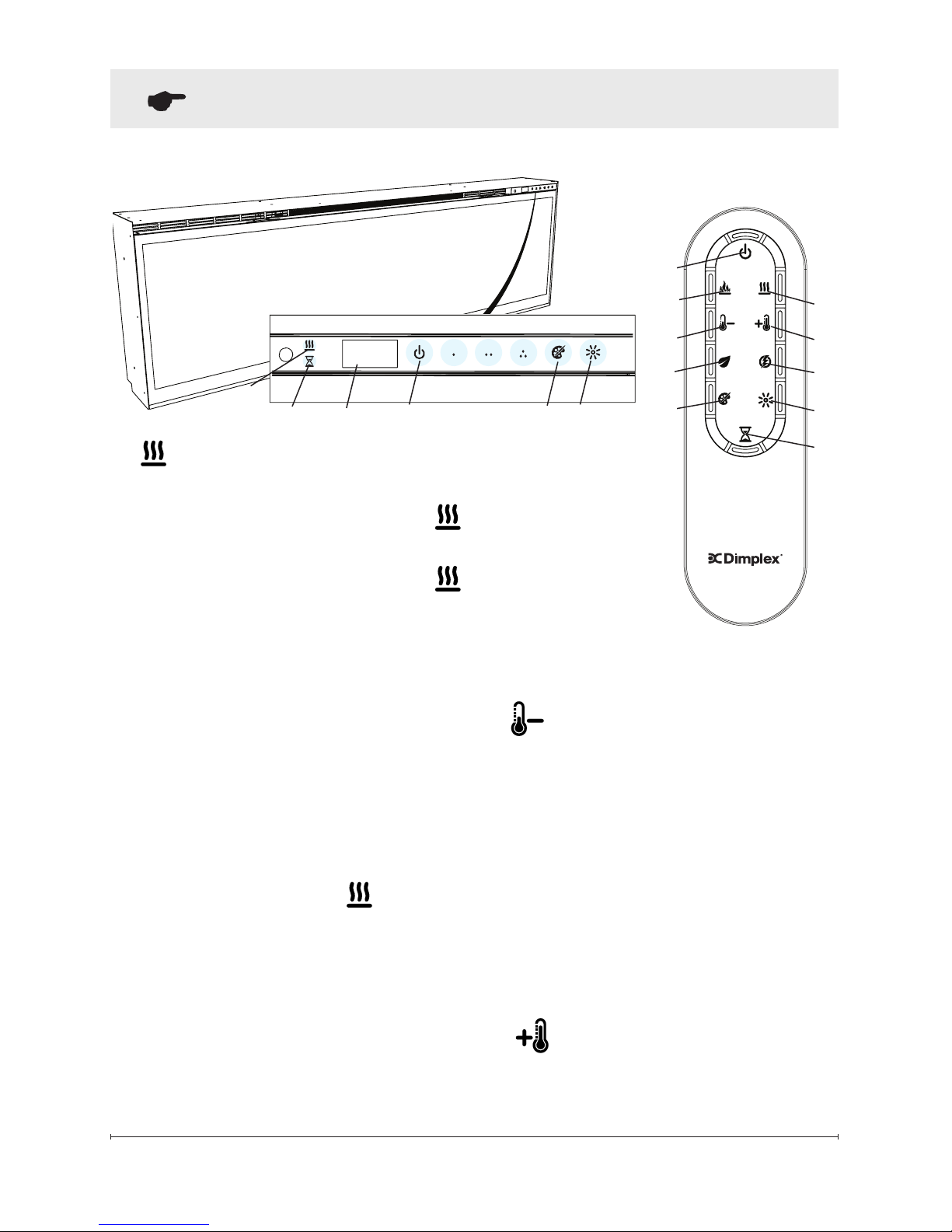
Controls
The unit can be controlled by
either the manual controls which
are located on the upper right of
the replace or the remote (Figure
5 & 6).
A. Standby
Turns the unit On and Off.
→ Activated by pressing the
Standby button on the remote
or the unit.
• The unit will turn On with the
same functions that it was set
to when it was turned Off and
the intake temperature will be
indicated on the Display.
!
NOTE: When any button is
pressed on the unit the intake
temperature will be displayed on
the Display for 7 seconds.
B. Flame Effects
Turns the Flame Effect On and Off.
→ Activated by pressing the
button on the remote.
General Operation
WARNING: This electric firebox
must be properly installed before it
is used.
This firebox operates with
Comfort$averTM technology,
which automatically adjusts the
fan speed and heater wattage to
safely and precisely match the
requirements of the room based on
the thermostat setting. The heater
operates such that once the room
reaches the set point, the fan and
heater will continuously run at a low
level, to maintain the desired room
temperature. If the temperature
in the room rises significantly, i.e.
sun coming through a window or a
central furnace turns on, the heater
will turn off and periodically turn
back on to circulate the air around
the unit, until the room temperature
drops and requires the heater to be
constantly on again.
!
NOTE: The unit is designed so
that the fan will run continuously
while the heater is on.
!
NOTE: The element retains
heat after shutdown, there is a built
in cool down period of 2 minute
before the fan shuts off completely,
when the heat function is turned
Off.
Page 12
12
Figure 5
A
Display
Figure 6
A
D
B
C
E
G
J
F
I
H
I
Operation
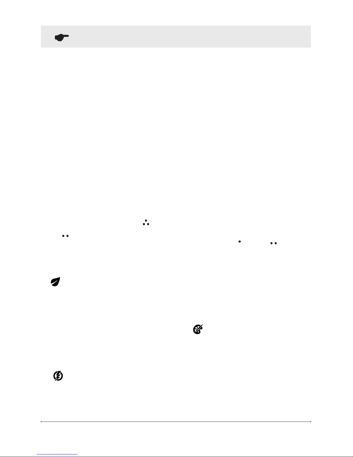
C. Heat ON/OFF
Turns the heater On and Off.
→ Activated by pressing the
button on the remote.
• Indicated by the
icon and the
setpoint temperature will ash
on the display, then the intake
temperature will be displayed
before turning off.
!
NOTE: After the heater is
switched off, there is a 2 minute fan
delay, where the fan will continue
running before turning off.
!
NOTE: The unit can be operated
in Heat Only Mode. When the unit
is only running with the heater,
the
icon will continuously be
displayed on the Display.
!
NOTE: The heater may emit
a slight, harmless odor when
rst used. This odor is a normal
condition caused by initial heating
of internal heater parts and will not
occur again.
D
Temperature Down
Decreases the temperature setting.
→ Adjusted by repeatedly pressing
the corresponding button on the
remote.*
• Indicated by setpoint temperature
on the Display decreasing and
the speed of the fan decreasing
to reduce the amount of heat
being projected into the room.**
E. Temperature Up
Increases the temperature setting.
C
J
H
Page 13
13
→ Activated and adjusted by
repeatedly pressing the
corresponding button on the
remote.
• Indicated by the heater running
at full heat, for a user set amount
of time, to quickly heat up a cold
room/space. The Heat Boost
can be set for a maximum of 20
minutes, in 5 minute increments.
Disable Heat
If desired, depending on the
season, the heater on the unit can
be disabled. The function of the
remaining controls will continue to
function as outlined in this manual.
Pressing the and buttons
on the unit at the same time and
holding for 2 seconds will disable
and enable the heater.
!
NOTE: When the heater has
been disabled and any of the heat
related functions are used, the
Display will indicate "---".
H. Color Themes
Different presets of lighting color
combinations are available in the
unit.
→ Changed by repeatedly pressing
the corresponding button on the
remote or the unit.
→ Adjusted by repeatedly pressing
the corresponding button on the
remote.*
• Indicated by the setpoint on
the Display increasing and the
speed of the fan increasing to
increase the amount of heat
being projected into the room.
* The rst time the button is pressed
the current temperature set point
will be displayed for 2 seconds.
** The temperature can be adjusted
from 5 °C to 37 °C (41 °F to
99 °F).
!
NOTE: Holding the and
the
buttons down for two
seconds, on the unit, will change
the temperature scale from °C to
°F, or vice versa.
F.
Eco Operation
Runs the heater in a reduced
wattage range when activated.
→ Adjusted by pressing the
corresponding button on the
remote when the heater is on.
• Indicated by the Display and a
reduced fan speed.
G.
Heat Boost
Turns the Heater Boost On and
Off. Runs the unit at the full rated
wattage.
Operation
Page 14
14
repeatedly, until the desired time
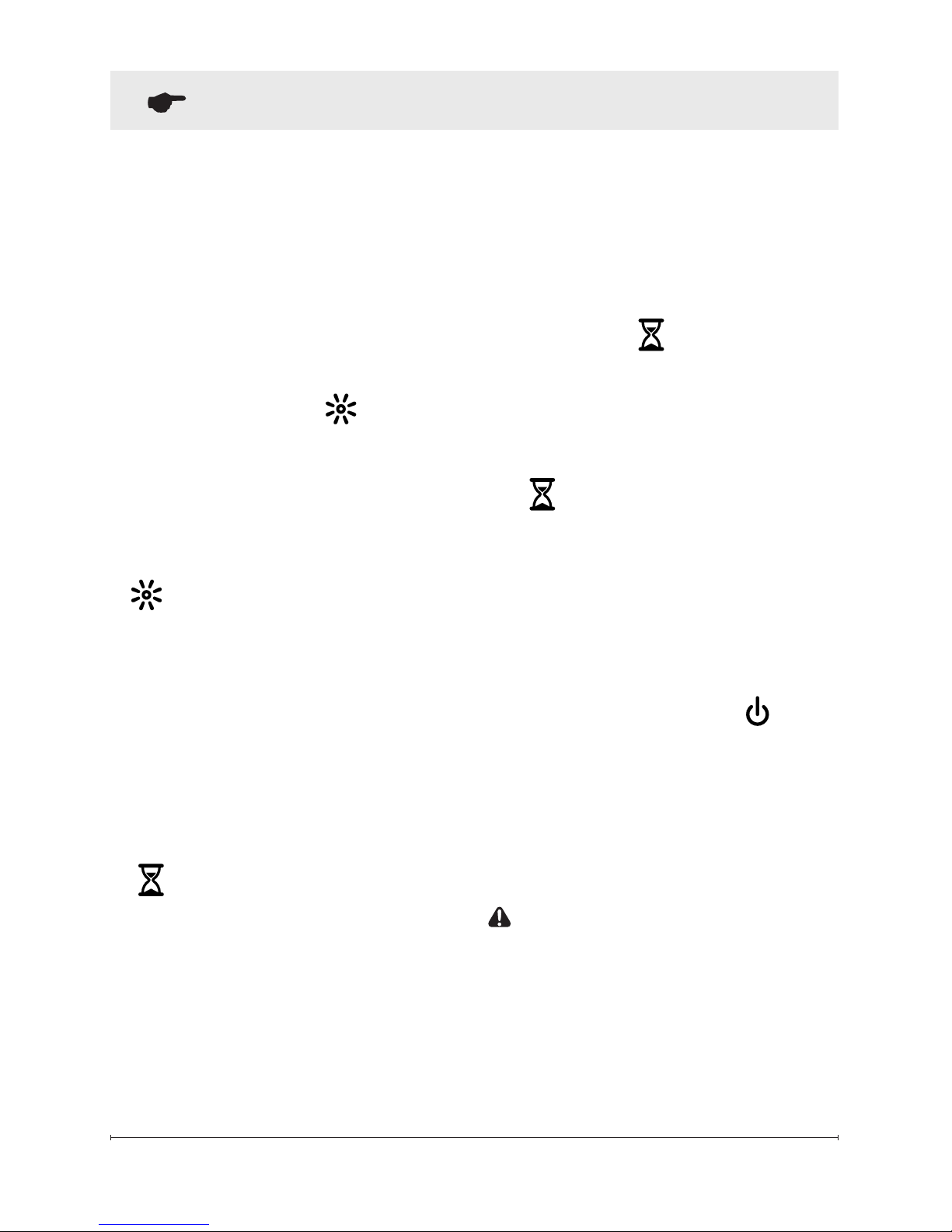
is displayed.
• The Display will display the
different times as it is adjusted.
Once the timer has begun,
pressing the button will display
the time remaining before the
unit turns Off.
!
NOTE: The Sleep Timer can be
cancelled at any time by pressing
the button repeatedly until the
sleep timer displays nothing.
Resetting the Temperature
Cutoff Switch
Should the heater overheat, an
automatic cut out will turn the whole
unit off and it will not come back on
without being reset. If the button
on the unit is pressed, Er2 will be
displayed on the unit. It can be
reset by turning the unit off at the
main disconnect panel and waiting
5 minutes before turning the unit
back on.
CAUTION: If you need to
continuously reset the heater, turn
the unit off at the main disconnect
panel and call technical support.
• Cycles through the different
preset light settings of the
unit, this includes different
combinations of colors of the
ame base and media lighting.
!
NOTE: Two of the themes in
the cycle are a prism where the
unit cycles through a variety of
colors. Pressing the stops the
cycling and holds the unit on the
preferred color, indicated by a solid
circle. When the unit is on prism,
and is cycling through the colors,
a rotating circle will be displayed.
I.
Brightness
Changes the Brightness of the
lights in the unit.
→ Adjusted by repeatedly pressing
the corresponding button on the
remote or the unit.
• Indicated by the second digit on
the Display changing to show:
"H" (high), and "L" (low).
J. Sleep Timer
The Sleep Timer can be set to
automatically shut off the replace
after a preset time (from 30 minutes
to 8 hours).
→ To set the timer press the
timer button on the remote,
Operation
Page 15

15
Operation
Remote Control Battery
Replacement
To replace the Battery:
1. Slide battery cover open on the
remote control.
2. Correctly install one 3 Volt
(CR2032 [longer life] or
CR2025) Battery in the
battery holder.
3. Close the battery cover.
Battery must be recycled or
disposed of properly. Check with
your Local Authority or Retailer
for recycling advice in your area.
Maintenance
WARNING: Disconnect power
and allow heater to cool before
attempting any maintenance or
cleaning to reduce the risk of
re, electric shock or damage to
persons.
!
NOTE: The replace
should not be operated with an
accumulation of dust or dirt on or in
the unit, as this can cause a build
up of heat and eventual damage.
For this reason the heater must
be inspected regularly, depending
upon conditions and at a minimum
yearly intervals.
Partially Reective Glass
Cleaning
The partially reective glass is
cleaned in the factory during
the assembly operation. During
shipment, installation, handling,
etc., the partially reective glass
may collect dust particles; these
can be removed by dusting lightly
with a clean dry cloth.
To remove ngerprints or other
marks, the partially reective
glass can be cleaned with a damp
cloth. The partially reective glass
should be completely dried with
a lint free cloth to prevent water
spots. To prevent scratching, do
not use abrasive cleaners.
Page 16
16
Fireplace Surface Cleaning
Use only a damp cloth to clean
painted surfaces of the replace.
Do not use abrasive cleaners.
Recycling
For electrical products
sold within the European
Community. At the end
of the electrical products
useful life it should not be
disposed of with household waste.
Please recycle where facilities exist.
Check with your Local Authority or
retailer for recycling advice in your
country.
After Sales Service
Your product is guaranteed for one
year from the date of purchase.
Within this period, we undertake
to repair or exchange this product
free of charge (excluding lamps &
subject to availability) provided it
has been installed and operated in
accordance with these instructions.
Your rights under this guarantee are
additional to your statutory rights,
which in turn are not affected by
this guarantee.
Should you require after sales
service you should contact our
customer services the contact
number is located on your warrenty
card. It would assist us if you can
quote the model number, series,
date of purchase, and nature of the
fault at the time of your call. The
customer services help desk will
also be able to advise you should
you need to purchase any spares.
Please do not return a faulty product
to us in the rst instance as this may
result in loss or damage and delay
in providing you with a satisfactory
service.
Please retain your receipt as proof
of purchase.
Maintenance
Page 17
17
Inhaltsverzeichnis
Beauftragen Sie stets einen
qualizierten Techniker oder
eine Wartungsagentur,um
diesen Kamin zu reparieren.
!
HINWEIS: Prozesse und
Verfahren, die als wichtig erachtet
und deshalb speziell hervorgehoben
werden.
VORSICHT: Prozesse und
Verfahren, die zu einer Beschädigung
der Ausrüstung führen, wenn sie nicht
genau beachtet werden.
WARNUNG: Prozesse und
Verfahren, die ein Brandrisiko
darstellen und beim Benutzer
zu ernsthaften Verletzungen
mit möglicher Todesfolge führen
können, wenn sie nicht genau
beachtet werden.
Willkommen und herzlichen Glückwunsch ......18
WICHTIGE ANWEISUNGEN ..................19
Kurzanleitung .............................21
Montage des Kamins ......................22
Betrieb ..................................26
Wartung .................................30
DE
Page 18

18
Willkommen und herzlichen Glückwunsch
Danke und herzlichen Glückwunsch, dass Sie sich für einen Elektrokamin
von Dimplex entschieden haben. Bitte beachten Sie, wo Modell- und
Seriennummer dieses Produkts angegeben werden. Sie müssen diese
nden können, falls Sie technische Unterstützung benötigen sollten.
Bitte lesen Sie diese Anleitung sorgfältig durch
und bewahren Sie sie sicher auf.
VORSICHT: Lesen Sie alle Anweisungen und Warnhinweise
vor der Montage sorgfältig durch. Bei einer Nichtbeachtung dieser
Anweisungen kann es zu Stromschlägen oder Bränden kommen,
unddie Garantie wird ungültig.
Modell- und
Seriennummernschild
Page 19
19
Wichtige Sicherheitshinweise
Bei der Benutzung von elektrischen Anwendungen sollten die
grundlegenden Sicherheitsmaßnahmen befolgt werden, um
das Risiko für Feuer, Stromschlag oder die Verletzung von
Personen einschließlich Folgendem zu vermeiden:
Ist das Gerät beschädigt, sprechen Sie unverzüglich mit dem
Zulieferer vor der Montage und Inbetriebnahme.
Dieses Gerät nicht in der unmittelbaren Nähe eines Bades,
einer Dusche oder eines Schwimmbeckens benutzen.
Nicht draußen benutzen.
Platzieren Sie dieses Gerät nicht direkt ober- oder unterhalb
einer Steckdose oder eines Anschlusskastens.
WARNUNG : Das Gerät ist mit einem Warnsymbol versehen,
welches anzeigt, dass das Gerät nicht abgedeckt werden darf,
oder mit einem Etikett mit der Aufschrift „Nicht abdecken“.
Das Gitter des Wärmeabzugs oben am Gerät darf nicht
abgedeckt oder blockiert werden. Das Gerät kann ansonsten
überhitzen. Keine Materialien oder Textilien auf das Gerät
legen oder den Luftuss um das Gerät herum beeinträchtigen,
beispielsweise durch Vorhänge oder Möbelstücke, da dies
zu einer Überhitzung des Geräts führen und Brandgefahr
verursachen kann.
Ziehen Sie im Fall einer Störung des Geräts den Netzstecker.
Ziehen Sie den Netzstecker auch, wenn das Gerät für einen
längeren Zeitraum nicht genutzt wird. Das Stromkabel ist
auf der rechten Seite des Geräts, weg vom Wärmeabzug
unterhalb des Geräts zu platzieren.
Obwohl dieses Gerät den Sicherheitsstandards entspricht,
empfehlen wir, das Gerät nicht auf Hochor-Teppichen zu
benutzen oder auf Teppichen mit langen Fasern.
Dieses Gerät darf von Kindern ab 8 Jahren betrieben werden
sowie von Personen, die verminderte körperliche, sensorische
oder geistige Fähigkeiten haben oder keine Erfahrung oder
Wissen haben, wenn sie die Aufsicht für den sicheren Betrieb
eines Gerätes oder Anweisungen erhalten haben und die
potentiellen Gefahren verstehen. Kinder dürfen nicht mit dem
WICHTIGE ANWEISUNGEN
Page 20
20
BITTE BEWAHREN SIE DIESE
ANWEISUNGEN SICHER AUF
Gerät spielen. Die Reinigung und Wartung darf nicht von
Kindern ohne Aufsicht erfolgen.
Kinder unter 3 Jahren sollten von dem Gerät ferngehalten
werden, es sei denn, sie sind stets beaufsichtigt. Kinder
ab 3 Jahre und weniger als 8 Jahre dürfen das Gerät nur
an- und ausschalten, wenn es in seiner vorgesehenen
Betriebsposition aufgestellt und montiert wurde und wenn
sie die Aufsicht für den sicheren Betrieb eines Gerätes oder
Anweisungen erhalten haben und die potentiellen Gefahren
verstehen. Kinder ab 3 Jahren und unter 8 Jahren dürfen
das Gerät nicht einstecken, regulieren oder reinigen oder
Wartungsarbeiten vornehmen.
Das Gerät muss so aufgestellt werden, dass der Stecker
zugänglich ist.
Wenn das Stromkabel beschädigt ist, muss es durch den
Hersteller oder Dienstleister oder eine ähnlich qualizierte
Person ersetzt werden, um Gefahren zu vermeiden.
VORSICHT: Um Gefahren aufgrund unbeabsichtigter
Zurücksetzung des Thermoauslösers zu vermeiden, darf
das Gerät nicht an ein externes Schaltgerät angeschlossen
werden, wie etwa ein Zeitschaltgerät oder an einen
Stromkreis, der regelmäßig von der Stromversorgung an- und
ausgeschaltet wird.
VORSICHT - Einige Teile dieses Produkts können sehr
heiß werden und Verbrennungen verursachen. Besondere
Vorsicht ist bei der Anwesenheit von Kindern und verletzlichen
Personen erforderlich.
VORSICHT
STROMSCHLAGGEFAHR
NICHT ÖFFNEN
ES BEFINDEN SICH KEINE TEILE IM GERÄT, DIE VOM
BENUTZER GEWARTET WERDEN KÖNNEN
WICHTIGE ANWEISUNGEN
Page 21
21
Kurzanleitung
Abbildung 1
1. Die elektrischen Informationen
über Ihren Elektrokamin nden
Sie auf dem Typenschild oben
auf dem Gerät.
2. Sollten Sie technische Fragen
oder Bedenken hinsichtlich des
Betriebs Ihres Elektrokamins
haben oder eine Wartung
benötigen, kontaktieren Sie den
entsprechenden Kundenservice,
der auf Ihrer Garantiekarte
angegeben ist.
3. Die Maße Ihres Kamins nden
Sie in Abbildung 1.
16.49 in
419 mm
15.82 in.
402 mm
15.00 in.
381 mm
5.79 in.
147 mm
4.34 in.
110 mm
XLF50 50.31 in [1278 mm]
XLF74 74.31 in [1887 mm]
XLF100 100.31 in [2548 mm]
XLF50 51.41 in [1306 mm]
XLF74 75.41 in [1941 mm]
XLF100 101.41 in [2576 mm]
Modellnr.: XLF50-EU, XLF74-EU, XLF100-EU
Wärmeleistung 230V 240V
Minimale Wärmeleistung P
Min
1.6 - 1.6 kW
Minimale Wärmeleistung P
Min
- - - kW
Maximale kontinuierliche Wärmeleistung P
max, c
1.6 - 1.6 kW
Nebenelektrizitätsverbrauch
In den Standby-Modus SB
SB
0.47 - 0.49 e
Technische Informationen
Mit elektronischer Raumtemperaturkontrolle
Page 22
22
VORSICHT: Gehen Sie bei der
Montage sicher, dass der Kamin
nicht direkt mit der Dampfsperre
oder Isolierung des Gebäudes in
Kontakt kommt und alle örtlichen
Bauauagen einhält.
!
HINWEIS: Es ist ein dedizierter,
korrekt abgesicherter 13 A
Anschluss mit geeigneter
Nennspannung (230-240 V)
erforderlich.
VORSICHT: Bau und Verkabelung
müssen den örtlichen
Bauvorschriften und anderen
relevanten Bestimmungen
entsprechen, um das Brandrisiko
sowie eine Stromschlag- und
Verletzungsgefahr möglichst
gering zu halten.
VORSICHT: Um das Risiko eines
Brandes, von elektrischem Schlag
oder die Verletzungsgefahr für
Menschen zu verringern, setzen Sie
einen ausgebildeten Elektriker ein.
VORSICHT: Um die Brandgefahr
zu senken, sollten Sie kein Benzin
oder andere entammbare Dämpfe
oder Flüssigkeiten in der Nähe des
Ofens aufbewahren oder nutzen.
1. Wählen Sie einen Standort, der
keiner Feuchtigkeit ausgesetzt ist
und ausreichend von Vorhängen,
Möbeln und vermehrtem
Vorbeilaufen entfernt ist.
2. Entnehmen Sie den Kamin und
die Hardware aus der Kiste.
Montage des Kamins
!
HINWEIS: Lassen Sie das
Frontglas und das teils reektierende
Glas sicher in der Kiste, bis es zu
montieren ist.
3. Lagern Sie den Kamin an
einem sicheren, trockenen und
staubfreien Ort, bis Sie ihn
montieren möchten.
Montage
VORSICHT: Es sind zwei
Personen notwendig, um
einige Schritte des Verfahrens
auszuführen.
Dieses Design dieses Geräts bietet
drei Montagemöglichkeiten: teilweise
abgesetzt, bündig montiert oder
unter der Wand montiert.
VORSICHT: Einbau unter
der Wand sollte nicht mehr
als ½ (12 mm) betragen, um
den notwendigen Luftstrom
der erhitzten Luft aus dem
Bereich der Feuerkammer zu
garantieren.
1. Bereiten Sie die Wand vor mit
einer umrahmten Öffnung von
16 in. (40,6 cm) Höhe,
• XLF50 - 50 ⅝ (128,7 cm)
• XLF74 - 74 ⅝ (189,7 cm)
• XLF100 - 100 ⅝ (225,7 cm)
Breite, mit einer unteren Bank mit
mindestens 4 in. (10,2 cm) Tiefe.
Diese Bank kann so konstruiert
werden, dass sie das Gerät vorne
stützt und die Kabel einfach
Page 23
23
Montage des Kamins
dahinter laufen lässt, oder dass
sie bündig an der Hinterseite
des Geräts sitzt. In diesem Fall
muss ein Loch gebohrt werden,
um die elektrischen Leitungen
hindurchzuführen.
!
HINWEIS: Es wird empfohlen,
den Boden des Geräts zwischen
30 in. (76,2 cm) und 40 in. (102 cm)
über dem Boden anzubringen, um
einen optimalen Winkel für die Sicht
der Flamme zu schaffen.
VORSICHT: Versuchen Sie nicht,
eigene neue Schaltkreise zu verkabeln.
Um das Risiko eines Brandes,
von elektrischem Schlag oder die
Verletzungsgefahr für Menschen
zu verringern, setzen Sie einen
ausgebildeten Elektriker ein.
VORSICHT: Stellen Sie sicher,
dass der Stromkreislauf, an den der
Kamin angeschlossen werden soll,
am Service Panel ausgestellt ist, bis
dass die Montage abgeschlossen ist.
2. Das Gerät wird mit einer
eingebauten ¾ Zierleiste von
(2,0 cm) geliefert. Je nach
Montageart kann diese Zierleiste
abgebaut werden, indem die
Sicherungsschrauben und die
vier Zierteile entfernt werden.
3. Heben Sie den Kamin, indem
Sie ihn von unten und mithilfe
der Griffe auf der Rückseite
anfassen, und setzen Sie ihn
bis zur gewünschten Tiefe in die
Öffnung ein.
4. Nutzen Sie eine Wasserwaage
(mitgeliefert), um sicherzugehen,
dass der Kamin gerade in
den Rahmen eingepasst wird.
Anpassen, falls erforderlich.
5. Führen Sie die vier mitgelieferten
Montageschrauben durch die vier
Montagelöcher an der inneren
Oberäche des Kamingehäuses
in die Wandstifte (Abbildung 2).
Abbildung 2
Montagelöcher
Reektorplatte
Page 24
24
Montage des Kamins
Um Stromschläge zu vermeiden,
handelt es sich bei diesem Gerät
um ein NICHT wasserdichtes
Elektrogerät, und es muss so
montiert werden, dass kein Wasser
in das Gerät eintreten kann. Das
Gerät muss außer Reichweite
von Duschen, Badewannen usw.
montiert werden. Bauen Sie den
Kamin an keinem Ort ein, von wo
er in die Badewanne oder einen
anderen Wasserbehälter fallen
kann.
Endmontage
1. Finden und entfernen Sie die 12
Schrauben, die die Halterung
des teils reflektierenden Glases
mit dem Gerät verbinden, am
oberen Rand der Öffnung.
Legen Sie die Halterung und die
Schrauben beiseite.
2. Entnehmen Sie den
mitgelieferten Saugnapf aus
dem Hohlraum im Inneren des
Geräts (nur bei den Geräten
XLF74 und XLF100).
3. Gehen Sie vor der Montage
sicher, dass das Frontglas und
das Teils reektierende Glas
sauber sind. Partikel können
entfernt werden, indem sanft
mit einem sauberen, trockenen
Tuch darüber gewischt wird.
Verwenden Sie ein feuchtes
Tuch, um Fingerabdrücke oder
andere Flecken auf dem Glas
zu entfernen. Versichern Sie
sich davon, dass das Glas
vollständig trocken ist, bevor Sie
es montieren.
4. Sichern Sie den Saugnapf
vorsichtig am teils reflektierenden
Glas, mit der reflektierenden
Seite nach außen, und führen
Sie es in die Öffnungen auf
beiden Seiten des Geräts ein.
Abbildung 3
Teils reektierendes Glas
Halterung
Medienschale
Glasöffnungen
Page 25

25
Montage des Kamins
5. Senken Sie das Glas in das Gerät
und nutzen Sie die entfernten
Schrauben, um das Glas mit
der beigefügten Halterung
an dem Gerät zu befestigen
(Abbildung 3). Entfernen Sie den
Saugnapf.
6. Verteilen Sie das größere
Medium in der Medienschale
entlang der hinteren Seite
der Medienschale (für einen
optimalen Medieneffekt).
Schütten und verteilen Sie dann
das kleinere Medium in die
Medienschale.
7. Stellen Sie das Frontglas
vorsichtig auf den Rand an der
unteren Seite der Öffnung der
Feuerkammer.
8. Senken Sie das Frontglas in
das Gerät und nutzen Sie die
beigefügten Schrauben und
Abbildung 4
den Inbusschlüssel, um es zu
befestigen. (Abbildung 4).
!
HINWEIS: Gehen Sie sicher,
dass der Saugnapf und der
Inbusschlüssel für eventuelle
zukünftige Wartungsarbeiten
aufbewahrt werden.
Feste Verkabelung
In einigen Ländern wird das Gerät
ohne Netzstecker ausgeliefert,
um den lokalen Vorschriften zu
entsprechen. In einigen Fällen muss
dieses Gerät von entsprechend
qualiziertem Fachpersonal montiert
werden und in der Hausverkabelung
muss eine Trenneinrichtung unter
Einhaltung der geltenden Vorschriften
für den Anschluss von Elektrogeräten
vorgesehen werden.
Page 26
26
Betrieb
Fernsteuerung
Der Kamin wird mit einer IRFernbedienung, die mehrere
Funktionen umfasst, geliefert.
!
HINWEIS:
Damit die
Fernbedienung richtig funktioniert,
muss sie auf die Vorderseite des
Geräts gerichtet werden.
Steuerungen
Das Gerät kann entweder mithilfe
der manuellen Reglern am oberen
rechten Rand des Kamins oder
mithilfe der Fernbedienung gesteuert
werden (Abbildung 5 und 6).
A. Standby
Schaltet das Gerät An und Aus.
→ Wird durch Drücken der Standby-
Taste auf der Fernbedienung oder
am Gerät aktiviert.
• Das Gerät wird angeschaltet mit
den gleichen Funktionen, die beim
Abschalten eingestellt waren. Die
Eintrittstemperatur wird auf dem
Display angezeigt.
!
HINWEIS: Wenn irgendeine Taste
auf dem Gerät gedrückt wird, wird die
Eintrittstemperatur 7 Sekunden lang
auf dem Display angezeigt.
B. Flammeffekte
Schaltet den Flammeffekt An und
Aus.
→ Wird durch Drücken der Taste
auf der Fernbedienung aktiviert.
Allgemeiner Betrieb
VORSICHT: Diese Elektro-
Feuerkammer muss vor der Nutzung
korrekt montiert werden.
Diese Feuerkammer
funktioniert mit Comfort$averTM
Technologie, die automatisch die
Ventilatorengeschwindigkeit und
die Wattleistung der Heizung so
anpasst, dass sie sich sicher und
genau die Raumvoraussetzungen
auf Grundlage der ThermostatEinstellung anpassen. Die Heizung
funktioniert so, dass Ventilator und
Heizung kontinuierlich auf geringer
Stufe weiterlaufen, wenn eine
bestimmte Raumtemperatur erreicht
ist, um die gewünschte Temperatur
zu erhalten. Wenn die Temperatur
im Raum sich bedeutend erhöht,
z. B. weil die Sonne durchs Fenster
scheint oder sich die Zentralheizung
anschaltet, schaltet sich die Heizung
ab und regelmäßig wieder an, um
Luft im System zu bewegen, bis die
Raumtemperatur wieder fällt und die
Heizung wieder ständig funktioniert.
!
HINWEIS: Das Gerät ist so
konzipiert, dass der Ventilator
kontinuierlich läuft, während die
Heizung an ist.
!
HINWEIS: Das Gerät speichert
Hitze, wenn es abgeschaltet wird.
Wenn die Heizfunktion abgeschaltet
wird, gibt es eine Abkühlzeit von
2 Minuten, bevor der Ventilator
vollständig aus ist.
Page 27
27
Abbildung 5
A
H
Anzeige
Abbildung 6
A
D
B
C
E
G
J
F
I
H
I
Betrieb
C. Wärmefunktion AN / AUS
Schaltet die Heizung An und Aus.
→ Wird durch Drücken der Taste
auf der Fernbedienung aktiviert.
• Angezeigt durch das Symbol
und die Solltemperatur blinkt auf
dem Display. Vor dem Ausschalten
wird die Eintrittstemperatur
angezeigt.
!
HINWEIS: Nachdem die Heizung
ausgeschaltet wird, läuft der Ventilator
noch 2 Minuten weiter, bevor er sich
ausschaltet.
!
HINWEIS: Das Gerät kann im Nur
Heizen-Modus genutzt werden.
Wenn das Gerät nur als Heizung
funktioniert, wird das
Symbol
kontinuierlich auf dem Display
angezeigt.
!
HINWEIS: Beim Erstgebrauch
kann die Heizung einen leichten,
ungefährlichen Geruch abgeben.
Dieser Geruch ist normal und
entsteht durch das erste Erhitzen
der inneren Heizteile. Er wird nicht
wieder auftreten.
D
Geringere Temperatur
Verringert die Temperatureinstellung.
→ Durch wiederholtes Drücken
der jeweiligen Taste auf der
Fernbedienung angepasst.*
• Angezeigt durch die sich
verringernde Solltemperatur
auf dem Display und das
Langsamerwerden des Ventilators,
um die Hitze, die an den Raum
abgegeben wird, zu verringern.**
E. Höhere Temperatur
Erhöht die Temperatureinstellung.
J
Page 28
28
→ Durch wiederholtes Drücken
der jeweiligen Taste auf der
Fernbedienung aktiviert und
angepasst.
• Angezeigt durch die Heizung, die
für eine vom Nutzer bestimmte
Zeit auf höchster Temperatur läuft,
um einen kalten Raum schnell zu
heizen. Der Wärme-Boost kann
in 5-Minuten-Schritten für bis zu
20 Minuten eingeschaltet werden.
Wärme deaktivieren
Ja nach Jahreszeit kann auf Wunsch
die Heizung des Geräts deaktiviert
werden. Die Funktionen der übrigen
Kontrollen funktionieren weiterhin
wie in diesem Handbuch angegeben.
Durch Drücken der Tasten und
auf dem Gerät zur gleichen Zeit
für 2 Sekunden wird die Heizung
deaktiviert und aktiviert.
!
HINWEIS: Wenn die
Heizung deaktiviert wurde, und
wärmebezogene Funktionen benutzt
werden, zeigt das Display „---“ an.
H. Lichtfarbenauswahl
Mit dem Gerät sind
verschiedene Voreinstellungen
für Lichtfarbenkombinationen
verfügbar.
→ Wird durch wiederholtes Drücken
der betreffenden Taste auf der
Fernbedienung oder am Gerät
aktiviert.
→ Durch wiederholtes Drücken
der jeweiligen Taste auf der
Fernbedienung angepasst.*
• Angezeigt durch die sich
erhöhende Solltemperatur auf dem
Display und das Schnellerwerden
des Ventilators, um die Hitze, die
an den Raum abgegeben wird, zu
erhöhen.
* Beim ersten Drücken der Taste
wird die aktuelle Solltemperatur
2 Sekunden lang angezeigt.
** Die Temperatur kann von 5° C bis
37° C (41° F bis 99° F) angepasst
werden.
!
HINWEIS: Werden die Tasten
und
zwei Sekunden lang
gedrückt gehalten, ändert sich die
Temperaturskala von °C auf °F, oder
umgekehrt.
F.
Öko-Betrieb
Bei Aktivierung funktioniert die
Heizung mit geringerer Wattleistung.
→ Wird durch drücken der
entsprechenden Taste auf der
Fernbedienung angepasst, wenn
die Heizung an ist.
• Angezeigt auf dem Display
und durch geringere
Ventilatorgeschwindigkeit.
G.
Wärme-Boost
Schaltet den Wärme-Boost An und
Aus. Lässt das Gerät bei voller
zugelassener Wattleistung laufen.
Betrieb
Page 29
29
→ Drücken Sie die Timer-Taste auf
der Fernbedienung wiederholt bis
die gewünschte Zeit angezeigt
wird, um den Timer einzustellen.
• Das Display zeigt während der
Anpassung die verschiedenen
Zeiten an. Wenn der Timer
gestartet wird, wird durch Drücken
der Taste die verbleibende Zeit
angezeigt.
!
HINWEIS: Der Sleep-Timer kann
zu jedem Zeitpunkt unterbrochen
werden, indem die Taste
wiederholtgedrückt wird, bis der
Sleep-Timer nichts anzeigt.
Zurücksetzen der Temperatur
Cutoff-Schalter
Bei einer Überhitzung des Heizgeräts
schaltet ein automatischer
Thermoauslöser das Gerät vollständig
aus, das erst wieder eingeschaltet
werden kann, nachdem eine
Zurücksetzung des Thermoauslösers
erfolgte. Wenn die Taste auf dem
Gerät gedrückt wird, wird Er2 auf dem
Gerät angezeigt. Zur Zurücksetzung
des Thermoauslösers trennen Sie das
Gerät von der Netzstrom-Trennplatte
und warten Sie 5 Minuten, bevor Sie
es wieder einschalten.
VORSICHT: Wenn Sie das
Heizgerät fortwährend zurücksetzen
müssen, schalten Sie das Gerät an
der Netzstrom-Trennplatte ab und
• Durchläuft die verschiedenen
voreingestellten
Lichtfarbenoptionen des Geräts,
einschließlich Farbkombinationen
der Flammenbasis und der
Medienbeleuchtung.
!
HINWEIS: Zwei der
Themenoptionen sind Prismen,
bei denen das Gerät verschiedene
Farben durchläuft. Durch Drücken
der Taste wird der Durchlauf
unterbrochen, und das Gerät läuft mit
der gewünschten Farbe. Dies wird
durch einen festen Kreis angezeigt.
Wenn das Gerät auf Prisma
eingestellt ist und verschiedene
Farben durchläuft, wird ein sich
drehender Kreis angezeigt.
I.
Helligkeit
Verändert die Helligkeit des Lichts
im Gerät.
→ Durch wiederholtes Drücken
der jeweiligen Taste auf der
Fernbedienung oder am Gerät.
• Angezeigt, indem sich die zweite
Zahl auf dem Display ändert
und „H“ (Hoch) und „L“ (Niedrig)
anzeigt.
J. Sleep-Timer
Der Sleep-Timer kann eingestellt
werden, damit sich der Kamin nach
einer bestimmten Zeit automatisch
abschaltet (zwischen 30 Minuten und
8 Stunden).
Betrieb
Page 30
30
Betrieb
kontaktieren Sie den technischen
Support.
Austausch der Batterien der
Fernbedienung
So tauschen Sie die Batterie aus:
1. Nehmen Sie die Batteriefach-
Abdeckung der Fernbedienung
ab.
2. Setzen Sie eine 3-Volt (CR2032
[langlebig] oder CR2025)Batterie ins Batteriefach
ein.
3. Schließen Sie die Batteriefach-
Abdeckung.
Die Batterie muss recycelt oder
ordnungsgemäß entsorgt werden.
Holen Sie sich Ratschläge
zum Recyceln bei Ihren
örtlichen Behörden oder Ihrem
Einzelhändler für Ihr Gebiet ein.
Wartung
VORSICHT: Trennen Sie
das Heizgerät von der
Stromversorgung und lassen
Sie es abkühlen, bevor Sie
irgendwelche Wartungs- oder
Reinigungsarbeiten durchführen,
um so das Brandrisiko und
eine Stromschlag- oder
Personenschäden möglichst
gering zu halten.
!
HINWEIS: Schalten Sie
das Gerät nicht ein, wenn sich
Staub oder Schmutz auf dem
Kamin bendet, da dies zu einer
Wärmeentwicklung und letztendlich
zu einer Beschädigung führen
kann. Aus diesem Grund muss die
Heizung regelmäßig geprüft werden,
abhängig von den Konditionen und
in Mindest-Jahresabständen.
Reinigung des teils
reektierenden Glases
Das teils reektierende Glas wird
im Werk während der Montage
gesäubert. Während des Versands,
der Montage, der Handhabung
usw. können sich Staubpartikel
auf dem teils reektierenden Glas
ansammeln. Entfernen Sie diese
vorsichtig mit einem sauberen,
trockenen Tuch.
Verwenden Sie ein feuchtes
Tuch, um Fingerabdrücke oder
andere Flecken auf dem teils
reektierenden Glas zu entfernen.
Das teils reektierende Glas
Page 31

31
sollte mit einem fusselfreien Tuch
vollständig getrocknet werden,
um Wasserecken zu vermeiden.
UmKratzern vorzubeugen, Nutzen
Sie keine Scheuermittel.
Reinigung der Kaminoberächen
Verwenden Sie zur Reinigung der
lackierten Oberächen des Kamins
nur ein feuchtes Tuch und keine
Scheuermittel.
Entsorgung
Elektrische Geräte, die
in der Europäischen
Gemeinschaft vertrieben
werden: Das Gerät darf am
Ende seiner Lebensdauer
nicht mit dem Hausmüll
entsorgt werden. Bitte bei den
entsprechenden Einrichtungen
recyceln. Holen Sie hierzu Rat bei
Ihren örtlichen Behörden oder bei
einem Einzelhändler in Ihrem Land
ein.
Kundendienst
Die Produktgarantie besteht ein Jahr
lang nach Kaufdatum.
Innerhalb dieses Zeitraums
übernehmen wir Reparatur oder
Austausch dieses Produkts
kostenlos (nach Verfügbarkeit und
ausgenommen der Lampen), wenn
das Gerät gemäß dieser Anleitung
montiert und betrieben wurde.
Die Rechte unter dieser
Garantiegewährleistung verstehen
sich zusätzliche zu den gesetzlichen
Rechten, die wiederum nicht durch
diese Garantie beeinusst werden.
Wenn Sie den Kundendienst
benötigen, setzen Sie sich dazu
bitte mit unserem Kundendienstteam
in Verbindung. Verwenden Sie
hierzu die auf Ihrer Garantiekarte
angegebene Telefonnummer. Es
wäre hilfreich, wenn Sie bei Ihrem
Anruf Modellnummer, Geräteserie,
Kaufdatum und Art der Störung
angeben könnten. Der Helpdesk
unseres Kundendienstes wird Sie
auch dazu beraten können, ob Sie
eventuell irgendwelche Ersatzteile
kaufen müssen.
Bitte senden Sie defekte Geräte
zunächst nicht an uns, da diese
verloren gehen oder beschädigt
werden und Verzögerungen bei der
Bereitstellung zufriedenstellender
Serviceleistungen unsererseits
entstehen können.
Bitte behalten Sie Ihre Quittung als
Kaufbeleg.
Wartung
Page 32

32
Inhoudsopgave
Laat altijd een gekwaliceerde
technicus of servicebureau reparaties
uitvoerenaan deze haard.
!
OPMERKING: Procedures en
technieken die als belangrijk genoeg
beschouwd worden om er aandacht
aan te schenken.
WAARSCHUWING: Procedures
en technieken die indien ze niet
nauwkeurig worden opgevolgd zullen
leiden tot schade aan de uitrusting.
OPGELET: Procedures en
technieken die indien ze niet
nauwkeurig worden opgevolgd
de gebruiker blootstellen aan het
risico van brand, ernstig letsel of
de dood.
Welkom & gefeliciteerd .....................33
BELANGRIJKE INSTRUCTIES ................34
Beknopte referentiehandleiding ............... 36
Installatie van de haard . . . . . . . . . . . . . . . . . . . . . 37
Werking .................................41
Onderhoud ...............................45
NL
Page 33

33
Welkom & gefeliciteerd
Hartelijk dank en gefeliciteerd met uw aankoop van de elektrische haard
van Dimplex. Noteer de locatie van het model en het serienummer
van dit product. Het is belangrijk om dit te kunnen vinden in het geval
u technische ondersteuning nodig heeft.
Label van
het model en
serienummer
Lees deze instructies zorgvuldig door en bewaar ze goed.
VOORZICHTIG: Lees voor u begint met de installatie alle
instructies en waarschuwingen zorgvuldig door. Het niet opvolgen
van deze instructies kan leiden tot een mogelijke elektrische schok,
brandrisico en zorgt ervoor dat de garantiekomt te vervallen.
Page 34

34
Belangrijke veiligheidsmededeling
Bij gebruik van elektrische apparaten dienen
basisvoorzorgmaatregelen in acht genomen te worden om
het risico op brand, elektrische schokken en verwondingen
bij personen te voorkomen, inclusief:
Neem als het apparaat beschadigd is voor installatie
en gebruik direct contact op met de leverancier.
Dit apparaat niet in de directe omgeving van een bad, douche
of zwembad gebruiken.
Het apparaat nooit buitenshuis gebruiken.
Het apparaat niet rechtstreeks boven of onder een vast
stopcontact of aansluitdoos plaatsen.
WAARSCHUWING : Het apparaat is voorzien van een
Waarschuwingssymbool waarop wordt aangegeven dat het
niet afgedekt mag worden of heeft een Niet afdekken-label.
Het warmte-uitlaatrooster op de bovenkant van de haard
niet afdekken of op enige manier blokkeren. Er ontstaat
oververhitting als het apparaat per ongeluk wordt afgedekt.
Geen materiaal of kleding op het apparaat leggen of de
luchtcirculatie om het apparaat verhinderen door bijvoorbeeld
gordijnen of meubels, aangezien dit tot oververhitting kan
leiden en tot brandgevaar kan leiden.
In het geval van een fout stekker van de verwarming uit
het stopcontact halen. Haal de stekker van het apparaat uit
het stopcontact als deze langere tijd niet nodig is. Het snoer
moet aan de rechterkant van de verwarming geplaatst worden,
uit de buurt van de warmte-uitlaat onder het apparaat.
Hoewel het apparaat aan de veiligheidsnormen voldoet, raden
wij het gebruik op hoogpolig tapijt of langharige kleden af.
Dit apparaat kan worden bediend door kinderen van 8 jaar en
ouder en door personen met verminderde fysieke, zintuiglijke
of geestelijke capaciteiten of gebrek aan ervaring en kennis
als zij onder supervisie staan of instructies krijgen ten aanzien
van het veilige gebruik van het apparaat en begrijpen welke
gevaren zich kunnen voordoen. Laat kinderen niet met het
apparaat spelen. De reiniging en het gebruikersonderhoud
BELANGRIJKE INSTRUCTIES
Page 35

35
SLA DEZE OP INSTRUCTIES
van het apparaat mag niet zonder toezicht door kinderen
worden uitgevoerd.
Kinderen van 3 jaar of jonger moeten uit te buurt gehouden
worden behalve bij constante supervisie. Kinderen vanaf
3 jaar maar jonger dan 8 jaar mogen het apparaat alleen
aan/uit zetten op voorwaarde dat deze in de normale
functioneringspositie is geplaatst of geïnstalleerd en ze
begeleiding of instructie hebben gekregen ten aanzien van het
veilige gebruik van het apparaat en de betreffende gevaren
begrijpen. Kinderen ouder dan 3 en jonger dan 8 jaar mogen
de stekker van het apparaat niet in het stopcontact steken,
hem instellen en reinigen of onderhoudswerkzaamheden
uitvoeren.
Het apparaat moet zodanig gepositioneerd worden dat
de stekker bereikbaar is.
Als het snoer beschadigd is, moet hij vervangen worden
door de fabrikant of servicedienst of een vergelijkbaar
gekwaliceerd persoon om gevaar te vermijden.
VOORZICHTIG: Dit apparaat mag niet via een extern
schakelapparaat, zoals een timer, worden gevoed of
aangesloten worden op een circuit dat regelmatig door de
nutsvoorziening aan en uit wordt gezet, om risico te vermijden
door het per ongeluk resetten van de thermische afsluiting.
VOORZICHTIG - Sommige onderdelen van dit product
kunnen heel heet worden en brandwonden veroorzaken.
Let extra goed op als er kinderen en kwetsbare personen in
de buurt zijn.
VOORZICHTIG
RISICO OP ELEKTRISCHE SCHOK
NIET OPENEN
GEEN ONDERDELEN AAN DE
BINNENZIJDE DIE DOOR DE GEBRUIKER
ONDERHOUDEN MOETEN WORDEN
BELANGRIJKE INSTRUCTIES
Page 36

36
Beknopte referentiehandleiding
Afbeelding 1
1. De elektrische informatie met
betrekking tot uw elektrische
haard staat op het informatielabel
bovenop de eenheid.
2. Neem contact op met de
betreffende klantenservice die
op uw garantiebewijs staat
vermeld als u technische vragen
hebt of vragen hebt over de
bediening van uw elektrische
haard of als u service nodig hebt.
3. Zie afbeelding 1 voor de
afmetingen van uw haard.
16.49 in
419 mm
15.82 in.
402 mm
15.00 in.
381 mm
5.79 in.
147 mm
4.34 in.
110 mm
XLF50 50.31 in [1278 mm]
XLF74 74.31 in [1887 mm]
XLF100 100.31 in [2548 mm]
XLF50 51.41 in [1306 mm]
XLF74 75.41 in [1941 mm]
XLF100 101.41 in [2576 mm]
Modelnr: XLF50-EU, XLF74-EU, XLF100-EU
Warmte-uitvoer 230V 240V
Nominale warmte-uitvoer P
Nom
1.6 - 1.6 kW
Minimale warmte-uitvoer P
min
- - - kW
Maximum constante warmteafgifte P
max,c
1.6 - 1.6 kW
Hulp Elektriciteitsverbruik
In standby-modus el SB0.47 - 0.49 W
Technische informatie
met elektronische kamertemperatuurregeling
Page 37

37
WAARSCHUWING: Zorg er bij de
installatie voor dat de haard niet in
direct contact komt met dampbarrière
of isolatie van het gebouw en aan
alle plaatselijke bouwvoorschriften
voldoet.
!
OPMERKING: Er is een speciaal
goed gezekerd circuit van 13 Amp
vereist, dat goedgekeurd is voor
het juiste voltage (230-240V).
WAARSCHUWING: Contructie en
bedrading dienen te voldoen aan
de plaatselijke bouwvoorschriften
en andere geldende richtlijnen om
het risico op brand, elektrische
schokken en verwondingen bij
personen te verminderen.
WAARSCHUWING: Om het risico
op brand, elektrische schok of letsel
te voorkomen, kunt u het best altijd
een erkende elektricien inhuren.
WAARSCHUWING: Geen
benzine of andere brandbare
dampen of vloeistoffen in de buurt
van de haard bewaren om het risico
op brand te verminderen.
1. Selecteer een locatie waar geen
vocht bij kan komen en verwijderd
is van gordijnen, meubels en veel
verkeer.
2. Haal de haard en de hardware
uit de doos.
!
OPMERKING: Laat het glazen
en deels reecterende paneel veilig
in de doos tot het moment dat u hem
gaat installeren.
Installatie van de haard
3. Bewaar de haard op een veilige,
droge en stofvrije plek tot u de
haard gaat installeren.
Installatie
WAARSCHUWING: Er zijn
twee personen nodig voor
verschillende stappen van deze
procedure.
Het ontwerp van deze eenheid
staat drie mogelijke manieren van
installatie toe: Gedeeltelijk in een
nis, verzonken of onder de grond
bevestiging.
WAARSCHUWING: Onder
de grond Bevestiging dient
beperkt te worden tot ½ (12 mm)
om te zorgen voor voldoende
luchtstroom van verwarmde
lucht vanuit het gebied van de
haard.
1. Maak een muur met een
omrande opening van 16 in.
(40,6 cm) hoog,
• XLF50 - 50 ⅝ in. (128,7 cm)
• XLF74 - 74 ⅝ in. (189,7 cm)
• XLF100 - 100 ⅝ in. (255,7 cm)
breed met een drempel van
minimaal 4 in. (10,2 cm) diep.
De drempel kan zo gemaakt
worden dat hij de voorkant van
de eenheid ondersteunt zodat de
elektrische bedradig gemakkelijk
achter de eenheid langs of
verzonken achter de eenheid
door kunnen lopen en door een
Page 38

38
Installatie van de haard
gat kunnen lopen dat geboord is
voor elektrische bedrading.
!
OPMERKING: Aanbevolen
wordt dat de onderkant van eenheid
tussen 30 in. (76,2 cm en 40 in.
(102 cm) van de grond zit voor een
optimaal zicht op de vlam.
WAARSCHUWING: Probeer niet
zelf nieuwe circuits aan te leggen. Om
het risico op brand, elektrische schok
of letsel te voorkomen, kunt u het best
altijd een erkende elektricien inhuren.
WAARSCHUWING: Zorg
ervoor dat de stroom van het circuit
waarop de kachel wordt geplaatst is
uitgeschakeld via het servicepaneel
tot de installatie is voltooid.
2. De eenheid is uitgerust met een
geïnstalleerde ¾ (2,0 cm) rand.
Afhankelijk van de installatie kan
deze rand verwijderd worden
door de bevestigingsschroeven
en de 4 randstukken te
verwijderen.
3. Til de haard aan de onderkant en
de hendels aan de achterkant op
en plaats hem in de opening op
de gewenste diepte.
4. Gebruik een (meegeleverde)
waterpas om de kachel waterpas
te zetten in de omlijsting. Pas aan
waar nodig.
5. Steek vier montagebouten door
de vier montagegaten aan de
binnenkant van de behuizing
van de haard in de draagbalken
(Afbeelding 2).
Afbeelding 2
Montagegaten
Vlampaneel
Page 39

39
Installatie van de haard
Om elektrische schokken te
voorkomen deze eenheid is een
elektrisch apparaat dat NIET
Waterdicht is en moet zodanig
geïnstalleerd worden dat er geen
water in de eenheid kan lopen. Hij
moet uit de buurt van douches,
baden enz worden geïnstalleerd.
Installeer de haard nooit zodat hij in
een bad of andere container waar
water in zit kan vallen.
Denitieve montage
1. Lokaliseer en verwijder de
12 schroeven die de beugel van
het gedeeltelijk reflecterend glas
aan de eenheid bevestigt aan
de bovenkant van de opening
en leg de beugel en schroeven
apart.
2. Verwijder de meegeleverde
zuignap van het binnenste gat
van de eenheid (alleen voor
eenheden XLF74 en XLF100).
3. Zorg er voor de installatie voor
dat het voor- en gedeeltelijke
reecterende glas schoon zijn.
Deeltjes kunnen verwijderd
worden door licht af te nemen
met een schone, droge doek.
Om vingerafdrukken of andere
afdrukken te verwijderen, kan
het glas afgenomen worden met
een vochtige doek. Zorg ervoor
dat het glas volledig droog is
voorafgaand aan de installatie.
4. Bevestig de zuignap voorzichtig
op het gedeeltelijk reflecterend
glas, reflecterende kant naar
buiten gericht en plaats gem
binnen de opening aan beide
kanten van de eenheid.
5. Kantel het glas in de eenheid en
gebruik de verwijderde schroeven
om het glas in de eenheid vast
te zetten met de meegeleverde
beugel (afbeelding 3). Verwijder
de zuignap.
Afbeelding 3
Gedeeltelijke
reecterend glas
Beugel
Madiatray
Openingen
in het glas
Page 40

40
Installatie van de haard
6. Breng de grote media gelijkmatig
aan in de madiatray aan de
achterkant van de mediatray
(voor optimaal mediaeffect), giet
daarna voorzichtig de kleinere
media in de Mediatray en
verspreid het gelijkmatig.
7. Plaats het glazen voorpaneel in
het randje onderaan de opening
van de haard.
8. Kantel het glazen voorpaneel
in de eenheid en bevestig met
de bijgeleverde schroeven en
inbussleutel. (Afbeelding 4).
!
OPMERKING: Bewaar de zuignap
en inbussleutel voor gebruik in de
toekomst.
Afbeelding 4
Vaste bedrading
In bepaalde jurisdicties wordt deze
toepassing zonder stekker geleverd.
Dit gebeurt om aan plaatselijke
regels te voldoen. In dergelijke
gevallen moet het apparaat
door een geschikte, bevoegde
installateurd geïnstalleerd worden
en het middel om het apparaat uit
te schakelen moet ingegebouwd
zijn in de vaste bedrading volgens
de plaatselijke wetgeving inzake
bedrading.
Page 41

41
Werking
als de verwarmingsfunctie wordt
uitgeschakeld.
Bediening van afstand
De haard is voorzien van een IRafstandsbediening met meerdere
functies.
!
OPMERKING: Om goed te
werken moet de afstandsbediening
op de voorzijde van de unit gericht
worden.
Controles
De eenheid kan bediend worden
door de handmatige knoppen
rechtsboven op de haard of met de
afstandbediening (Afbeeldingen 5
en 6).
A. Standby
Schakelt de eenheid Aan en Uit.
→ Geactiveerd door op Standby te
drukken op de afstandsbediening
of de eenheid.
• De eenheid gaat aan met dezelfde
functie die waren ingeschakeld
toen hij uit werd gezet en de
inlaattemperatuur wordt
aangegeven op de display.
!
OPMERKING: Als er op een knop
op de eenheid wordt gedrukt, wordt
de inlaattemperatuur 7 seconden op
de display weergegeven.
B. Vlameffect
Schakelt het Vlameffect Aan en Uit.
→ Ingeschakeld door te drukken op de
knop op de afstandsbediening.
Algemene werking
WAARSCHUWING: Deze
elektrische haard dient voorafgaand
aan het gebruik zorgvuldig
geïnstalleerd te worden.
Deze haard werkt met
Comfort$averTM technologie die de
snelheid van de fan en het wattage
van de verwarming automatisch
aanpast zodat ze veilig en precies
voldoen aan de vereisten van de
kamer gebaseerd op de instelling
van de thermostaat. De verwarming
werkt zodanig dat als de kamer
eenmaal een bepaalde temperatuur
heeft bereikt, de fan en de verwaming
op een laag niveau blijven werken
om de gewenste kamertemperatuur
te behouden. Als de temperatuur
in de kamer significant stijgt, d.w.z.
de zon schijnt door een raam of
de centrale verwarming slaat aan,
wordt de verwarming uitgeschakeld
en schakelt zich regelmatig weer in
om de lucht rond de eenheid te laten
circuleren, tot de kamertemperatuur
daalt en het nodig is dat de
verwarming constant aanstaat.
!
OPMERKING: De eenheid is
zo ontworpen dat de fan constant
blijft draaien als de verwarming
aanstaat.
!
OPMERKING: Het element
houdt warmte vast als hij
wordt uitgeschakeld, er is een
ingebouwde afkoelperiode van 2
minuten ingebouwd voordat de
fan volledig wordt uitgeschakeld
Page 42

42
Afbeelding 5
A
H
Tonen
Afbeelding 6
A
D
B
C
E
G
J
F
I
H
I
Werking
C. Warmte AAn/UIT
Schakelt de verwarming Aan en Uit.
→ Ingeschakeld door te drukken op de
knop op de afstandsbediening.
• Aangegeven door de
icoon
en de ingestelde temperatuur
knippert op de display, daarna
verschijnt de inlaattemperatuur
voordat hij wordt uitgeschakeld.
!
OPMERKING: Nadat de
verwarming is uitgeschakeld, is er
een vertraging van 2 seconden van
de fan waarbij de fan blijft draaien
totdat hij wordt stilgezet.
!
OPMERKING: De eenheid kan
werken in Heat Only Mode. Waarbij
de eenheid alleen verwarmt, de
icoon wordt constant getoond op de
display.
!
OPMERKING: De verwarming
kan een lichte, niet schadelijke geur
afgeven. Deze geur is normaal en wordt
veroorzaakt door het opwarmen van
de interne verwarmingsonderdelen
en is eenmalig.
D Temperatuur omlaag
De temperatuurinstelling verlagen
→ Aanpassen door herhaaldelijk
op de betreffende knop op de
afstandsbediening te drukken.*
• Aangegeven doordat de ingestelde
temperatuur op de display afneemt
en de snelheid van de fan afneemt
om de hoeveelheid warmte die
wordt afgegeven aan de kamer te
verminderen.**
E. Temperatuur omhoog
De temperatuurinstelling verhogen.
→ Aanpassen door herhaaldelijk
op de betreffende knop op de
afstandsbediening te drukken.*
C
J
Page 43

43
knop op de afstandsbediening te
drukken.
• Aangegeven doordat de
verwarming op volledige warmte
draait, voor een door de gebruiker
aangegeven tijd, om een koude
kamer/ruimte snel op te warmen.
De heat Boost kan voor maximaal
20 minuten ingesteld worden in
stappen van 5 minuten.
Verwarming uitschakelen
Indien gewenst kan, afhankelijk van
het seizoen, de verwarmingseenheid
uitgeschakeld worden. De werking
van de overgebleven functies blijven
actief zoals aangegeven in deze
handleiding.
Door te drukken op de en
knoppen op de eenheid tegelijkertijd
en vasthouden voor 2 seconden wordt
de verwarming in- en uitgeschakeld.
!
OPMERKING: Als de verwarming
is uitgeschakeld en de warmtefuncties
worden gebruikt, verschijnt er op de
display “--”.
H. Kleurthema’s
Er zijn verschillende van tevoren
geprogrammeerde kleurcombinatie
beschikbaar op de eenheid.
→ Veranderd door herhaaldelijk op
de betreffende knop te drukken
op de afstandsbediening of de
eenheid.
• Aangegeven doordat de ingestelde
temperatuur op de display
toeneemt en de snelheid van de
fan toeneemt om de hoeveelheid
warmte die wordt afgegeven aan
de kamer te verhogen.
* De eerste keer dat de knop
wordt ingedrukt, wordt de
huidige ingestelde temperatuur
2 seconden getoond.
** De temperatuur kan worden
aangepast van 5 °C tot 37 °C
(41 °F tot 99 °F).
!
OPMERKING: Door de en
de
knoppen twee seconden
ingedrukt te houden op de eenheid,
verandert de temperatuurindicatie
van °C naar °F of omgekeerd.
F.
Eco-werking
Laat de eenheid op een lager
wattagebereik lopen als hij aan staat.
→ Gepast door op de betreffende
knop te drukken op de
afstandsbediening als de
verwarming aan staat.
• Aangegeven op de display en
verlaagde snelheid van de fan.
G.
Heat Boost
Schakelt de Heat Boost Aan en Uit.
Laat de eenheid werken op volledig
wattage.
→ Aanzetten en aanpassen door
herhaaldelijk op de betreffende
Werking
Page 44

44
tot de gewenste tijd wordt
weergegeven.
• De display geeft verschillende
tijden weer als deze wordt
aangepast. Als de timer Loopt,
kan door op knop te drukken
de resterende tijd getoond
worden voordat de eenheid wordt
uitgeschakeld.
!
OPMERKING: De Sleep Timer
kan op elk gewenst moment
uitgeschakeld worden door
herhaaldelijk te drukken op de
knoptotdat de sleep timer niets
weergeeft.
De temperatuur uitschakelschakelaar resetten
Als de verwarming oververhit raakt
zal de hele unit automatisch worden
uitgeschakeld en kan niet worden
aangezet voordat deze gereset
wordt. Als de knop op de eenheid
wordt ingedrukt, verschijnt Er2 op de
eenheid. Deze kan gereset worden
door de eenheid uit te schakelen
bij het hoofdpaneel en 5 minuten te
wachten alvorens hem weer aan te
zetten.
WAARSCHUWING: Als de
verwarming constant gereset moet
worden, de eenheid uitschakelen
bij het hoofdpaneel en technische
ondersteuning bellen.
• Roteert door de verschillende
ingestelde lichtinstellingen van de
eenheid, dit omvat verschillende
combinaties van kleuren van de
vlambasis en de mediaverlichting.
!
OPMERKING: Twee van de
thema's in de cyclus zijn een
prisma waar de eenheid door een
verscheidenheid van kleuren roteert.
Door te drukken op de wordt het
roteren gestopt en blijft de eenheid
stilstaan in de gewenste kleur,
aangegeven door een cirkel. Als
de eenheid op prisma staat en door
de kleuren roteert, wordt er een
roterende cirkel weergegeven.
I.
Helderheid
Verandert de helderheid van de
lichten in de eenheid.
→ Aangepast door herhaaldelijk op
de betreffende knop te drukken
op de afstandsbediening of de
eenheid.
• Aangegeven door het tweede cijfer
op de display die verandert: “H”
(hoog) en “L” (laag).
J. Sleep Timer
De Sleep Timer kan ingesteld worden
om de haard automatisch uit te
schakelen na een ingesteld tijdstip
(van 30 minuten tot 8 uur).
→ Druk om de timer in te stellen
herhaaldelijk op de betreffende
knop op de afstandsbediening
Werking
Page 45

45
Werking
Vervangen batterij van de
afstandsbediening
Ga als volgt te werk om de batterij te
vervangen:
1. Schuif het batterijklepje van de
afstandsbediening open.
2. Plaats op correcte wijze
3 Volt (CR2032 [langere
levensduur] of CR2025)
batterij in de batterijhouder.
3. Sluit het klepje.
De batterij moet correct gerecycled
of weggegooid worden.
Raadpleeg uw plaatselijke
Autoriteit of winkelier voor de
recyclerichtlijnen in uw land.
Onderhoud
WAARSCHUWING: Haal de
stekker uit het stopcontact
zodat de verwamring
kan afkoelen alvorens
reparatiewerkzaamheden uit te
voeren of schoon te maken om
het risico op brand, elektrische
schokken of schade aan
personen te voorkomen.
!
OPMERKING: De haard
mag niet gebruikt worden bij
opgehoopt stof of vuil op of in
de eenheid aangezien dit kan
leiden tot de ophoping van hitte en
eventueel schade. Om deze reden
moet de verwarming regelmatig
gecontroleerd worden, afhankelijk
van de omstandheden en ieder
geval jaarlijks.
Reinigen van gedeeltelijke
reecterend glas
Het gedeeltelijke reecterend glas
wordt in de fabriek gereinigd bij het
opbouwen. Tijdens het vervoer, de
installatie, verplaatsen enz. kunnen
zich stofdeeltjes verzamelem op
het glas. Deze kunnen verwijderd
worden door voorzichtig te stoffen
met een schone, droge doek.
Om vingerafdrukken of andere
afdrukken te verwijderen, kan het
glas afgenomen worden met een
vochtige doek. Het gedeeltelijke
reecterend glas moet helemaal
gedroogd worden met een
pluisvrije doek om watervlekken
Page 46

46
te voorkomen. Om krassente
voorkomen geen schuurmiddelen
gebruiken.
Schoonmaken van het oppervlakte
van de haard
Gebruik een vochtige doek om
de geverfde oppervlakken van de
haard schoon te maken. Gebruik
geen schuurmiddelen.
Recycling
Voor elektrische producten
die binnen de Europese
Gemeenschap worden
verkocht. Aan het einde
van de levensduur van
de elektrische producten,
mag deze niet worden weggegooid
bij het huishoudvuil. Recylce waar
faciliteiten aanwezig zijn. Vraag aan
de plaatselijke autoriteit of winkelier
wat de recyclerichtlijnen in uw land
zijn.
Aftersales Service
Uw product heeft een garantie
van een jaar vanaf de datum van
aankoop.
Binnen deze periode repareren of
nemen wij het product gratis terug
(m.u.v. lampen & op basis van
beschikbaarheid), op voorwaarde
dat het volgens deze instructies is
geïnstalleerd en gebruikt.
Uw rechten volgens deze garantie
zijn een aanvulling op uw statutaire
rechten die op hun beurt niet door
deze garantie worden beïnvloed.
Indien u after sales service nodig
heeft dient u contact op te nemen met
onze klantenservice waarvan u het
nummer vindt op de achterzijde van
uw garantiebewijs. U kunt ons helpen
door het modelnummer, serie, datum
van aankoop en de aard van het
probleem te vermelden als u belt. De
klantenservice kan u ook adviseren
indien u onderdelen wilt kopen ter
vervanging.
Het product niet direct naar ons terug
sturen aangezien dit kan leiden tot
verlies of schade en vertraging in het
leveren van service aan u.
Bewaar het bonnetje als bewijs
van aankoop.
Onderhoud
Page 47

47
Table des matières
Toujours recourir aux services d’un
technicien qualié ou d’une entreprise
de services d'entretien pour faire
réparerce foyer.
!
NOTE : Procédures et
techniques considérées considérées
sufsamment importantes pour
qu'on les souligne.
MISE EN GARDE : Procédures
et techniques dont le non-respect
risque d'endommager le matériel.
AVERTISSEMENT : Procédures
et techniques qui, si elles ne sont
pas bien respectées, exposeront
l'utilisateur à des risques
d'incendie, de blessure grave,
voire de décès.
Bienvenue et félicitations .................... 48
INSTRUCTIONS IMPORTANTES ..............49
Guide de référence rapide ................... 51
Installation du foyer . . . . . . . . . . . . . . . . . . . . . . . . 52
Utilisation ................................56
Entretien ................................60
FR
Page 48

48
Bienvenue et félicitations
Nous vous remercions et vous félicitons pour l'achat d'un foyer électrique
fabriqué par Dimplex. Veuillez bien noter l'endroit où se trouve la
référence du modèle et le n° de série de ce produit, car il est essentiel
de le localiser si vous avez besoin d'assistance technique.
Étiquette du
modèle et du
n° de série
Veuillez lire attentivement ces consignes et les conserver.
MISE EN GARDE : Lisez avec attention toutes les consignes
et tous les avertissements avant de procéder à l'installation.
Le non-respect de ces consignes pourrait entraîner un risque
de choc électrique ou d'incendie et annulerala garantie.
Page 49

49
Conseils de sécurité importants
Lorsque vous utilisez un appareil électrique, il est nécessaire
de prendre des précautions de base pour réduire les risques
d’incendie, de décharges électriques et de blessures, notamment :
Si l'appareil est endommagé, consulter immédiatement
le fournisseur avant de l'installer et de l'utiliser.
Ne pas utiliser cet appareil à proximité immédiate d'une
baignoire, douche ou piscine.
Ne pas l'utiliser à l'extérieur.
Cet appareil ne doit pas être placé directement au-dessus
ou en dessous d'une prise de courant xe ou d'un boîtier de
raccordement.
AVERTISSEMENT : L'appareil porte le symbole d'avertissement
indiquant qu'il ne doit pas être couvert ou une étiquette « Ne pas
couvrir ». Ne pas couvrir ni obstruer en aucune façon la grille
de sortie de chaleur située au-dessus de l'appareil. Si vous la
recouvrez par accident, l'appareil peut surchauffer. Ne pas placer
d'objets ou de vêtements sur l'appareil, ni gêner la circulation de
l'air autour, par exemple avec des rideaux ou des meubles. Cela
pourrait provoquer une surchauffe, voire un risque d'incendie.
En cas de panne, débrancher l'appareil de chauffage.
Débrancher l’appareil lorsque celui-ci n’est pas utilisé pendant
une période prolongée. Le cordon d'alimentation doit être placé
du côté droit de l'appareil de chauffage, à distance de la sortie
de chaleur située sous celui-ci.
Bien que cet appareil respecte les normes de sécurité, nous
ne recommandons pas son utilisation sur de la moquette très
épaisse ou sur des tapis à poils longs.
Cet appareil peut être utilisé par les enfants âgés de plus de
8 ans et par des personnes ayant des capacités physiques,
sensorielles ou mentales réduites ou faisant preuve de manque
d'expérience et de connaissances uniquement si elles sont
surveillées ou ont reçu des consignes sur la façon d'utiliser
l'appareil de manière sûre, et si elles comprennent les dangers
que cela implique. Les enfants ne doivent pas jouer avec
INSTRUCTIONS IMPORTANTES
Page 50

50
CONSERVEZ CES INSTRUCTIONS
l'appareil. Son nettoyage et son entretien ne doivent pas être
effectués par des enfants laissés sans surveillance.
Les enfants de moins de 3 ans doivent être tenus éloignés de
l'appareil, à moins d'être surveillés en permanence. Les enfants
âgés entre 3 ans et 8 ans peuvent uniquement allumer/éteindre
l'appareil à condition qu'il ait été placé ou installé dans sa position
d'utilisation normale prévue et qu'ils soient surveillés ou aient
reçu des consignes sur la façon d'utiliser l'appareil en toute
sécurité, et qu'ils comprennent les risques que cela implique.
Les enfants âgés de 3 à 8 ans ne doivent pas brancher, régler ou
nettoyer l'appareil, ni effectuer aucune des opérations d'entretien
réalisables par l'utilisateur.
L'appareil doit être placé de manière à pouvoir accéder à la prise.
Si le cordon d'alimentation est endommagé, le faire remplacer
par le fabricant, un réparateur ou toute personne sufsamment
qualiée an d'écarter tout risque.
MISE EN GARDE: Afin d'éviter tout danger lié à un
réenclenchement involontaire du coupe-circuit thermique,
cet appareil ne doit pas être alimenté par un dispositif de
commutation externe (un minuteur par exemple) ou raccordé à
un circuit qui est allumé et éteint régulièrement par la compagnie
d'électricité.
MISE EN GARDE - Certains éléments de ce produit peuvent
devenir très chauds et provoquer des brûlures. Il faut faire
particulièrement attention lorsque des enfants et personnes
vulnérables sont présentes.
MISE EN GARDE
RISQUE DE CHOC ÉLECTRIQUE
NE PAS OUVRIR
AUCUNE PIÈCE DONT L'ENTRETIEN
PEUT ÊTRE EFFECTUÉ PAR L'UTILISATEUR
NE SE TROUVE À L'INTÉRIEUR
INSTRUCTIONS IMPORTANTES
Page 51

51
Guide de référence rapide
Figure 1
1. Les caractéristiques électriques
concernant votre foyer
électrique gurent sur la plaque
signalétique située sur le dessus
de l'appareil.
2. Pour toute question technique
ou inquiétude liées à l’utilisation
de votre foyer électrique, ou
pour procéder à son entretien,
contactez le service à la clientèle
pertinent dont les numéros
gurent sur la carte de garantie.
3. Voir la Figure 1 pour obtenir les
dimensions du foyer électrique.
16.49 in
419 mm
15.82 in.
402 mm
15.00 in.
381 mm
5.79 in.
147 mm
4.34 in.
110 mm
XLF50 50.31 in [1278 mm]
XLF74 74.31 in [1887 mm]
XLF100 100.31 in [2548 mm]
XLF50 51.41 in [1306 mm]
XLF74 75.41 in [1941 mm]
XLF100 101.41 in [2576 mm]
N° du modèle : XLF50-EU, XLF74-EU, XLF100-EU
Production de chaleur 230V 240V
Production de chaleur nominale P
Nom
1.6 - 1.6 kW
Production de chaleur minimale P
min
- - - kW
Production de chaleur continue maximale P
max,c
1.6 - 1.6 kW
Consommation d'électricité auxiliaire
En mode veille el
SB
0.47 - 0.49 W
Informations techniques
avec régulation de température ambiante électronique.
Page 52

52
MISE EN GARDE : Veiller à ce
que le foyer installé ne soit pas en
contact direct avec un pare-vapeur
ou un isolant de la maison, et qu'il
respecte tous les codes du bâtiment
locaux.
!
NOTE : Un circuit de 13 ampères
dédié, à fusible approprié à la
tension (230-240 V) est requis.
AVERTISSEMENT : L a
construction et le câblage doivent
être conformes aux normes et
règlements de construction locaux
et autres réglementations en
vigueur an de réduire les risques
d'incendie, de chocs électriques
ou de blessures corporelles.
AVERTISSEMENT : Pour
réduire les risques d'incendie,
d'électrocution ou de blessures,
toujours faire appel à un électricien
qualié.
AVERTISSEMENT : Afin de
réduire les risques d'incendie,
éviter de conserver ou d’utiliser de
l’essence, des gaz inflammables
ou d’autres liquides inammables à
proximité de l'appareil de chauffage.
1. Choisir un emplacement qui n'est
pas sensible à l'humidité et se
trouve à distance de tous rideaux,
meubles et lieux de passage
fréquentés.
2. Déballer le foyer et le reste
du matériel.
Installation du foyer
!
NOTE : Laisser la vitre frontale et
la vitre partiellement rééchissante
dans la boîte, en lieu sûr, jusqu'à ce
qu'il soit temps de les installer.
3. Ranger le foyer dans un endroit
sûr, sec et à l'abri de la poussière
jusqu'au moment de son
installation.
Installation
MISE EN GARDE : Deux
personnes seront nécessaires
pour les diverses étapes de cette
procédure.
Le design de ce foyer permet trois
options d'installation : encastrement
partiel, encastrement afeurant ou
encastrement intérieur.
MISE EN GARDE :
L'encastrement intérieur doit
être limité à 12 mm (½ po) pour
assurer une circulation d'air
chaud sufsante émanant du
foyer.
1. Préparer une paroi avec une
ouverture de 40,6 cm (16 po) de
hauteur,
• XLF50 - 128,7 cm (50 ⅝ po)
• XLF74 - 189,7 cm (74 ⅝ po)
• XLF100 - 255,7 cm (100 ⅝ po) de
largeur, avec un appui inférieur
d'au moins 10,2 cm (4 po) de
profondeur. L'appui peut être
construit de façon à supporter
le devant du foyer pour pouvoir
passer facilement les câbles
Page 53

53
Installation du foyer
d'alimentation électriques vers
l'arrière. Il peut aussi afeurer
l'arrière du foyer ; un trou doit
ensuite être percé pour passer
les câbles d'alimentation
électrique.
!
NOTE : Il est recommandé
d'installer le bas du foyer à une
distance entre 76,2 (30 po) et 102
cm (40 po) à partir du sol pour
maintenir l'angle de vision optimal de
la amme.
AVERTISSEMENT : Ne pas tenter
d’installer soi-même de nouveaux
circuits. Pour réduire les risques
d'incendie, d'électrocution ou de
blessures, toujours faire appel à un
électricien qualié.
AVERTISSEMENT : S'assurer
que l'alimentation du circuit sur
lequel sera branché le foyer à la boîte
électrique est coupée jusqu'à la n de
l'installation.
2. Une garniture de 2 cm (¾ po)
est installée au préalable sur le
foyer. Selon le type d'installation,
cette garniture, composée de
4 pièces, peut être retirée en
dévissant les vis de retenue.
3. Soulever le foyer par le dessous
en saisissant les poignées
arrière, et l'insérer dans
l'ouverture à la profondeur
désirée.
4. À l'aide d'un niveau à bulle (fourni),
s'assurer que le foyer est à niveau
dans le cadre. Ajuster au besoin.
5. Dans les poteaux muraux, visser
quatre vis de xation fournies
à travers les quatre orices de
montage situés sur la surface
intérieure du châssis du foyer
(Figure 2).
Figure 2
Orices de montage
Panneau
pare-
amme
Page 54

54
Installation du foyer
Pour prévenir tout risque de
décharges électriques, ce foyer
électrique NON étanche à l’eau doit
être installé de façon à éviter que de
l’eau s’y inltre. Il doit être installé
loin des douches, baignoires, etc.
Ne jamais installer le foyer à un
endroit où il est susceptible de
tomber dans une baignoire ou dans
tout autre bac à d’eau.
Étapes de montage nales
1. Repérer et retirer les 12 vis
retenant le support de la vitre
partiellement réfléchissante au
foyer, au haut de l'ouverture, et
mettre le support et les vis de
côté.
2. Retirer la ventouse fournie de la
cavité à l’intérieur de l’appareil
(uniquement pour les foyers
XLF74 et XLF100).
3. Avant l'installation, s'assurer
que la vitre frontale et la vitre
partiellement rééchissante sont
propres. Les saletés peuvent être
éliminées à l’aide d’un chiffon
propre et sec. Pour enlever
les traces de doigts et autres
marques, nettoyer la vitre avec
un chiffon humide. S'assurer que
la vitre est complètement sèche
avant de l'installer.
4. Fixer soigneusement la
ventouse à la vitre partiellement
réfléchissante, côté réfléchissant
vers l'extérieur, et la placer dans
les ouvertures de chaque côté
du foyer.
5. Insérer la vitre dans le foyer et,
à l'aide des vis retirées, fixer la
vitre au foyer avec le support
de montage fourni (Figure 3).
Retirer la ventouse.
6. Répartir également les gros
accessoires à l'arrière du plateau
d'accessoires (pour optimiser
Figure 3
Vitre partiellement
rééchissante
Support de xation
Plateau d'accessoires
Ouvertures
pour la vitre
Page 55

55
Installation du foyer
l'effet), puis verser délicatement
et répartir également les petits
accessoires dans le plateau.
7. Placer délicatement la vitre
frontale dans la rainure située au
bas de l'ouverture du foyer.
8. Insérer la vitre frontale dans le
foyer et la fixer à l'aide des vis
et de la clé hexagonale fournies.
(Figure 4).
!
NOTE : S'assurer que la ventouse
et la clé hexagonale sont
conservées pour tout entretien
ou réparation future.
Figure 4
Câblage xe
Dans certains pays, cet appareil est
fourni sans prise, conformément à
la réglementation locale. Si tel est
le cas, cet appareil doit être installé
par un installateur dûment qualié,
et les dispositifs de déconnexion
doivent être incorporés dans le
câblage xe, conformément aux
règles de câblage locales.
Page 56

56
Utilisation
refroidissement de 2 minutes, le
ventilateur s'éteint complètement.
Utilisation de la télécommande
Le foyer est fourni avec une
télécommande infrarouge multi-
fonctions.
!
NOTE : Pour qu'elle fonctionne
correctement, la télécommande doit
être pointée vers l'avant de l'unité.
Commandes
Le foyer peut être commandé à l'aide
des commandes manuelles situées
dans la partie supérieure droite du
foyer ou à distance (Figures 5 et 6).
A. Veille
Met en marche et arrête le foyer.
→ Activé en appuyant sur la
touche de veille (Standby) de la
télécommande ou du foyer.
• Le foyer se met en marche en
activant les mêmes fonctions
qui étaient réglées au moment
de l'arrêt, et la température
d'admission est indiquée sur
l'afcheur.
!
NOTE : À la pression de n'importe
quelle touche du foyer, la température
d'admission apparaît sur l'afcheur
pendant 7 secondes.
B. Effets amme
Active et désactive l'effet de amme.
→ Activé en appuyant sur la
touche de la télécommande.
Utilisation générale
AVERTISSEMENT : Ce
foyer électrique doit être installé
correctement avant son utilisation.
Le foyer est doté de la technologie
Comfort$averTM qui adapte
automatiquement la vitesse du
ventilateur et la puissance de
l'appareil de chauffage en fonction
des réglages précis du thermostat
dans la pièce, en toute sécurité.
Lorsque l'appareil de chauffage a
réchauffé la pièce à la température
indiquée, son ventilateur et son
élément chauffant continuent
de fonctionner à un niveau bas,
afin de maintenir la température
ambiante voulue. Si la température
de la pièce augmente de façon
appréciable (fenêtre exposée aux
rayons du soleil ou chaleur émise
par le chauffage central), l'appareil
de chauffage se désactive et se
réactive périodiquement pour faire
circuler l'air autour du foyer. Lorsque
la température ambiante diminue,
l'appareil de chauffage se remet en
marche et reste allumé de manière
constante.
!
NOTE : Le foyer est conçu
de façon à ce que le ventilateur
fonctionne continuellement lorsque
l'appareil de chauffage est allumé.
!
NOTE : L'élément chauffant
conserve la chaleur après avoir
été éteint ; après un délai de
Page 57

57
Figure 5
A
H
Afcher
Figure 6
A
D
B
C
E
G
J
F
I
H
I
Utilisation
C. Activation/désactivation
de la chaleur
Active et désactive l'appareil de
chauffage.
→ Activé en appuyant sur la
touche de la télécommande.
• Indiqué par
l'icône ;
la température programmée
clignote sur l'afficheur, puis la
température d'admission s'affiche
avant la désactivation.
!
NOTE : Une fois l'appareil de
chauffage désactivé, le ventilateur
continue de fonctionner pendant
2 minutes avant de s'arrêter.
!
NOTE : Le foyer peut fonctionner
en mode de chauffage seulement.
Lorsque le foyer fonctionne en
mode de chauffage seulement,
l'icône apparaît de façon continue
sur l'afcheur.
!
NOTE : Au cours de la première
utilisation, l'appareil de chauffage
peut dégager une légère odeur
inoffensive. Cette situation,
provoquée par le chauffage initial
des composants internes du foyer,
est normale et ne devrait plus se
reproduire.
D.
Réduction de la température
Diminue le réglage de température.
→ Réglé en appuyant à répétition
sur la touche correspondante de
la télécommande.*
• Indiqué par la réduction de la
température programmée sur
l'afcheur et par la réduction de la
vitesse du ventilateur permettant
de diminuer la chaleur émise dans
la pièce.**
C
J
Page 58

58
→ Activé et réglé en appuyant
à répétition sur la touche
correspondante de la
télécommande.
• Indiqué par le fonctionnement de
l'appareil de chauffage à pleine
capacité pendant une durée
déterminée par l'utilisateur an de
réchauffer rapidement une pièce
ou un endroit froid. Cette fonction
peut être réglée pour un maximum
de 20 minutes, par tranches de
5 minutes.
Désactivation de la fonction de
chauffage
Si désiré, selon la saison, la fonction
de chauffage du foyer peut être
désactivée. Les autres commandes
continueront de fonctionner de la
façon décrite dans le manuel.
En appuyant simultanément sur les
touches et du foyer et en
les maintenant enfoncées pendant
2 secondes, la fonction de chauffage
se désactive et se réactive.
!
NOTE : Lorsque la fonction de
chauffage est désactivée et qu’une
des fonctions de chauffage est
utilisée, l'afcheur indique « -- ».
H. Thèmes de couleur
Le foyer comporte différentes
combinaisons de couleurs pour
le préréglage de l'éclairage.
→ Changé en appuyant à répétition
sur la touche correspondante de
la télécommande ou du foyer.
E. Augmentation de la
température
Augmente le réglage de température.
→ Réglé en appuyant à répétition
sur la touche correspondante de
la télécommande.*
• Indiqué par la hausse de la
température programmée sur
l'afcheur et par l'accélération du
ventilateur permettant d'augmenter
la chaleur émise dans la pièce.
* À la première pression de la touche,
la température programmée
apparaît sur l'afcheur pendant
2 secondes.
** La température peut être réglée
de 5 °C à 37 °C (41 °F à 99 °F).
!
NOTE : Sur le foyer, maintenir
les touches et
pendant deux
secondes permet d'alterner entre les
échelles de température °C et °F.
F.
Utilisation du mode Eco
Si activé, fait fonctionner l'élément
chauffant à une puissance réduite.
→ Réglé en appuyant sur
la touche correspondante de la
télécommande lorsque l'appareil
de chauffage est en marche.
• Indiqué sur l'afficheur et par
la vitesse réduite du ventilateur.
G.
Surcroît de chauffage
Active et désactive le surcroît de
chauffage. L'appareil fonctionne à sa
pleine puissance.
Utilisation
Page 59

59
jusqu'à ce que le délai désiré
s'afche.
• L'afcheur indiquera les différents
délais réglés. Une fois que la
minuterie se met en marche,
appuyer sur la touche pour
afcher le temps résiduel avant
que l'appareil ne s'arrête.
!
NOTE : Il est possible d’annuler
la mise en veille en tout temps en
appuyant à répétition sur la
touchejusqu’à ce que la minuterie
n'afche plus rien.
Réarmement du disjoncteur
du circuit de la température
En cas de surchauffe de l'appareil
de chauffage, un disjoncteur
automatique éteindra complètement
le foyer, qui ne pourra pas être remis
en marche tant que le disjoncteur
n’aura pas été réarmé. Si la touche
du foyer est pressée, le message
Er2 apparaît sur l'afcheur. On peut
le réarmer en désactivant le foyer
sur le tableau de coupure générale
et en attendant 5 minutes avant de
le remettre en marche.
MISE EN GARDE : S’il est
nécessaire de réarmer constamment
l’appareil de chauffage, le désactiver
au tableau de coupure générale
et appeler le Service d’assistance
technique.
• Alterne entre les différents
paramètres de préréglage de
l'éclairage du foyer, soit les
diverses combinaisons de
couleurs des flammes et des
accessoires.
!
NOTE : Deux des thèmes du cycle
représentent un prisme, et le foyer
alterne entre une variété de couleurs.
Le fait d'appuyer sur interrompt
le cycle et règle le foyer à la couleur
préférée, ce qui est indiqué par un
cercle plein. Lorsque le foyer est en
mode « prisme » et qu'il présente
les couleurs en alternance, un cercle
rotatif est afché.
I.
Luminosité
Modie la luminosité de l'éclairage
du foyer.
→ Réglé en appuyant à répétition sur
la touche correspondante de la
télécommande ou du foyer.
• Indiqué par le changement du
deuxième caractère sur l'afcheur
qui indique : « H » (élevée) et « L »
(basse).
J. Minuterie de mise en veille
La minuterie de mise en veille peut être
réglée pour arrêter automatiquement
le foyer après un délai prédéfini
(de 30 minutes à 8 heures).
→ Pour régler la minuterie, appuyer
plusieurs fois sur la touche de la
minuterie de la télécommande
Utilisation
Page 60

60
Utilisation
Remplacement de la pile de la
télécommande
Pour remplacer la batterie :
1. Ouvrir le compartiment à pile
de la télécommande.
2. Installer correctement une pile
de 3 volts (CR2032 [longue
durée] ou CR2025) dans
le compartiment à pile.
3. Refermer le compartiment à pile.
La pile usagée doit être recyclée
ou éliminée de façon adéquate.
Vérifiez auprès des autorités
locales ou de votre détaillant pour
voir s’ils peuvent vous donner des
conseils en matière de recyclage
dans votre région
Entretien
AVERTISSEMENT : Débrancher
l'alimentation et laisser l'appareil
de chauffage refroidir avant
toute opération de maintenance
ou de nettoyage an de réduire
les risques d'incendie, de choc
électrique ou de blessures
corporelles.
!
NOTE : Le foyer ne doit
pas être mis en marche si de la
poussière ou des saletés se sont
accumulées sur l'appareil, car cela
pourrait entraîner une accumulation
de chaleur qui pourrait à son tour
causer des dommages. Pour cette
raison, le foyer doit être inspecté
régulièrement, selon ses conditions
d'utilisation, et au moins une fois par
année.
Nettoyage de la vitre partiellement
rééchissante
La vitre partiellement rééchissante
a été nettoyée à l’usine, lors
de l’assemblage. Cependant,
pendant le transport, l’installation,
la manipulation, etc., la vitre
partiellement rééchissante peut se
couvrir de particules de poussière.
Pour les faire disparaître, épousseter
la vitre à l’aide d’un chiffon propre et
sec.
Pour enlever les traces de doigts
ou autres marques, nettoyer la vitre
partiellement rééchissante avec
un chiffon humide. Pour éviter les
traces d’eau, la vitre partiellement
Page 61

61
rééchissante doit être entièrement
essuyée à l’aide d’un chiffon non
pelucheux. Pour éviter les rayures,
ne pas utiliser de nettoyants
abrasifs.
Nettoyage des surfaces du foyer
Ne pas utiliser autre chose qu'un
chiffon humide pour nettoyer les
surfaces peintes du foyer. Ne pas
utiliser de nettoyants abrasifs.
Recyclage
Appareils électriques
vendus dans les pays de
l'Union européenne. Les
appareils électriques en
n de vie ne doivent pas
être jetés avec les ordures
ménagères. Veuillez recycler dans
les centres existants. Contactez les
services publics ou le fournisseur de
l'appareil pour obtenir des conseils de
recyclage pertinents dans votre pays.
Service après-vente
Votre produit est garanti un an
à compter de la date d'achat.
Au cours de cette période, nous nous
engageons à réparer ou échanger
ce produit sans frais (hors lampes
et sous réserve de disponibilité),
à condition de l'avoir installé et
utilisé conformément aux présentes
instructions.
Vos droits en vertu de la présente
garantie sont complémentaires à vos
droits statutaires, lesquels ne sont
pas affectés par la présente garantie.
Si vous avez besoin d'un service
après-vente, veuillez contacter notre
service client au numéro inscrit sur
votre carte de garantie. Prévoyez
d'avoir à disposition le numéro du
modèle, la gamme, la date d'achat
et la nature de la panne pour pouvoir
nous les donner lors de votre appel.
Le bureau du service client pourra
vous conseiller sur les éventuelles
pièces de rechange à commander.
Pour éviter des risques de perte ou
de détérioration et ne pas retarder
le service, veuillez ne pas nous
renvoyer votre appareil défectueux.
Veuillez conserver votre reçu comme
preuve d'achat.
Entretien
Page 62

62
Cuprins
Apelați întotdeauna la ajutorul
un tehnician calicat sau la
o unitate service pentru a
repara acest șemineu.
!
OBSERVAȚIE: Proceduri și
tehnici considerate sucient de
importante pentru a evidențiate.
ATENȚIE: Proceduri și tehnici
care, dacă nu sunt urmate cu
atenție, vor conduce la deteriorarea
echipamentului.
AVERTISMENT: Proceduri și
tehnici care, dacă nu sunt urmate
cu atenție, vor expune utilizatorul
la riscuri precum incendiu,
vătămare gravă sau deces.
Bun venit și mulțumiri. . . . . . . . . . . . . . . . . . . . . . . 63
INSTRUCȚIUNI IMPORTANTE ................64
Ghid rapid de referințe ...................... 66
Instalarea șemineului ......................67
Operarea ................................71
Întreținerea. . . . . . . . . . . . . . . . . . . . . . . . . . . . . . . 75
RO
Page 63

63
Bun venit și mulțumiri
Vă mulțumim și vă felicităm pentru achiziția șemineului electric de la
Dimplex. Vă rugăm să observați amplasarea numărului de model și de
serie ale acestui produs. Este important să le puteți găsi în cazul în care
aveți nevoie de asistență tehnică.
Eticheta cu
modelul și
numărul de serie
Citiți cu atenție și păstrați aceste instrucțiuni.
ATENȚIE: Citiți cu atenție toate instrucțiunile și avertizările înainte
de a începe instalarea. Nerespectarea acestor instrucțiuni poate
conduce la electrocutare, incendiu și va anula garanția.
Page 64

64
Recomandări importante referitoare la siguranță
Pentru a se reduce riscul de incendiu, electrocutare
şi vătămare a persoanelor, la utilizarea aparatelor electrice
trebuie respectate măsuri elementare de precauţie, incluzând
următoarele:
Dacă aparatul este deteriorat, consultați furnizorul înainte
de instalarea și utilizarea acestuia.
Nu folosiți acest aparat în imediata vecinătate a camerei
de baie, a dușului sau a piscinei.
A nu se folosi în aer liber.
Acest aparat nu trebuie amplasat direct deasupra
sau dedesubtul unei prize xe sau cutii de racord.
AVERTISMENT : Aparatul este prevăzut cu simbolul
Avertizare care indică faptul că nu trebuie acoperit sau
are o etichetă pe care scrie Nu acoperiți. Nu acoperiți sau
obstrucționați în niciun fel grilajul de evacuare a căldurii aat
în partea de sus a aparatului. Dacă aparatul este acoperit
accidental, acesta se va supraîncălzi. Nu amplasați țesături
sau articole de îmbrăcăminte pe aparat și nu obstrucționați
circulația aerului în jurul acestuia, de exemplu cu draperii
sau mobilier, deoarece s-ar putea supraîncălzi şi prezenta
pericol de incendiu.
În caz de defectare, scoateți radiatorul din priză. Scoateți
aparatul din priză atunci când nu este folosit pentru perioade
mari de timp. Cablul de alimentare trebuie pus pe partea
dreaptă a radiatorului, departe de zona de evacuare a căldurii
de sub aparat.
Chiar dacă acest aparat respectă normele de siguranță, nu
recomandăm utilizarea acestuia pe carpete groase sau pe
covoare cu re lungi.
Acest aparat poate utilizat de copiii cu vârsta mai mare de
8 ani, de persoanele cu capacități zice, senzoriale sau mentale
reduse sau de persoanele fără cunoștințe sau experiență doar
sub supraveghere sau după o scurtă instruire care să le ofere
informațiile necesare despre utilizarea sigură a aparatului și să
le permită să înțeleagă pericolele la care se expun. Copiii nu
INSTRUCȚIUNI IMPORTANTE
Page 65

65
PĂSTRAȚI ACESTE INSTRUCȚIUNI
trebuie să se joace cu acest aparat. Curățarea și întreținerea
curentă nu trebuie efectuate de copii nesupravegheați.
Copiii cu vârsta sub 3 ani nu trebuie lăsați să se apropie de
aparat dacă nu sunt supravegheați permanent. Copiii cu
vârsta între 3 și 8 ani au voie doar să pornească/oprească
aparatul cu condiția ca aparatul să e amplasat sau instalat
în poziția normală de funcționare și doar dacă aceștia sunt
supravegheați sau instruiți cu privire la utilizarea în siguranță
a aparatului și înțeleg pericolele la care se expun. Copiii
cu vârsta între 3 și 8 ani nu au voie să conecteze la priză,
să regleze și să curețe aparatul și nu au voie să realizeze
întreținerea efectuată de utilizator.
Aparatul trebuie poziționat în așa fel încât ștecherul să e
accesibil.
În cazul în care cablul de alimentare este deteriorat, acesta
trebuie înlocuit de către producător, un tehnician de service
sau o persoană cu o calicare asemănătoare, pentru a evita
orice pericol.
ATENȚIE: Pentru a evita riscurile cauzate de resetarea
necorespunzătoare a întrerupătorului de protecție termică,
acest aparat nu trebuie alimentat printr-un dispozitiv de
comutare extern, cum ar un temporizator și nu trebuie
conectat la un circuit care este cuplat și decuplat în mod
regulat de rețea.
ATENȚIE - Unele piese ale acestui produs pot deveni foarte
erbinți și pot provoca arsuri. A se acorda o atenție deosebită
în situațiile în care există copii și persoane vulnerabile.
ATENȚIE
PERICOL DE ELECTROCUTARE
NU DESCHIDEȚI
ÎN INTERIOR NU EXISTĂ PIESE CE
POT FI REPARATE DE UTILIZATOR
INSTRUCȚIUNI IMPORTANTE
Page 66

66
Ghid rapid de referințe
Figura 1
1. Informațiile privind specicațiile
electrice ale șemineului electric
pot găsite pe eticheta de
clasicare aată în partea
superioară a unității.
2. Dacă aveți întrebări sau
nelămuriri de natură tehnică
privind funcționarea șemineului
sau doriți o intervenție tehnică,
contactați departamentul
relevant de relații cu clienții,
aşa cum se specică în şa de
garanţie.
3. Pentru dimensiunile șemineului,
consultați Figura 1.
16.49 in
419 mm
15.82 in.
402 mm
15.00 in.
381 mm
5.79 in.
147 mm
4.34 in.
110 mm
XLF50 50.31 in [1278 mm]
XLF74 74.31 in [1887 mm]
XLF100 100.31 in [2548 mm]
XLF50 51.41 in [1306 mm]
XLF74 75.41 in [1941 mm]
XLF100 101.41 in [2576 mm]
Nr. model: XLF50-EU, XLF74-EU, XLF100-EU
Căldură emisă 230V 240V
Căldură nominală emisă P
Nom
1.6 - 1.6 kW
Căldură minimă emisă P
min
- - - kW
Căldură maximă emisă continuu P
max,c
1.6 - 1.6 kW
Consum auxiliar de electricitate
În modul de așteptare el SB0.47 - 0.49 W
Informații tehnice
cu controlul electronic al temperaturii camerei
Page 67

67
ATENȚIE: Este necesar ca poziţia
de instalare să nu permită contactul
direct al şemineului cu bariera sau
izolaţia de vapori a clădirii şi să
respecte toate codurile de construcţii
în vigoare la nivel local.
!
OBSERVAȚIE: Este necesar
un circuit separat, cu siguranță
adecvată, de 13 amperi și cu
o tensiune corespunzătoare
(230-240 V).
ATENŢIE: Pentru a preveni
riscul de incendiu, electrocutare
sau vătămare a persoanelor,
construcțiile și conexiunile
electrice trebuie să respecte
normele locale specifice de
construcție și alte reglementări
aplicabile.
ATENŢIE: Pentru a reduce riscul
de incendiu, electrocutare sau
vătămare a persoanelor, apelați
întotdeauna la ajutorul unui
electrician autorizat.
ATENŢIE: Pentru reducerea
pericolului de incendiu, nu depozitaţi
sau utilizaţi benzină sau alt tip
de gaze sau lichide inamabile în
apropierea radiatorului.
1. Alegeti o locaţie potrivită care nu
este susceptibilă la umezeală,
departe de draperii, mobilă și
trac intens.
2. Despachetaţi şemineul şi
accesoriile din cutie.
Instalarea șemineului
!
OBSERVAȚIE: Lăsaţi sticla
frontală şi pe cea parţial
reectorizantă, în siguranţă, în cutie
până la momentul când trebuie
montate.
3. Depozitați șemineul într-un
loc sigur, uscat si ferit de praf
până când sunteți pregătiți să îl
instalați.
Instalarea
ATENȚIE: Pentru anumite etape
ale instalării poate necesară
prezența a două persoane.
Soluţia constructivă a acestei unităţi
permite trei opţiuni de instalare:
parţial retras, montare la nivel sau
sub suprafaţă.
ATENȚIE: Montajul sub
suprafaţă trebuie limitat la ½ in.
(12 mm), pentru a se asigura
evacuarea unui volum de aer cald
adecvat din zona şemineului.
1. Pregătiţi un perete cu o degajare
cu ramă de 16 in. (40,6 cm)
înălţime,
• XLF50 - 50 ⅝ in. (128,7 cm)
• XLF74 - 74 ⅝ in. (189,7 cm)
• XLF100 - 100 ⅝ in. (255,7 cm)
lăţime, cu un prag inferior de
minimum 4 in. (10,2 cm) lăţime.
Pragul poate construit pentru
a susţine partea frontală a
unităţii şi a permite cablurilor de
alimentare să treacă prin spatele
unităţii sau la nivel cu partea din
Page 68

68
Instalarea șemineului
spate a acesteia şi să prezinte un
oriciu perforat pentru trecerea
cablurilor electrice.
!
OBSERVAȚIE: Pentru a se
menţine un unghi optim de vizualizare
a ăcării se recomandă ca partea
inferioară a unităţii să se instaleze la
30 in. (76,2 cm) şi 40 in. (102 cm) de
podea.
ATENŢIE: Nu încercați să vă
conectați propriile circuite noi. Pentru a
reduce riscul de incendiu, electrocutare
sau vătămare a persoanelor, apelați
întotdeauna la ajutorul unui electrician
autorizat.
ATENŢIE: Este necesar ca
alimentarea electrică a circuitului
şemineului ce urmează a instalat
să e oprită din tabloul electric până
la nalizarea instalării.
2. Unitatea dispune de o ramă
premontată de ¾ in. (2,0 cm).
În funcţie de instalare, aceasta
poate demontată prin scoaterea
şuruburilor de xare şi a celor 4
piese ale ramei.
3. Ridicaţi şemineul apucând
de dedesubt şi de mânerele
situate în spate şi introduceţi-l
în degajare până la adâncimea
dorită.
4. Cu ajutorul nivelei (furnizate),
vericaţi dacă şemineul este la
nivel cu rama. Reglaţi dacă este
necesar.
5. Introduceți cele patru șuruburi
de montare furnizate prin cele
patru oricii din partea interioară
a carcasei șemineului, în
stâlpii pentru pereți despărțitori
(Figura 2).
Figura 2
Oricii de montare
Panou
acără
Page 69

69
Instalarea șemineului
Pentru a preveni electrocutarea,
această unitate electrică NU
este etanşă la apă şi trebuie
instalată astfel încât să se prevină
pătrunderea apei. Unitatea trebuie
instalată la distanţă de duşuri, căzi,
etc. Nu poziţionaţi şemineul într-un
loc de unde poate cădea într-o cadă
sau alt recipient cu apă.
Asamblarea nală
1. Identificaţi şi desfaceţi cele 12
şuruburi de fixare a suportului
din sticlă reflectorizantă pe
unitate, de pe partea superioară
a degajării şi puneţi deoparte
suportul şi şuruburile.
2. Scoateţi ventuza furnizată din
cavitatea interioară a unităţii
(doar la modelele XLF74 şi
XLF100).
3. Anterior montajului verificaţi
dacă sticla frontală şi cea parţial
reectorizantă sunt curate.
Particulele pot îndepărtate
prin ştergere uşoară cu o lavetă
curată şi uscată. Pentru a
îndepărta amprentele sau alte
urme, sticla poate ștearsă cu
o lavetă umedă. Este necesar
ca sticla să e complet uscată
anterior instalării.
4. Fixaţi cu atenţie ventuza pe sticla
parţial reflectorizantă, cu partea
reflectorizantă înspre exterior,
apoi puneţi sticla în degajările
din fiecare laterală a unităţii.
5. Înclinaţi sticla în unitate, apoi,
cu ajutorul şuruburilor de fixare
demontate, fixaţi sticla în unitate
cu suportul furnizat (Figura 3).
Îndepărtaţi ventuza.
6. Poziţionaţi la distanţă egală
media mare în tava aferentă,
de-a lungul părţii posterioare
a acesteia (pentru un efect
de mediu optim), apoi turnaţi
Figura 3
Sticlă parţial reectorizantă
Suport de xare
Tavă media
Degajări sticlă
Page 70

70
Instalarea șemineului
cu atenţie şi distribuiţi uniform
media mică în tavă.
7. Poziţionaţi cu atenţie sticla
frontală pe buza din partea de
jos a degajării şemineului.
8. Înclinaţi sticla frontală în unitate
şi fixaţi-o cu şuruburile şi cheia
Inbus furnizate. (Figura 4).
!
OBSERVAȚIE: Păstraţi ventuza
şi cheia Inbus pentru eventuale
operaţii de întreţinere sau service.
Figura 4
Circuitul electric x
În anumite ţări, acest aparat nu este
dotat cu ştecher pentru a conform
cu reglementările locale. În astfel
de cazuri, aparatul trebuie să e
instalat de către un instalator calicat
corespunzător, iar comenzile pentru
deconectare trebuie să e integrate
în conexiunile fixe, conform cu
reglementările privind conexiunile
electrice în vigoare la nivel local.
Page 71

71
Operarea
complet. În acest timp căldura este
oprită.
Acţionarea de la distanţă
Șemineul este furnizat cu
o telecomandă IR multifuncțională.
!
OBSERVAȚIE:
Pentru
a funcționa corect, telecomanda
trebuie să e îndreptată spre partea
din față a unității.
Comenzi
Unitatea poate controlată e din
comenzile manuale, situate în partea
din dreapta-sus a şemineului, e din
telecomandă (Figurile 5 şi 6).
A. Modul ''în așteptare''
Pornește și oprește unitatea.
→ Se activează prin apăsarea
butonului „în așteptare” de pe
telecomandă sau de pe unitate.
• Unitatea se va porni cu aceleași
funcții la care a fost setată înainte
de a oprită, iar pe așaj va
indicată temperatura de admisie.
!
OBSERVAȚIE: La apăsarea
oricărui buton de pe unitate,
temperatura de admisie este aşată
timp de 7 secunde.
B. Simulatorul de acără
Pornește și oprește simulatorul de
acără.
→ Se activează prin apăsarea
butonului de pe telecomandă.
Operarea generală
ATENŢIE: Acest șemineu electric
trebuie să fie instalat corespunzător
înainte de a fi utilizat.
Acest şemineu funcţionează pe
baza tehnologiei Comfort$averTM
care reglează automat turaţia
ventilatorului şi puterea radiatorului,
pentru a se potrivi sigur şi precis
necesităţilor încăperii, în funcţie de
setarea termostatului. Încălzitorul
funcţionează astfel: odată ce
temperatura camerei atinge valoarea
setată, ventilatorul şi radiatorul
funcţionează constant la nivel redus,
pentru a menţine temperatura
dorită. Dacă temperatura camerei
creşte considerabil, adică soarele
străluceşte printr-o fereastră sau
porneşte o unitate de încălzire
centrală, radiatorul se va dezactiva
şi reactiva periodic, pentru a
circula aerul în jurul unităţii, până
la scăderea temperaturii camerei,
când este necesară funcţionarea
constantă a radiatorului.
!
OBSERVAȚIE: Unitatea este
proiectată astfel încât ventilatorul
să funcţioneze constant atunci când
este pornit radiatorul.
!
OBSERVAȚIE: Elementul
păstrează căldură reziduală după
dezactivare. Este necesară o
perioadă de răcire de 2 minute
înainte ca ventilatorul să se oprească
Page 72

72
Figura 5
A
H
Aşa
Figura 6
A
D
B
C
E
GF
I
H
I
Operarea
C. Căldură PORNIT/OPRIT
Pornește și oprește radiatorul.
→ Se activează prin apăsarea
butonului de pe telecomandă.
• Este indicată de pictograma iar
temperatura setată se va aprinde
intermitent pe afişaj, apoi va fi
aşată temperatura de admisie,
înainte de dezactivarea unităţii.
!
OBSERVAȚIE: După ce radiatorul
este oprit, ventilatorul va continua să
funcționeze pentru încă 2 minute și
apoi se va opri.
!
OBSERVAȚIE: Unitatea
poate funcționa și doar în Modul
''Căldură''. Atunci când unitatea
funcționează numai cu radiatorul,
pictograma
va așată în mod
continuu.
!
OBSERVAȚIE: Încălzitorul poate
degaja un miros ușor, inofensiv atunci
când este folosit pentru prima dată.
Acest miros este un aspect normal
și este cauzat de încălzirea pentru
prima dată a elementelor interne ale
radiatorului, iar acest fapt nu se va
mai repeta.
D.
Reducerea temperaturii
Reduce valoarea temperaturii setate.
→ Se reglează prin apăsarea în mod
repetat a butonului corespondent
de pe telecomandă.*
• Este indicată de reducerea
temperaturii setate pe aşaj şi de
reducerea turaţiei ventilatorului,
pentru reducerea cantităţii de
căldură proiectate în cameră.**
E. Creşterea temperaturii
Creşte valoarea temperaturii setate.
C
J
J
Page 73

73
• Este indicat de funcţionarea
radiatorului la maximum, un timp
stabilit de utilizator, pentru a încălzi
rapid o încăpere/un spaţiu rece.
Funcţia impuls căldură poate
activă pentru maximum 20 de
minute, în trepte de 5 minute.
Dezactivarea căldurii
Dacă se dorește, în funcție de
sezon, radiatorul, cu care este
dotată unitatea, poate dezactivat.
Comenzile rămase continuă să e
funcţionale aşa cum se precizează
în acest manual.
Prin apăsarea butonului și a
butoanelor de pe unitate, în
același timp, și menţinerea lor apăsată
timp de 2 secunde se dezactivează
sau activează radiatorul.
!
OBSERVAȚIE: Atunci când
radiatorul este dezactivat şi sunt
utilizate funcţii de căldură, pe aşaj
apare „---”.
H. Opțiuni de culoare
Unitatea dispune de diferite combinații
presetate de lumini ambientale
colorate.
→ Acestea pot fi schimbate prin
apăsarea în mod repetat a butonului
aferent de pe telecomandă sau de
pe unitate.
• Parcurge ciclic diversele lumini
ambientale prestabilite ale unității,
acestea incluzând și diverse
→ Se reglează prin apăsarea în mod
repetat a butonului corespondent
de pe telecomandă.*
• Este indicată de creşterea
temperaturii setate pe aşaj şi de
creşterea turaţiei ventilatorului,
pentru sporirea cantităţii de
căldură proiectate în cameră.
* Prima dată când este apăsat
butonul se aşează temperatura
setată curent timp de 2 secunde.
** Temperatura poate reglată între
5°C şi 37°C (între 41°F şi 99°F).
!
OBSERVAȚIE: Ținând apăsat
butonul și butoanele
de pe
unitate timp de două secunde se
va schimba unitatea de măsură a
temperaturii din °C în °F sau invers.
F.
Funcţionare eco
Atunci când este activat, radiatorul
funcţionează într-o plajă de putere
redusă.
→ Se reglează prin apăsarea butonului
aferent de pe telecomandă, atunci
când radiatorul este activat.
• Este indicat pe aşaj iar turaţia
ventilatorului este redusă.
G.
Impuls căldură
Pornește și oprește impulsul
radiatorului. Unitatea funcţionează
la puterea nominală maximă.
→ Se activează şi reglează prin
apăsarea în mod repetat a butonului
aferent de pe telecomandă.
Operarea
Page 74

74
• Ecranul așează durate diferite
pe măsură ce este reglat. După
pornirea cronometrului, prin
apăsarea butonului va aşat
intervalul de timp rămas până la
oprirea automată a unității.
!
OBSERVAȚIE: Cronometrul
cu oprire automată poate anulat
în orice moment prin apăsarea
butonului în mod repetat în mod
repetat până ce cronometrul nu va
mai aşa nimic.
Resetarea disjunctorului de
protecție termică
În cazul supraîncălzirii radiatorului,
un disjunctor automat va închide
întreaga unitate și nu va reporni în
absența unei resetări. Dacă este
apăsat butonul de pe unitate, pe
aceasta este aşat Er2. Resetarea
poate efectuată prin oprirea unității
folosind întrerupătorul principal,
apoi așteptând 5 minute înainte de
a reporni unitatea.
ATENȚIE: Dacă trebuie să
resetați în permanență radiatorul,
închideți unitatea de la întrerupătorul
principal și solicitați asistență tehnică.
combinații de culori ale bazei
ăcării și iluminatului media.
!
OBSERVAȚIE: Două dintre
temele ciclului sunt prisme, în care
unitatea parcurge ciclic o varietate
de culori. Prin apăsarea butonului
se opreşte parcurgerea ciclică a
schemei de culori şi menţine culoarea
dorită, indicată de un cerc complet.
Atunci când unitatea este pe prismă
şi parcurge ciclic culorile, este aşat
un cerc care se roteşte.
I.
Luminozitate
Modifică intensitatea luminoasă a
luminilor din unitate.
→ Acestea pot fi schimbate prin
apăsarea în mod repetat a butonului
aferent de pe telecomandă sau de
pe unitate.
• Este indicată de cea de-a doua
cifră de pe așaj, care schimbânduse va arăta: „H” (ridicată) şi „L”
(redusă).
J. Cronometru cu oprire
automată
Cronometrul cu oprire automată
poate setat pentru a opri în mod
automat șemineul după un interval
de timp prestabilit (de la 30 de minute
la 8 ore).
→ Pentru a seta cronometrul apăsați
butonul cronometrului de pe
telecomandă în mod repetat, până
când este așată durata dorită.
Operarea
Page 75

75
Operarea
Înlocuirea bateriei telecomenzii
Pentru a înlocui bateria:
1. Glisați capacul bateriei
telecomenzii spre poziția deschis.
2. Instalați corect o baterie
3 V (CR2032 [durată de
exploatare extinsă] sau
CR2025) în suportul de baterie.
3. Închideți capacul bateriei.
Bateria trebuie reciclată sau
eliminată corespunzător. Pentru
recomandări privind reciclarea
în zona dumneavoastră
consultaţi autorităţile locale sau
comerciantul.
Întreținerea
ATENŢIE: Pentru a reduce riscul
de incendiu, electrocutare sau
rănire personală scoateți din
priză și lăsați radiatorul să se
răcească înainte de a încerca
orice operațiune de întreținere
sau curățare.
!
OBSERVAȚIE: Şemineul nu
trebuie utilizat atunci când se adună
mizerie sau praf pe unitate sau în
interiorul acesteia, deoarece poate
rezulta o acumulare de căldură,
urmată de daune. Din acest motiv,
radiatorul trebuie vericat regulat, în
funcţie de condiţiile de utilizare, la
intervale de minimum un an.
Curățarea sticlei parțial
reectorizante
Sticla parțial reectorizantă este
curățată în fabrică în timpul
operațiunilor de asamblare. Pe
parcursul transportului, instalării,
manipulării etc., pe sticla parțial
reectorizantă se pot depune
particule de praf; acestea pot
îndepărtate prin ștergere ușoară cu
un material curat și uscat.
Pentru a îndepărta amprentele
degetelor sau alte urme, sticla
parțial reectorizantă poate
ștearsă cu o cârpă umedă. Sticla
parțial reectorizantă trebuie uscată
complet prin ștergere cu o cârpă
ce nu lasă scame pentru a preveni
urmele de apă. Pentru a preveni
Page 76

76
zgârierea, nu utilizați soluții de
curăţare abrazive.
Curățarea suprafeței șemineului
Pentru a curăța suprafețele vopsite
ale șemineului folosiți doar o lavetă
umedă. Nu folosiți agenți de curățare
abrazivi.
Reciclarea
Pentru aparatele electrice
comercializate în
Comunitatea Europeană.
La sfârșitul perioadei de
exploatare a aparatului
electric, nu aruncaţi
produsul împreună cu deșeurile
menajere. Vă rugăm să reciclați acolo
unde există această posibilitate.
Pentru a vă informa cu privire
la centrele de reciclare din țara
dumneavoastră contactaţi autoritățile
locale sau distribuitorul.
Service post-vânzare
Produsul are garanție de un an de la
data achiziției.
În cadrul acestei perioade, ne
obligăm să reparăm sau să înlocuim
produsul gratuit (cu excepția becurilor
și în funcție de disponibilitate), cu
condiția să fost instalat și utilizat în
conformitate cu aceste instrucțiuni.
Drepturile dumneavoastră în baza
prezentei garanţii sunt suplimentare
drepturilor statutare. La rândul lor,
acestea nu sunt afectate de prezenta
garanție.
Dacă aveți nevoie de service post-
vânzare, contactați serviciul de
asistență pentru clienți la numărul
de contact de pe cardul de garanție.
Este de ajutor dacă ne puteți indica
numărul modelului, seria, data
achiziției și natura defecțiunii atunci
când sunați. În plus, serviciul de
asistență pentru clienți vă poate oferi
informații dacă doriți să cumpărați
piese de schimb.
Vă rugăm să nu ne returnați direct
produsele defecte, deoarece acestea
s-ar putea pierde sau deteriora, ind
posibilă întârzierea în asigurarea
unor servicii de asistenţă tehnică
satisfăcătoare.
Vă rugăm să păstrați factura/chitanța
cu care ați achiziționat produsul.
Întreținerea
Page 77

77
Indice
Rivolgersi sempre a un tecnico o a
un'azienda di manutenzione qualicati
per far ripararequesto camino.
!
NOTA: Procedure e tecniche
ritenute alquanto importanti da
evidenziare.
ATTENZIONE: Procedure
e tecniche da osservare con
attenzione, onde evitare danni
all'apparecchiatura.
AVVERTENZA: Procedure
e tecniche da osservare con
estrema attenzione, onde
evitare l'esposizione dell'utente
a rischi d'incendio e gravi lesioni
personali, anche fatali.
Benvenuti e congratulazioni. . . . . . . . . . . . . . . . . . 78
ISTRUZIONI IMPORTANTI ...................79
Guida di riferimento rapido ..................81
Installazione del camino ....................82
Funzionamento ...........................86
Manutenzione ............................90
IT
Page 78

78
Benvenuti e congratulazioni
Vi ringraziamo e vi porgiamo le nostre congratulazioni per avere
acquistato un camino elettrico Dimplex. Vi preghiamo di prendere nota
dell'ubicazione dell'etichetta indicante il modello e il numero di serie
di questo prodotto, in quanto sarà importante individuarla nel caso
si necessiti di assistenza tecnica.
Etichetta indicante
il modello e il
numero di serie
Vi preghiamo di leggere attentamente e conservare
le presenti istruzioni.
ATTENZIONE: Leggere con attenzione tutte le istruzioni e le
avvertenze prima di iniziare l'installazione. La mancata osservanza
di tali istruzioni può causare possibili scosse elettriche, pericolo
d'incendio e annullare la garanzia.
Page 79

79
Importanti informazioni sulla sicurezza
Quando si utilizzano apparecchiature elettriche, è necessario
attenersi sempre alle precauzioni fondamentali per ridurre
i rischi d'incendio, scossa elettrica e lesioni personali, compreso
quanto segue:
Se l'apparecchiatura è danneggiata, consultare immediatamente
il fornitore prima dell'installazione e l'utilizzo.
Non utilizzare questa apparecchiatura nelle immediate vicinanze
di bagno, doccia o piscina.
Non utilizzare all'esterno.
Questa apparecchiatura non deve essere collocata direttamente
sopra o sotto una presa di rete o scatola di connessione.
AVVERTENZA : L'apparecchiatura riporta il simbolo di avvertenza
a indicare che non deve essere coperta, oppure è dotata
dell'etichetta “Non coprire”. Non coprire né ostruire in alcun modo
la griglia di fuoriuscita del calore situata sopra l'apparecchiatura.
Se coperta accidentalmente, l'apparecchiatura si surriscalda.
Non collocare materiale o indumenti sull'apparecchiatura, né
ostruire la circolazione dell'aria attorno all'apparecchiatura, ad
esempio con tende o mobili, poiché ciò potrebbe provocare
surriscaldamento e pericolo d'incendio.
In caso di guasto, scollegare il riscaldatore. Scollegare
l'apparecchiatura se non la si utilizza per lunghi periodi di
tempo. Il cavo di alimentazione deve essere posto sul lato
destro del riscaldatore, lontano dall'uscita del calore sottostante
l'apparecchiatura.
Sebbene questa apparecchiatura sia conforme agli standard di
sicurezza, se ne sconsiglia l'utilizzo sopra tappeti spessi o tappeti
a pelo lungo.
Questa apparecchiatura può essere utilizzata dai bambini
a partire dagli 8 anni di età e dalle persone con abilità siche,
sensoriali o mentali ridotte o prive di esperienza e conoscenze
se supervisionati o istruiti sull'uso sicuro dell'apparecchiatura
e consapevoli dei pericoli connessi. I bambini non devono
giocare con l'apparecchiatura. La pulizia e la manutenzione da
parte dell'utente non devono essere svolte dai bambini senza
supervisione.
ISTRUZIONI IMPORTANTI
Page 80

80
CONSERVARE QUESTE
ISTRUZIONI
I bambini di età inferiore ai 3 anni devono essere tenuti lontani,
salvo se supervisionati costantemente. I bambini di età compresa
fra i 3 e gli 8 anni possono soltanto accendere/spegnere
l'apparecchiatura, a condizione che siano supervisionati o che
siano state fornite loro le istruzioni riguardanti l'uso sicuro
dell'apparecchiatura e siano consapevoli dei pericoli connessi
e che l'apparecchiatura sia collocata o installata nella posizione
di esercizio prevista. I bambini di età compresa fra i 3 e gli
8 anni non devono collegare, regolare e pulire l'apparecchiatura
o eseguire la manutenzione da parte dell'utente.
Questa apparecchiatura deve essere posizionata in modo tale
che la spina risulti accessibile.
Se il cavo di alimentazione è danneggiato, deve essere sostituito
dal produttore o dall'addetto all'assistenza o comunque da
personale qualicato al ne di evitare qualsiasi pericolo.
ATTENZIONE: Al ne di evitare pericoli dovuti al ripristino
involontario del dispositivo di protezione termica, questa
apparecchiatura non deve essere alimentata attraverso un
dispositivo di commutazione esterno, quale un timer, né
connessa a un circuito che sia regolarmente attivato/disattivato
dal gestore.
ATTENZIONE - Alcune parti di questo prodotto possono
diventare molto calde e causare ustioni. È necessario prestare
particolare attenzione in caso di presenza di bambini o persone
vulnerabili.
ATTENZIONE
PERICOLO DI SCOSSE ELETTRICHE
NON APRIRE
ALL'INTERNO DELL'APPARECCHIATURA
NON SONO PRESENTI PARTI RIPARABILI
DALL'UTENTE
ISTRUZIONI IMPORTANTI
Page 81

81
Guida di riferimento rapido
Figura 1
1. Le informazioni elettriche relative
al camino elettrico si trovano
nell'etichetta dei dati nominali
situata nella parte superiore
dell'unità.
2. In caso di domande tecniche o
dubbi relativi al funzionamento
del camino elettrico o qualora
si necessiti di assistenza,
contattare il servizio clienti
indicato nella scheda di garanzia.
3. Per le dimensioni del camino,
fare riferimento alla Figura 1.
16.49 in
419 mm
15.82 in.
402 mm
15.00 in.
381 mm
5.79 in.
147 mm
4.34 in.
110 mm
XLF50 50.31 in [1278 mm]
XLF74 74.31 in [1887 mm]
XLF100 100.31 in [2548 mm]
XLF50 51.41 in [1306 mm]
XLF74 75.41 in [1941 mm]
XLF100 101.41 in [2576 mm]
Modello N.: XLF50-EU, XLF74-EU, XLF100-EU
Potenza riscaldamento 230V 240 V
Potenza riscaldamento nominale P
Nome
1.6 - 1.6 kW
Potenza riscaldamento minima P
min
- - - kW
Potenza riscaldamento continuo
max
P
max,c
1.6 - 1.6 kW
Consumo elettrico ausiliario
In modalità stand-by el SB0.47 - 0.49 W
Informazioni tecniche
con controllo della temperatura ambiente elettronico
Page 82

82
ATTENZIONE: Assicurarsi
che l'installazione rispetti tutte le
normative edilizie locali ed eviti che
il camino entri a contatto diretto con il
materiale isolante o la barriera contro
il vapore dell'edicio.
!
NOTA: È necessario un circuito
dedicato, correttamente protetto
da fusibile da 13 Amp, con
tensione nominale appropriata
(230-240 V).
AVVERTENZA: Le eventuali
opere murarie e canalizzazioni
devono essere conformi alle
normative edilizie locali e agli
altri regolamenti vigenti, al ne di
ridurre il rischio d'incendio, scosse
elettriche o lesioni personali.
AVVERTENZA: Per ridurre il
rischio d'incendio, scosse elettriche
o lesioni personali, avvalersi sempre
di un elettricista certicato.
AVVERTENZA: Per ridurre il
rischio d'incendio, non conservare
o utilizzare benzina o altri liquidi
o vapori inammabili nelle vicinanze
del riscaldatore.
1. Selezionare una posizione adatta
che non sia soggetta a umidità
e sia distante da tendaggi, mobili
e punti di passaggio frequente.
2. Estrarre dalla scatola il camino
e la minuteria forniti in dotazione.
!
NOTA: Conservare al sicuro
nella scatola il vetro anteriore e il
Installazione del camino
vetro parzialmente riettente no
al momento dell'installazione.
3. Conservare il camino in un
posto sicuro, asciutto e privo
di polvere no al momento
dell'installazione.
Installazione
ATTENZIONE: Sono necessarie
due persone per eseguire i vari
passaggi di questa procedura.
Il design dell'unità consente tre
opzioni di installazione: montaggio
a incasso parziale a filo o sub-
superciale.
ATTENZIONE: Il montaggio
sub-superciale deve essere
limitato a ½ in. (12 mm)
per garantire un'adeguata
circolazione di aria riscaldata
all'esterno dell'area del focolare.
1. Preparare una parete con
un'apertura incorniciata alta 16
in. (40,6 cm) e larga
• XLF50 - 50 ⅝ in. (128,7 cm)
• XLF74 - 74 ⅝ in. (189,7 cm)
• XLF100 - 100 ⅝ in. (255,7 cm),
con una soletta inferiore
della profondità di almeno 4
in. (10,2 cm). La soletta può
essere costruita per supportare
la parte anteriore dell'unità, in
modo da consentire facilmente
il passaggio dei cavi di
alimentazione sul retro, oppure
a lo con la parte posteriore
Page 83

83
Installazione del camino
dell'unità e con un foro passante
praticato per consentire
l'instradamento dei li elettrici.
!
NOTA: Si raccomanda di
installare la parte inferiore dell'unità a
un'altezza compresa fra 30 in. (76,2
cm) e 40 in. (102 cm) dal pavimento,
al ne di mantenere un angolo di
visuale ottimale delle amme.
AVVERTENZA: Non tentare di
cablare da soli nuovi circuiti. Per ridurre
il rischio d'incendio, scosse elettriche o
lesioni personali, avvalersi sempre di un
elettricista certicato.
AVVERTENZA: Accertarsi che
il circuito su cui sarà installato il
camino disponga di un interruttore di
potenza sul pannello di servizio no
al completamento dell'installazione.
2. L'unità è fornita con un prolo
integrato di ¾ in. (2 cm). In base
al tipo di installazione, questo
prolo può essere rimosso
togliendo le viti di ssaggio e le
4 parti che compongono il prolo.
3.
Sollevare il camino,
sostenendolo dalla parte
inferiore e dalle maniglie situate
nel retro e inserirlo nell'apertura
alla profondità desiderata.
4. Utilizzando una livella a bolla
(fornita in dotazione), assicurarsi
che il camino sia allineato con
la struttura. Apportare le dovute
regolazioni.
5. Far passare quattro delle viti di
montaggio fornite in dotazione
attraverso i quattro fori di
montaggio situati sulla supercie
interna del telaio del camino,
inserendole nei montanti a parete
(Figura 2).
Figura 2
Fori di montaggio
Pannello
amme
Page 84

84
Installazione del camino
Al ne di evitare scosse
elettriche, si ricorda che l'unità
è un'apparecchiatura elettrica che
NON è impermeabile; pertanto deve
essere installata in modo da evitare
che l'acqua penetri al suo interno.
L'apparecchiatura deve essere
installata lontano da docce, vasche
da bagno e simili. Non collocare il
camino in un posto dal quale possa
cadere in una vasca da bagno o in
un altro contenitore d'acqua.
Montaggio nale
1. Individuare e togliere le 12 viti
di fissaggio che fissano la staffa
del vetro parzialmente riflettente
all'unità, lungo la parte superiore
dell'apertura, e mettere da parte
la staffa e le viti.
2. Togliere la ventosa fornita in
dotazione dalla cavità interna
dell'unità (solo per i modelli
XLF74 e XLF100).
3.
Prima dell'installazione,
assicurarsi che il vetro anteriore
e il vetro parzialmente riettente
siano puliti. Rimuovere
le particelle spolverando
delicatamente con un panno
asciutto e pulito. Per rimuovere
le impronte digitali o altri segni,
pulire il vetro con un panno
umido. Assicurarsi che il vetro
sia completamente asciutto
prima dell'installazione.
4. Fissare con cautela la ventosa
al vetro parzialmente riflettente,
con la parte riflettente rivolta
all'esterno, quindi procedere
all'inserimento nelle aperture ai
lati dell'unità.
5. Inclinare il vetro posizionandolo
all'interno dell'unità e usare
le viti rimosse in precedenza
per fissare il vetro all'unità con
la staffa fornita in dotazione
(Figura 3). Rimuovere la ventosa.
Figura 3
Vetro parzialmente
riettente
Staffa di ssaggio
Vassoio per
il materiale
Aperture
per il vetro
Page 85

85
Installazione del camino
6. Distribuire uniformemente
il materiale grande nella
parte posteriore dell'apposito
vassoio (per avere un ottimo
effetto visivo), quindi versare
con cautela e distribuire
uniformemente il materiale più
piccolo nell'apposito vassoio.
7. Posizionare con cautela il vetro
anteriore nel bordo situato nella
parte inferiore dell'apertura del
focolare.
8. Inclinare il vetro anteriore
all'interno dell'unità e procedere
al fissaggio utilizzando la chiave
a brugola e le viti fornite in
dotazione. (Figura 4).
!
NOTA: Assicurarsi di conservare
la ventosa e la chiave a
brugola per i futuri interventi di
manutenzione o riparazione.
Figura 4
Cablaggio sso
In alcuni paesi, quest'apparecchiatura
è fornita senza spina, in conformità
alle normative locali. In tali casi,
l'apparecchiatura deve essere
installata da personale qualicato
e prevedere un dispositivo di
scollegamento incorporato nel
cablaggio sso, in conformità alle
normative elettriche locali.
Page 86

86
Funzionamento
prima che la ventola si arresti
completamente.
Funzionamento con
telecomando
Il camino è fornito con un
telecomando multifunzione a raggi
infrarossi.
!
NOTA: Per funzionare
correttamente, il telecomando
deve essere puntato verso la parte
anteriore dell'unità.
Comandi
L'unità può essere controllata sia
tramite telecomando sia con i comandi
manuali, situati nell'angolo in alto a
destra del camino (Figura 5 e 6).
A. Standby
Serve per accendere e spegnere
l'unità.
→ Si attiva premendo il pulsante
Standby sul telecomando o
sull'unità.
• L'unità si riaccenderà mantenendo
le stesse funzioni impostate al
momento dello spegnimento e la
temperatura di aspirazione sarà
indicata nello schermo.
!
NOTA: Premendo un qualsiasi
pulsante sull'unità, la temperatura di
aspirazione apparirà sullo schermo
per 7 secondi.
B. Effetto amma
Serve per attivare e disattivare
l'effetto amma.
→ Si attiva premendo il pulsante
del telecomando.
Funzionamento generale
AVVERTENZA: Questo camino
elettrico deve essere installato
correttamente prima di poter essere
utilizzato.
Questo camino funziona utilizzando
la tecnologia Comfort$averTM ,
che regola automaticamente la
velocità della ventola e la potenza
del riscaldatore per adattarsi
in modo preciso e sicuro alle
esigenze dell'ambiente, sulla base
dell'impostazione del termostato. Il
riscaldatore opera in modo tale che,
una volta che la stanza raggiunge
il valore prefissato, la ventola
e il riscaldatore funzioneranno
ininterrottamente a un livello basso,
per mantenere la temperatura
desiderata. Se la temperatura della
stanza aumenta notevolmente, ad
esempio a causa del sole che entra da
una finestra o dall'accensione di una
caldaia centralizzata, il riscaldatore
si spegne e si riaccenderà di nuovo
a intervalli regolari per consentire la
circolazione dell'aria intorno all'unità,
fino a quando la temperatura della
stanza scende e richiede di nuovo
l'accensione continua del riscaldatore.
!
NOTA: L'unità è progettata
in modo che la ventola funzioni
ininterrottamente quando il
riscaldatore è acceso.
!
NOTA: L'elemento trattiene
il calore dopo lo spegnimento;
quando si spegne la funzione
di riscaldamento, è previsto un
periodo di raffreddamento di 2 minuti
Page 87

87
Figura 5
A
H
Display
Figura 6
A
D
B
C
E
G
J
F
I
H
I
Funzionamento
C. ACCENSIONE/
SPEGNIMENTO del
riscaldamento
Serve per accendere e spegnere
il riscaldatore.
→ Si attiva premendo il pulsante
sul telecomando.
• È indicato dal simbolo
e dal
fatto che la temperatura impostata
lampeggerà sullo schermo, quindi
sarà visualizzata la temperatura
d'aspirazione prima dello
spegnimento.
!
NOTA: Dopo che si spegne
il riscaldatore, è previsto un intervallo
di 2 minuti durante il quale la ventola
continuerà a funzionare prima
di spegnersi.
!
NOTA: L'unità può funzionare
in Modalità solo riscaldamento.
Quando l'unità funziona solo con
il riscaldatore, il
simbolo sarà
visualizzato costantemente sullo
schermo.
!
NOTA: Al primo utilizzo, l'unità
può emettere un leggero odore,
innocuo. Questo odore è una
condizione normale causata dal
riscaldamento iniziale delle parti
interne dell'apparecchiatura e non si
ripresenterà più.
D
Abbassamento della
temperatura
Serve per diminuire l'impostazione
della temperatura.
→ Si regola premendo ripetutamente
il pulsante corrispondente sul
telecomando.*
• È indicato da una diminuzione
della temperatura impostata
visualizzata sullo schermo e dalla
riduzione di velocità della ventola,
in modo tale da ridurre l'intensità
di calore diffusa nell'ambiente.**
C
J
Page 88

88
Fa operare l'unità alla massima
potenza nominale.
→ SI attiva e disattiva premendo
ripetutamente il pulsante
corrispondente sul telecomando.
• È indicato dal fatto che il riscaldatore
funziona alla temperatura
massima, per un periodo di
tempo impostato dall'utente, per
riscaldare velocemente stanze
o ambienti freddi. La funzione
di potenziamento del calore può
essere impostata per un massimo
di 20 minuti, con incrementi di
5 minuti.
Disattivazione del
riscaldamento
Se lo si desidera, in base alla stagione,
il riscaldatore dell'unità può essere
disattivato. Le funzioni associate ai
restanti comandi continueranno a
funzionare come descritto in questo
manuale.
Premendo contemporaneamente i
tasti e sull'unità e tenendoli
premuti per 2 secondi si attiverà e
disattiverà il riscaldatore.
!
NOTA: Se il riscaldatore è stato
disattivato e si usa una delle funzioni
associate al riscaldamento, sullo
schermo apparirà “---”.
H. Temi di colore
L'unità prevede diverse
combinazioni preimpostate dei colori
d'illuminazione.
E. Aumento della temperatura
Serve per aumentare l'impostazione
della temperatura.
→ Si regola premendo ripetutamente
il pulsante corrispondente sul
telecomando.*
• È indicato da un aumento della
temperatura impostata visualizzata
sullo schermo e dall'aumento di
velocità della ventola, in modo tale
da accrescere l'intensità di calore
diffusa nell'ambiente.
* La prima volta che si preme
il pulsante, sarà visualizzata
per 2 secondi la temperatura
impostata corrente.
** È possibile regolare la temperatura
da 5 °C a 37 °C (da 41 °F a 99 °F).
!
NOTA: Tenendo premuto il
pulsante e quello
per due
secondi nell'unità, si cambia la
scala di temperatura da °C a °F e
viceversa.
F.
Funzionamento Eco
Quando attivato, fa operare il
riscaldatore all'interno di un intervallo
di potenza ridotto.
→ Si regola premendo il pulsante
corrispondente sul telecomando
quando il riscaldatore è acceso.
• È indicato dallo schermo e da una
velocità ridotta della ventola.
G. Potenziamento del calore
Serve per attivare e disattivare la
funzione di potenziamento del calore.
Funzionamento
Page 89

89
un intervallo di tempo prestabilito
(da 30 minuti a 8 ore).
→ Per impostare il timer, premere
ripetutamente il relativo pulsante
sul telecomando, no a quando
sarà visualizzato l'intervallo di
tempo desiderato.
• Mentre si effettua la regolazione,
nello schermo saranno visualizzati
i vari intervalli di tempo. Una
volta avviato il timer, premendo
il pulsante sarà visualizzato il
tempo rimanente allo spegnimento
dell'unità.
!
NOTA: La funzione Timer
di spegnimento può essere annullata
in qualsiasi momento premendo
ripetutamente il pulsante fino
a quandoil timer di spegnimento
non visualizza più alcun valore.
Reimpostazione
dell'interruttore
di disattivazione
In caso di surriscaldamento del
riscaldatore, un dispositivo
automatico di sicurezza spegnerà
completamente l'unità e sarà possibile
riaccenderla solo dopo averla
ripristinata. Se si preme il pulsante
sull'unità, sarà visualizzata la
scritta Er2. Il ripristino si effettua
spegnendo l'unità dal pannello del
sezionatore principale e attendendo
5 minuti prima di riaccenderla.
→ Si cambiano premendo
ripetutamente il pulsante
corrispondente sul telecomando
o sull'unità.
• Ripete in sequenza le diverse
impostazioni d'illuminazione
predenite dell'unità; ciò include
diverse combinazioni di colori
della base della fiamma e
d'illuminazione del materiale.
!
NOTA: Due dei temi della
sequenza corrispondono a un prisma,
che prevede la ripetizione di una
gamma diversa di colori. Premendo
contemporaneamente i tasti si
interrompe la sequenza e l'unità
manterrà il colore prescelto, indicato
da un cerchio pieno. Quando l'unità è
in modalità prisma e sta passando da
un colore all'altro, sarà visualizzato
un cerchio rotante.
I. Luminosità
Serve per modicare la luminosità
delle luci nell'unità.
→ Si regola premendo ripetutamente
il pulsante corrispondente sul
telecomando o sull'unità.
• È indicato dalla seconda cifra
dello schermo che cambia per
visualizzare: “H” (high, alta), e “L”
(low, bassa).
J. Timer di spegnimento
Il timer di spegnimento può
essere impostato per spegnere
automaticamente il camino dopo
Funzionamento
Page 90

90
Funzionamento
ATTENZIONE: Se il riscaldatore
richiedesse continuamente
il ripristino, spegnere l'unità dal
pannello del sezionatore principale
e rivolgersi all'assistenza tecnica.
Sostituzione della batteria del
telecomando
Per sostituire la batteria:
1. Aprire il vano batteria sul
telecomando.
2. Inserire correttamente
una batteria (CR2032 [a
lunga durata] o CR2025)
da 3 Volt nel portabatteria.
3. Chiudere il coperchio del vano
batteria.
La batteria deve essere riciclata
o smaltita in modo appropriato.
Rivolgersi all'autorità locale o al
rivenditore per consigli su come
riciclare il prodotto nella propria
area.
Manutenzione
AVVERTENZA: Scollegare
l'alimentazione e lasciar
raffreddare il riscaldatore prima
di eseguire qualsiasi intervento di
manutenzione o pulizia, al ne di
ridurre il rischio d'incendio, scosse
elettriche o lesioni personali.
!
NOTA: Il camino non deve
essere azionato in presenza di
un accumulo di polvere o sporco
sopra o all'interno dell'unità,
poiché ciò potrebbe causare un
surriscaldamento ed eventuali
danni all'unità. Per questa ragione
il riscaldatore deve essere
ispezionato a cadenza regolare, in
base alle sue condizioni e almeno
una volta all'anno.
Pulizia del vetro parzialmente
riettente
Il vetro parzialmente riettente
viene pulito in fabbrica durante
l'operazione di assemblaggio.
Durante le fasi di spedizione,
installazione, movimentazione e
simili, il vetro parzialmente riettente
potrebbe raccogliere particelle di
polvere; queste possono essere
rimosse spolverando delicatamente
la supercie con un panno asciutto
e pulito.
Per rimuovere le impronte
digitali o altri segni, pulire il vetro
parzialmente riettente con un
panno umido. Il vetro parzialmente
Page 91

91
riettente deve essere asciugato
completamente con un panno privo
di lanugine per evitare macchie
d'acqua. Per evitare graf, non
usare detergenti abrasivi.
Pulizia della supercie del camino
Utilizzare esclusivamente un panno
umido per la pulizia delle superci
dipinte del camino. Non utilizzare
detergenti abrasivi.
Riciclaggio
Per i prodotti elettrici venduti
all'interno dell'Unione
Europea. Al termine del
ciclo di vita utile, i prodotti
elettrici non devono essere
smaltiti insieme ai normali
riuti urbani. Riciclare ove possibile.
Rivolgersi all'autorità locale o al
rivenditore per consigli su come
riciclare il prodotto nel proprio paese.
Assistenza post-vendita
Il prodotto è garantito per la durata
di un anno dalla data di acquisto.
Entro questo periodo, sarà
nostra cura riparare o sostituire
gratuitamente il prodotto (con
l'esclusione delle lampade e secondo
disponibilità), a condizione che
sia stato installato e utilizzato in
conformità alle presenti istruzioni.
I diritti del cliente ai sensi della
presente garanzia sono aggiuntivi
rispetto ai diritti statutari, che a loro
volta non sono pregiudicati dalla
presente garanzia.
Nel caso si richieda un intervento di
assistenza post-vendita, contattare
il nostro servizio clienti ai numeri
di contatto riportati sulla scheda
di garanzia. Al momento della
chiamata, sarebbe utile fornire
numero di modello, serie, data di
acquisto e natura del guasto. L'help
desk del nostro servizio clienti sarà
inoltre in grado di fornire informazioni
nel caso si desideri acquistare dei
ricambi.
Si prega di non restituirci il prodotto
guasto come prima cosa, in quanto
ciò potrebbe causare perdita o danni,
nonché ritardi nel fornire un servizio
di assistenza soddisfacente.
Conservare la ricevuta/scontrino
come prova di acquisto.
Manutenzione
Page 92

92
Spis treści oferty
Naprawę kominka musi wykonać
wykwalikowany technik lub agencja
serwisowa.
!
UWAGA: Procedury i techniki
uznane za wystarczająco ważne, aby
je podkreślić.
PRZESTROGA: Procedury
i techniki, które w przypadku nie
zastosowania się do nich mogą
skutkować uszkodzeniem urządzeń.
OSTRZEŻENIE: Procedury i
techniki, które w przypadku nie
zastosowania się do nich mogą
skutkować pożarem, poważnymi
urazami lub śmiercią.
Witamy i gratulujemy zakupu! ................93
WAŻNE ZALECENIA ........................94
Skrócona instrukcja ........................96
Montaż kominka ..........................97
Użytkowanie ............................101
Konserwacja ............................105
PL
Page 93

93
Witamy i gratulujemy zakupu!
Dziękujemy za zakup kominka elektrycznego rmy Dimplex. Prosimy
o zwrócenie uwagi na umiejscowienie numeru modelu i numeru
seryjnego, ponieważ numery te należy podać w zgłoszeniu usterki.
Etykieta z
numerem
modelu i
numerem
seryjnym
urządzenia
Niniejszą instrukcję należy uważnie przeczytać
i zachować na później.
PRZESTROGA: Przed przystąpieniem do instalacji należy uważnie
przeczytać wszystkie zalecenia i ostrzeżenia. Nie zastosowanie się
do tych zaleceń może skutkować porażeniem prądem, pożarem i
utratą gwarancji.ratą gwarancji.
Page 94

94
Ważne informacje dotyczące bezpieczeństwa
Podczas użytkowania urządzeń elektrycznych należy
przestrzegać podstawowych zasad bezpieczeństwa,
pozwalających zmniejszyć ryzyko pożaru, porażenia prądem
elektrycznym i obrażeń ciała. Są to między innymi następujące
zasady:
Jeśli urządzenie jest uszkodzone, należy niezwłocznie
poinformować o tym dostawcę (przed zamontowaniem
i włączeniem urządzenia).
Nie wolno używać urządzenia w bezpośrednim sąsiedztwie
wanny, prysznica lub basenu.
Nie użytkować poza pomieszczeniami.
Nie należy umieszczać urządzenia bezpośrednio nad lub pod
gniazdkiem elektrycznym ani skrzynką rozdzielczą.
OSTRZEŻENIE : Symbol ostrzeżenia na urządzeniu oznacza,
że nie wolno go przykrywać. Urządzenie może być również
oznaczone etykietą „Nie przykrywać”. Nie wolno zakrywać ani
blokować w jakikolwiek sposób kratki odprowadzającej ciepło
umieszczonej w górnej części urządzenia. Przypadkowe
przykrycie urządzenia może spowodować jego przegrzanie.
Nie wolno zakrywać urządzenia tekstyliami ani odzieżą,
ani też w inny sposób utrudniać obieg powietrza wokół
urządzenia, np. zasłonami czy meblami, ponieważ może to
skutkować przegrzaniem i pożarem.
W przypadku awarii odłączyć grzejnik. Jeśli urządzenie nie
będzie potrzebne przez dłuższy czas, należy je odłączyć.
Kabel zasilający musi być umieszczony po prawej stronie
grzejnika z dala od wylotu ciepła pod urządzeniem.
Urządzenie spełnia odpowiednie standardy bezpieczeństwa,
nie zaleca się jednak stawiania go na dywanach lub
wykładzinach o długim włosiu.
Urządzenie może być użytkowane przez dzieci od 8. roku
życia oraz osoby z ograniczeniami zycznymi, sensorycznymi
lub mentalnymi, nie posiadające doświadczenia i wiedzy, pod
warunkiem, że znajdują się pod opieką, zostały odpowiednio
poinstruowane i rozumieją powiązane zagrożenia. Produktu
WAŻNE ZALECENIA
Page 95

95
NALEZY ZACHOWAĆ NINIEJSZĄ
INSTRUKCJE
nie należy dawać dzieciom do zabawy. Czyszczenie, a także
konserwacja w zakresie dozwolonym dla użytkownika, nie
powinny być wykonywane przez dzieci pozbawione nadzoru.
Dzieci w wieku poniżej 3 lat powinny przebywać z dala od
urządzenia, jeśli nie znajdują się pod stałym nadzorem.
Dzieci w wieku od 3 do 8 lat mogą tylko włączać lub wyłączać
prawidłowo zamontowane urządzenie, jeśli znajdują się pod
opieką lub zostaną poinstruowane w zakresie bezpiecznego
korzystania z urządzenia oraz będą świadome związanych
z tym zagrożeń. Dzieci w wieku od 3 do 8 lat nie mogą
podłączać, regulować ani czyścić urządzenia, jak również
wykonywać żadnych czynności konserwacyjnych.
Urządzenie należy ustawić w taki sposób, aby zapewnić łatwy
dostęp do wtyczki przewodu zasilającego.
Jeżeli przewód zasilający jest uszkodzony, powinien zostać
wymieniony przez producenta lub zakład serwisowy lub inną
wykwalikowaną osobę w celu wyeliminowania zagrożeń.
PRZESTROGA: Aby uniknąć niebezpieczeństwa związanego
z przypadkowym wyzerowaniem termowyłącznika, urządzenia
nie można zasilać z wykorzystaniem zewnętrznego urządzenia
przełączającego, takiego jak wyłącznik czasowy (timer), ani
nie można podłączać go do obwodu zasilania, który jest
regularnie włączany i wyłączany przez dostawcę energii.
PRZESTROGA - Niektóre części urządzenia mogą się mocno
nagrzać, co może spowodować oparzeniami. Należy zwrócić
szczególną uwagę na dzieci lub osoby wrażliwe przebywające
w pobliżu urządzenia.
PRZESTROGA
RYZYKO PORAŻENIA PRĄDEM ELEKTRYCZNYM
NIE OTWIERAĆ
URZĄDZENIE NIE POSIADA CZĘŚCI
WYMAGAJĄCYCH OBSŁUGI UŻYTKOWNIKA
WAŻNE ZALECENIA
Page 96

96
Skrócona instrukcja
Rysunek nr 1
1. Informacje elektryczne
dotyczące niniejszego kominka
elektrycznego można znaleźć
na tabliczce znamionowej,
umieszczonej w górnej części
urządzenia.
2. Jeżeli macie Państwo pytania
techniczne lub uwagi dotyczące
obsługi kominka, lub też chcecie
skontaktować się z działem
obsługi klienta, informacje
kontaktowe zostały podane na
karcie gwarancyjnej.
3. Wymiary kominka zostały
podane na Rysunku nr 1.
16.49 in
419 mm
15.82 in.
402 mm
15.00 in.
381 mm
5.79 in.
147 mm
4.34 in.
110 mm
XLF50 50.31 in [1278 mm]
XLF74 74.31 in [1887 mm]
XLF100 100.31 in [2548 mm]
XLF50 51.41 in [1306 mm]
XLF74 75.41 in [1941 mm]
XLF100 101.41 in [2576 mm]
Informacje techniczne
z elektroniczną kontrolą temperatury pokojowej
Numer modelu: XLF50-EU, XLF74-EU, XLF100-EU
Moc grzewcza 230 V 240 V
Znamionowa moc grzewcza P
Nom
1.6 - 1.6 kW
Minimalna moc grzewcza P
min
- - - kW
Maksymalna ciągła moc
grzewcza
P
maks.,c
1.6 - 1.6 kW
Dodatkowe zużycie energii
W trybie spoczynku el
SB
0.47 - 0.49 W
Page 97

97
PRZESTROGA: Należy się
upewnić, że kominek nie jest
montowany w bezpośrednim
sąsiedztwie bariery paroszczelnej
lub izolacji budynku, oraz że spełnia
wszystkie wymagania lokalnych
przepisów budowlanych.
!
UWAGA: Wymagany jest obwód
elektryczny z bezpiecznikiem
13 A i odpowiednim napięciem
(230-240 V).
OSTRZEŻENIE: Konstrukcja
i okablowanie muszą być
zgodne z lokalnymi przepisami
budowlanymi oraz innymi
obowiązującymi przepisami,
celem zmniejszenia zagrożenia
pożarem, porażeniem prądem
czy urazami.
OSTRZEŻENIE: W celu
zmniejszenia ryzyka pożaru,
porażenia prądem lub innych
obrażeń należy korzystać z
usług elektryka z odpowiednimi
uprawnieniami.
OSTRZEŻENIE: Celem
zmniejszenia zagrożenia pożarem,
nie wolno przechowywać ani używać
w pobliżu grzejnika benzyny lub
innych palnych par lub cieczy.
1. Wybrać odpowiednie miejsce,
nie wystawione na działanie
wilgoci, z dala od zasłon, mebli
i uczęszczanych miejsc.
2. Wypakować kominek i osprzęt
z pudła.
Montaż kominka
!
UWAGA: Przedni panel ze szkła
i szkła częściowo przejrzystego
pozostawić w pudełku do czasu
rozpoczęcia ich montażu.
3. Do czasu montażu kominek
należy przechowywać w
bezpiecznym, suchym i nie
zapylonym miejscu.
Instalacja
PRZESTROGA: Do wykonania
niektórych czynności
montażowych niezbędne będą
dwie osoby.
Konstrukcja urządzenia daje trzy
możliwości jego montażu: częściowo
w niszy, równo z powierzchnią
ściany lub pod powierzchnią
ściany montaż.
PRZESTROGA: Montaż pod
powierzchnią ściany powinien
być ograniczony do ½ głębokości
(12 mm), celem zapewnienia
odpowiedniego wypływu
ogrzanego powietrza.
1. Przygotować ścianę z ramą
montażową o wysokości 16 cali
(40,6 cm),
• Szerokości 50 ⅝ cali (128,7 cm)
dla modelu XLF50,
• 74 ⅝ cali (189,7 cm) dla modelu
XLF74
• 100 ⅝ cali (255,7 cm) dla modelu
XLF100, przy czym parapet
dolny powinien mieć głębokość
co najmniej 4 cale (10,2 cm).
Page 98

98
Montaż kominka
Można wybudować parapet
wspierający przednią część
urządzenia, oraz ułatwiający
prowadzenie kabli zasilających
za urządzeniem lub równo z jego
powierzchnią, oraz wykonać
otwór przepustowy dla kabli.
!
UWAGA: Zaleca się umieścić
kominek tak, aby jego dolna krawędź
znalazła się na wysokości między
30 cali (76,2 cm) i 40 cali (102 cm)
nad ziemią, w celu uzyskania
optymalnego kąta widzenia płomieni.
OSTRZEŻENIE: Nie należy
próbować samodzielnego montażu
nowych obwodów. W celu zmniejszenia
ryzyka pożaru, porażenia prądem
lub innych obrażeń należy korzystać
z usług elektryka z odpowiednimi
uprawnieniami.
OSTRZEŻENIE: Aż do
ukończenia montażu obwód zasilania
kominka musi być odcięty w skrzynce
rozdzielczej.
2. Urządzenie dostarczane jest
z ramką ¾ in. (2.0 cm). W
zależności od metody instalacji,
ramkę tę można zdemontować
wykręcając śruby mocujące i
4 elementy ramki.
3. Podnieść kominek za uchwyty
zlokalizowane w dolnej i tylnej
części urządzenia, wprowadzić
kominek do przygotowanego
otworu na żądaną głębokość.
4. Za pomocą poziomicy (w zestawie)
wypoziomować kominek w
obramowaniu. Wyregulować
położenie stosownie do potrzeb.
5. Wkręcić cztery dołączone do
zestawy wkręty przez cztery
otwory montażowe znajdujące się
na powierzchni wewnętrznej ramy
montażowej kominka do kołków
montażowych w ścianie (rys. 2).
Rysunek 2
Otwory montażowe
Panel
płomienia
Page 99

99
Montaż kominka
Celem zapobieżenia porażeniu:
kominek jest urządzeniem
elektrycznym, które NIE jest
wodoszczelne, dlatego też należy
go tak zamontować, aby nie był
narażony na działanie wody.
Kominek należy zamontować z dala
od prysznica, wanny, itp. Nie wolno
montować kominka w miejscu,
w którym istnieje ryzyko jego
wpadnięcia do wanny czy innego
zbiornika z wodą.
Montaż końcowy
1. Zlokalizować i wykręcić
12 wkrętów mocujących wspornik
szyby półprzepuszczalnej,
wzdłuż górnej części otworu,
odłożyć wspornik i wkręty na bok.
2. Wymontować ssawkę z wnętrza
urządzenia (tylko modele XLF74
i XLF100).
3. Przed przystąpieniem od
montażu sprawdzić czy szyba
półprzepuszczalnej i zwykłą są
czyste. Cząstki kurzu usunąć
delikatnie czystą i suchą
ściereczką. Odciski palców i
inne zabrudzenia należy usuwać
z panela wilgotną ściereczką.
Przed przystąpieniem do
montażu upewnić się, że szyba
jest całkowicie sucha.
4. Ostrożnie przymocować ssawkę
do szyby półprzepuszczalnej,
stroną nieprzepuszczalną na
zewnątrz, i osadzić ją w otworach
po obu stronach urządzenia.
5. Wsunąć szybę w urządzenie
i przymocować wkrętami
do dołączonego wspornika
montażowego (rys. 3).
Zdemontować ssawkę.
Rysunek nr 3
Szyba półprzepuszczalna
Wspornik mocujący
Korytko na media
Otwory
na szyby
Page 100

100
Montaż kominka
6. Rozmieścić media równomiernie
w tylnej części korytka na media
(dla uzyskania optymalnego
efektu), po czym starannie
i równomiernie rozmieścić
drobne media.
7. Starannie umocować szybę
przednią w wypustkach
umieszonych w dolnej części
otworu skrzynki ogniowej.
8. Wsunąć szybę przednią do
urządzenia i przymocować
dołączonymi wkrętami z
gniazdem sześciokątnym.
Rysunek 4.
!
UWAGA: Ssawkę i klucz zachować
dla potrzeb wykonywania
czynności konserwacyjnych i
serwisowych w przyszłości.
Rys. 4
Przewód zasilania podłączany
na stałe
W niektórych jurysdykcjach
urządzenie dostarczane jest
bez wtyczki, w celu zapewnienia
zgodności z przepisami lokalnymi.
W takich sytuacjach urządzenie
powinno być instalowane przez
wykwalifikowanego instalatora,
który powinien zapewnić możliwość
odłączenia zasilania za pomocą
odpowiedniego urządzenia instalacji
elektrycznej, zgodnie z przepisami
lokalnymi.
 Loading...