

Dimplex CDS6599 - Celeste, TDS7599 Rhapsody Service Manual
Service Manual
Model Number
CDS6599 - Celeste
TDS7599 - Rhapsody
IMPORTANT SAFETY INFORMATION: Always read this manual rst before attempting to service this
replace. For your safety, always comply with all warnings and safety instructions contained in this
manual to prevent personal injury or property damage.
Dimplex North America Limited
1367 Industrial Road
1-888-346-7539 www.dimplex.com
In keeping with our policy of continuous product development, we reserve the right to make changes without
notice.
© 2012 Dimplex North America Limited
Cambridge ON Canada N1R 7G8
7400340000R01

Table Of Contents
Operation ........................................................... 3
Maintenance . . . . . . . . . . . . . . . . . . . . . . . . . . . . . . . . . . . . . . . . . . . . . . . . . . . . . . . . 4
Exploded Parts Diagram . . . . . . . . . . . . . . . . . . . . . . . . . . . . . . . . . . . . . . . . . . . . . . . 5
Replacement Parts List ................................................ 5
Wiring Diagram - MOD 0-A . . . . . . . . . . . . . . . . . . . . . . . . . . . . . . . . . . . . . . . . . . . . . 6
Wiring Diagram - MOD B & C . . . . . . . . . . . . . . . . . . . . . . . . . . . . . . . . . . . . . . . . . . . 6
Wiring Diagram - MOD D ............................................... 6
Switch Replacement - On/Off and Heater .................................. 7
Light Dimmer Replacement (MOD 0-C) . . . . . . . . . . . . . . . . . . . . . . . . . . . . . . . . . . . 7
Light Dimmer Replacement (MOD D) . . . . . . . . . . . . . . . . . . . . . . . . . . . . . . . . . . . . . 7
Flicker Motor/Flicker Rod Replacement (Mod 0-A) ........................... 7
Flicker Motor/Flicker Rod Replacement (Mod B-D) ........................... 8
Thermostat Replacement . . . . . . . . . . . . . . . . . . . . . . . . . . . . . . . . . . . . . . . . . . . . . . 8
Heater Assembly Replacement .......................................... 9
Light Transformer Replacement (Mod 0-A) ................................. 9
Light Transformer Replacement (Mod B-C). . . . . . . . . . . . . . . . . . . . . . . . . . . . . . . . . 9
Power Cord Replacement .............................................. 9
Troubleshooting Guide . . . . . . . . . . . . . . . . . . . . . . . . . . . . . . . . . . . . . . . . . . . . . . . 11
Always use a qualied technician or service agency to repair this replace.
!
NOTE: Procedures and techniques that are considered important enough to emphasize.
CAUTION: Procedures and techniques which, if not carefully followed, will result in damage to the
equipment.
WARNING: Procedures and techniques which, if not carefully followed, will expose the user to the
risk of re, serious injury, or death.
2
A
B
C
D
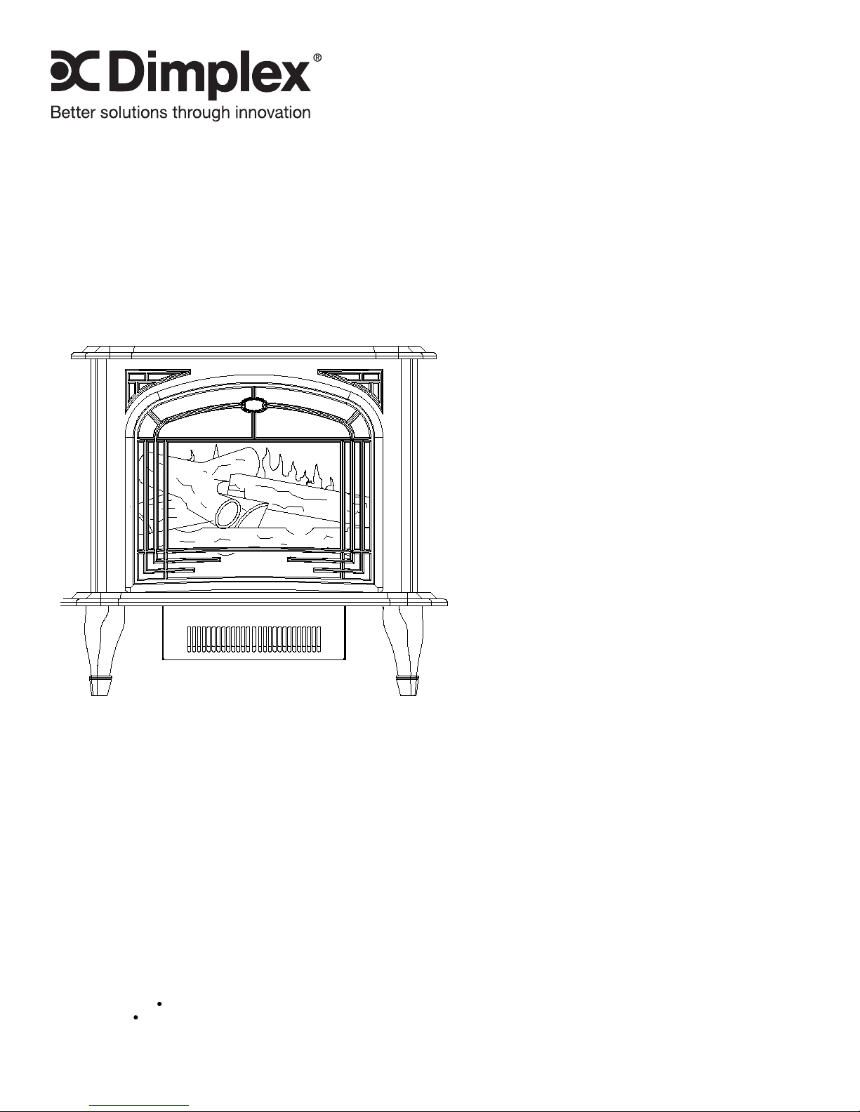
Operation
OPEN
To access the controls, go to the back of the stove.
Figure 1
A. ON/OFF SWITCH
The On/Off switch supplies power to all stove functions
(heater & ame).
B. LIGHT DIMMER CONTROL
Controls the light intensity of the log bed display area.
Rotate the knob to choose the desired setting.
C. HEATER SWITCH
The heater switch turns the heater function on and off.
D. HEATER THERMOSTAT CONTROL
To adjust the temperature to your individual requirements,
turn the thermostat control clockwise all the way to turn on
the heater. When the room reaches the desired temperature,
turn the thermostat knob counter clockwise until you hear a
click. Leave in this position to maintain the room temperature
at this setting. For additional heat, turn clockwise until you
hear the click again and the heater will turn on.
OPTIONAL REMOTE CONTROL USAGE
Plug the stove into the outlet located on the side of the 1.
receiver.
Plug the receiver into the wall outlet.2.
Install a 9 volt battery into the remote control.3.
Turn the stove’s On/Off switch to the On position prior to 4.
using the remote control.
The remote control works up to 50 feet away.5.
Push the On button to turn the stove On. Push the Off 6.
button to turn the stove off.
!
NOTE: To prevent the risk of re, the stove plug must be
inserted fully into the receiver.
!
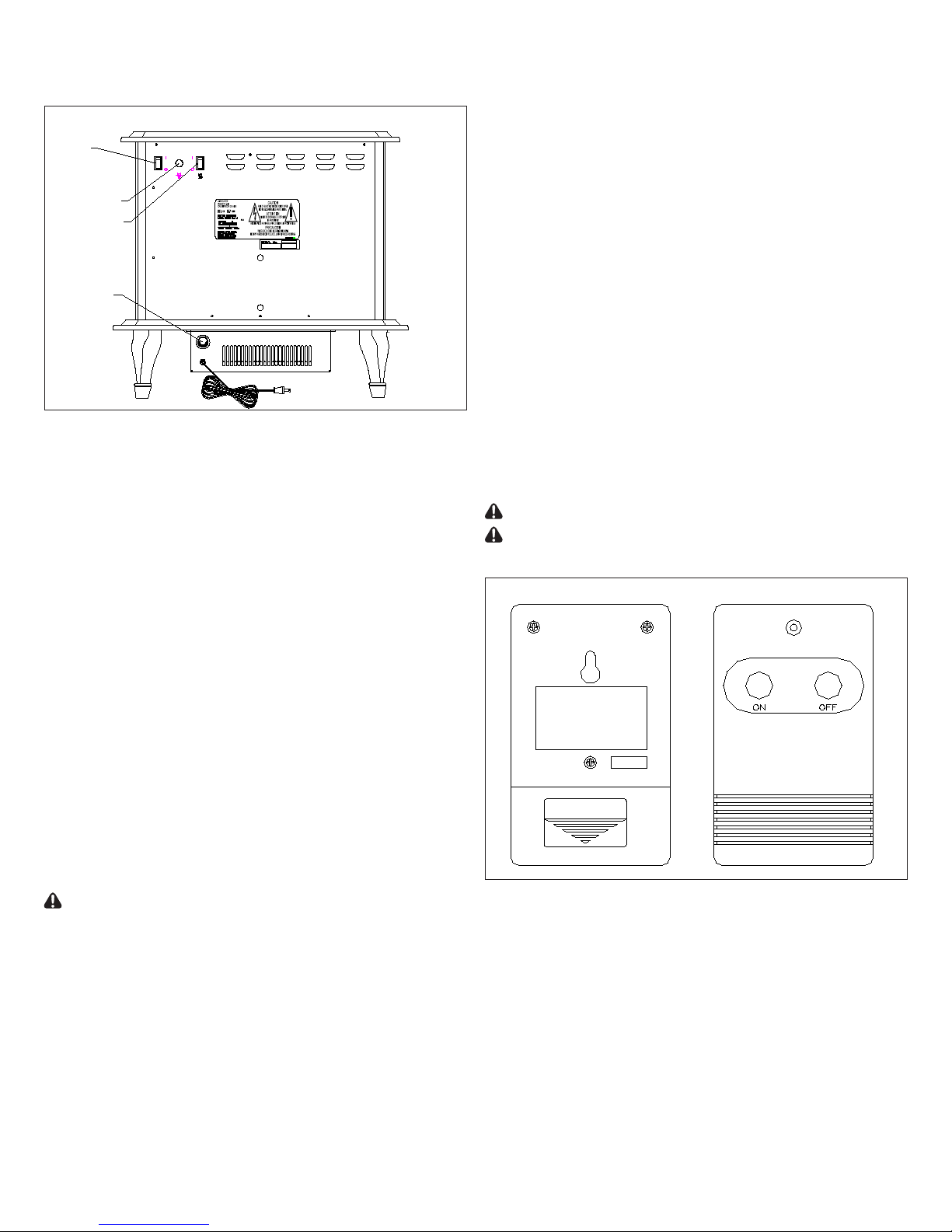
NOTE: The remote control and receiver use one of 243
independent frequencies. When replacing the remote control
or the receiver they must be replaced as a set to ensure
proper operation. The frequency of the remote is located on
the back of the remote on a label. (Figure 2)
!
NOTE: The replace On/Off switch must be in the ON
position prior to using the Remote Control.
!
NOTE: On/Off Remote Control may be used to control
most other electrical devices including T.V.’s, stereos and
lamps.
CAUTION: For indoor use in dry areas only
CAUTION: For use on 120 VAC electrical devices with
15 amp resistive load or 1/3 HP inductive load.
Figure 2
RESETTING THE TEMPERATURE CUTOFF
SWITCH
Should the heater overheat, an automatic cut out will turn the
heater off and it will not come back on without being reset.
It can be reset by switching the On/Off Switch to OFF and
waiting 5 minutes before switching the unit back on.
CAUTION: If you need to continuously reset the heater,
unplug the unit and call Dimplex North America Limited at
1-800-346-7539.
3
Maintenance
WARNING: Disconnect power before attempting any
maintenance or cleaning to reduce the risk of re, electric
shock or damage to persons.
LIGHT BULB REPLACEMENT
CAUTION: Allow at least 5 minutes for light bulbs to cool
off before touching bulbs to avoid accidental burning of skin.
Light bulbs need to be replaced when you notice a dark
section of the ame or when the clarity and detail of the log
exterior disappears. There are two bulbs under the log set
which generate the ames and embers.
Tools Required: Flat head Screwdriver
Helpful Hints: It is a good idea to replace all light bulbs at
one time if they are close to the end of their rated life. Group
replacement will reduce the number of times you need to
open the unit to replace light bulbs.
UPPER LIGHT BULB REQUIREMENTS:
MOD 0-C: 1 - 25 watt, 12 volt, 1156 Incandescent automotive
bulb. DO NOT EXCEED 25 WATTS
MOD D: 1 –15 watt candelabra E12 small base 120 volt. DO
NOT EXCEED 15 WATTS
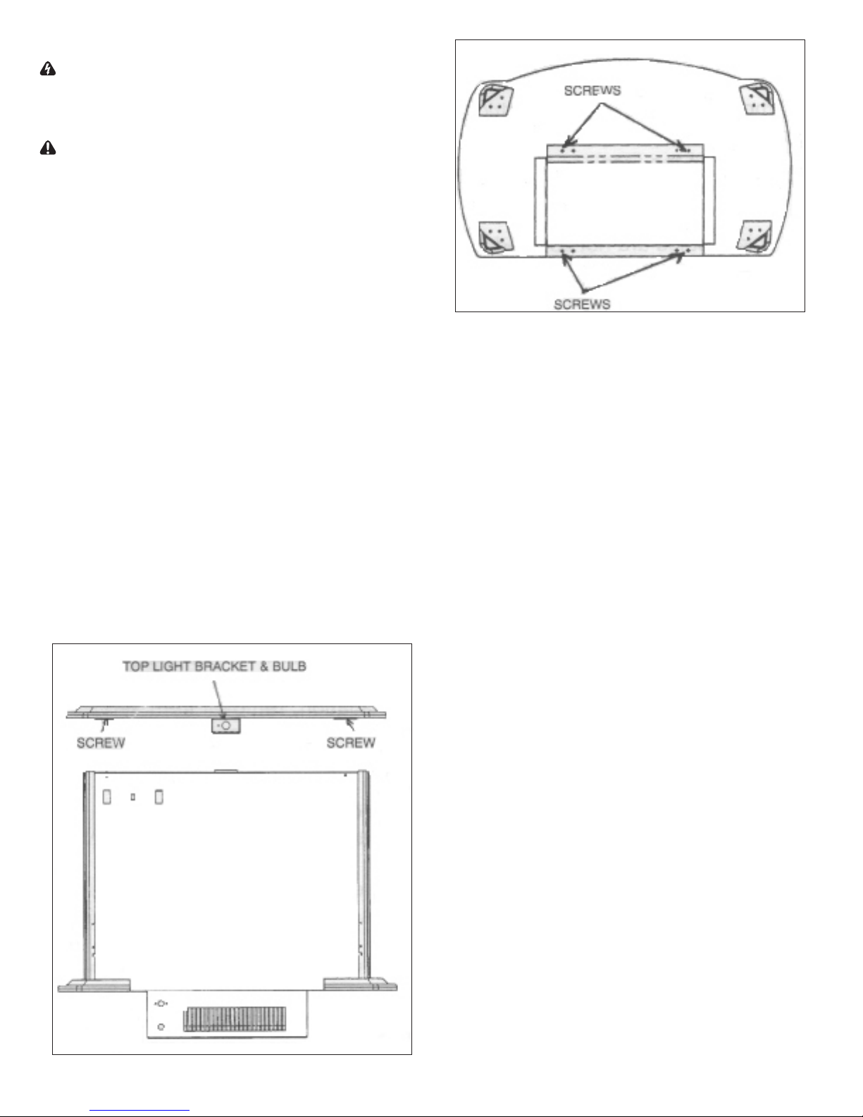
Remove the stove pipe kit (if equipped).1.
Remove the 2 screws at the upper corners of the back 2.
panel. (Figure 3) Lift the back end of the top to clear the
brackets and pull back. Lift top carefully, and place to
the side of the stove. Caution should be taken as the top
mounting brackets may scratch the nish.
Remove the burnt out bulb by pushing in and turning 3.
counter-clockwise.
Replace the upper light bulb.4.
Reassemble in the reverse order as above.5.
Figure 3
Figure 4
LOWER LIGHT BULB REQUIREMENTS:
MOD 0-A: 3 - 35 watt, 12 volt, Narrow spot Halogen bulb DO
NOT EXCEED 35 WATTS PER BULB
Remove the light cover mounting screws located on the 1.
rear cover and remove the light cover being careful not to
damage any of the wiring or light bulbs.
Remove the burnt out bulb(s) by pulling straight out of 2.
socket. If bulbs are difcult to remove from socket move
the bulb from side to side while pulling being careful not
to damage the light socket.
Replace the upper light bulb.3.
Reassemble in the reverse order as above.4.
MOD B-D: 3 – 35 watt Halogen Quartz lamps, 120 volt, G9
base. DO NOT EXCEED 35 WATTS PER BULB
Remove the stove pipe kit (if equipped).1.
Gently place stove on its back on a at surface.2.
Remove the heater cover retaining screws located on the 3.
bottom of the stove and lower heater and light assembly
out onto the oor. (Figure 4)
Remove the burnt out bulb(s) by pulling straight out of 4.
socket. If bulbs are difcult to remove from socket move
the bulb from side to side while pulling being careful not
to damage the light socket.
Replace the lower light bulbs.5.
Reassemble in the reverse order as above.6.
GLASS CLEANING
The clear door is cleaned in the factory during the assembly
operation. During shipment, installation, handling, etc., the
clear door may collect dust particles, these can be removed
by dusting lightly with a clean dry cloth.
To remove ngerprints or other marks, the clear door can
be cleaned with a damp cloth. The clear door should be
completely dried with a lint free cloth to prevent water spots.
To prevent scratching, do not use abrasive cleaners or spray
liquids on the clear door surface.
STOVE SURFACE CLEANING
Use warm water only to clean painted surfaces of the
Compact Stove. Do not use abrasive cleaners.
4
 Loading...