

Page 1

SILVERTON
SVT20
08/35674/0 Issue 3
The product complies with the European Safety Standards EN60335-2-30 and the European Standard Electromagnetic Compatibility (EMC)
EN55014, EN60555-2 and EN60555-3 These cover the essential requirements of EEC Directives 2006/95/EC and 2004/108/EC
Page 2

Table of Contents
Welcome and Congratulations ..................................................... 2
Important Instructions ................................................................... 3
Site Selection and Preparation ..................................................... 4
Log Grate Assembly ...................................................................... 6
Log Grate Installation ................................................................... 11
Operation .................................................................................... 12
Maintenance ............................................................................... 13
Additional Information ................................................................. 14
Troubleshooting .......................................................................... 15
Always use a qualifi ed technician or service agent to repair this Log grate
Note: Procedures and techniques that are considered important enough to emphasise
Caution: Procedures and techniques which, if not carefully followed, will result in damage to the
equipment
Warning: Procedures and techniques which, if not carefully followed, will expose the user to risk
of fi re, serious injury or death.
The sump and the water tank in this product are treated with a biocidal product, Silver Biocide.
This conforms with the latest relevant ISO standard
1
Page 3

Welcome and Congratulations
Thank you and congratulations for choosing to purchase a Silverton from Dimplex.
Please carefully read and save these instructions.
Caution: Read all instructions and warnings carefully before starting installation. Failure to follow
these instructions may result in a possible electric shock, fi re hazard and will void the warranty
Please record your model and seriel number below for future reference: model and serial number
can be found on the Model and Serial Number Label located on the side of the Silverton
Model Number: _________________
Serial Number: __________________
2
Page 4

Important Instructions
Please read this information guide carefully to be able to safely install, use and maintain your
product
When using electrical appliances, basic precautions should always be followed to reduce the risk
of fi re, electrical shock and injury to persons, including the following:
1. WARNING
This appliance carries a DO NOT COVER warning. Do not place material or garments on, or
obstruct the air circulation around the appliance.
2. DAMAGE
If the appliance is damaged, check with the supplier before installation and operation.
If the supply cord is damaged it must be replaced by the manufacturer or service agent or a
similarly qualifi ed person in order to avoid a hazard.
3. LOCATION
Do not use outdoors.
Do not use in the immediate surroundings of a bath, shower or swimming pool.
Do not locate the fi re immediately below a fi xed socket outlet or connection box.
Ensure that furniture, curtains or other combustible material are positioned no closer than 1 metre
from the appliance.
4. PLUG POSITIONING
The appliance must be positioned so that the plug is accessible.
Keep the supply cord away from the front of the appliance.
5. UNPLUGGING
In the event of a fault unplug the device.
Unplug the device when not required for long periods.
6. OWNER/USER
This appliance can be used by children aged form 8 years and above and persons with reduced
physical, sensory or mental capabilities or lack of experience and knowledge if they have been
given supervision or instruction concerning use of the appliance in a safe way and understand the
hazards involved. Children shall not play with the appliance. Cleaning and user maintenance shall
not be made by Children without supervision.
Children of less than 3 years should be kept away unless continuously supervised. Children aged
from 3 years and less than 8 years shall only switch on/off the appliance provided that it has been
placed or installed in its intended normal operating position and they have been given supervision
or instruction concerning use of the appliance in a safe way and understanding the hazards
involved. Children aged from 3 years and less than 8 years shall not plug in, regulate and clean
the appliance or perform user maintenance.
7. ELECTRCITY
Before switching on, please read the safety advice and operating instructions.
Note: This appliance is only to be used with the power supply unit provided.
Only plug this appliance into a supply that corresponds to that displayed on the power
supply unit. The appliance must only be supplied at extra low voltage corresponding to the
markings on the appliance
3
Page 5
CAUTION - Some parts of this product can become very hot and cause burns. Particular attention
has to be given where children and vulnerable people are present.
This instruction can be found at WWW.DIMPLEX.CO.UK
8. USAGE
Do not burn wood or other materials in the log grate
Site Selections and Preparation
This section provides instructions for selecting a location and preparing the site to install the Log
Grate
1. Select a suitable location that ensures the Log Grate is sitting on a hard level surface for
optimum fl ame effect
2. Allow for approximately 5cm of clearance behing the unit ( from the frame to the back of the
mantle) and 20cm directly above the back log to allow for removal of the Refi ll Container.
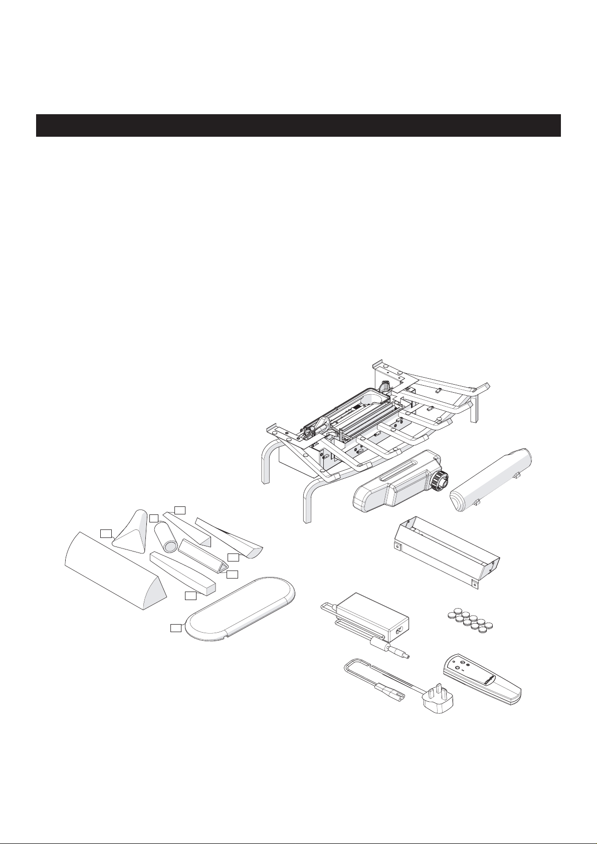
3. Carefully unpack all of the components from the box.
Caution: Handle the logs carefully, that are fragile and can easily crack or break if dropped.
5
3
1
6
4
2
7
4
Page 6
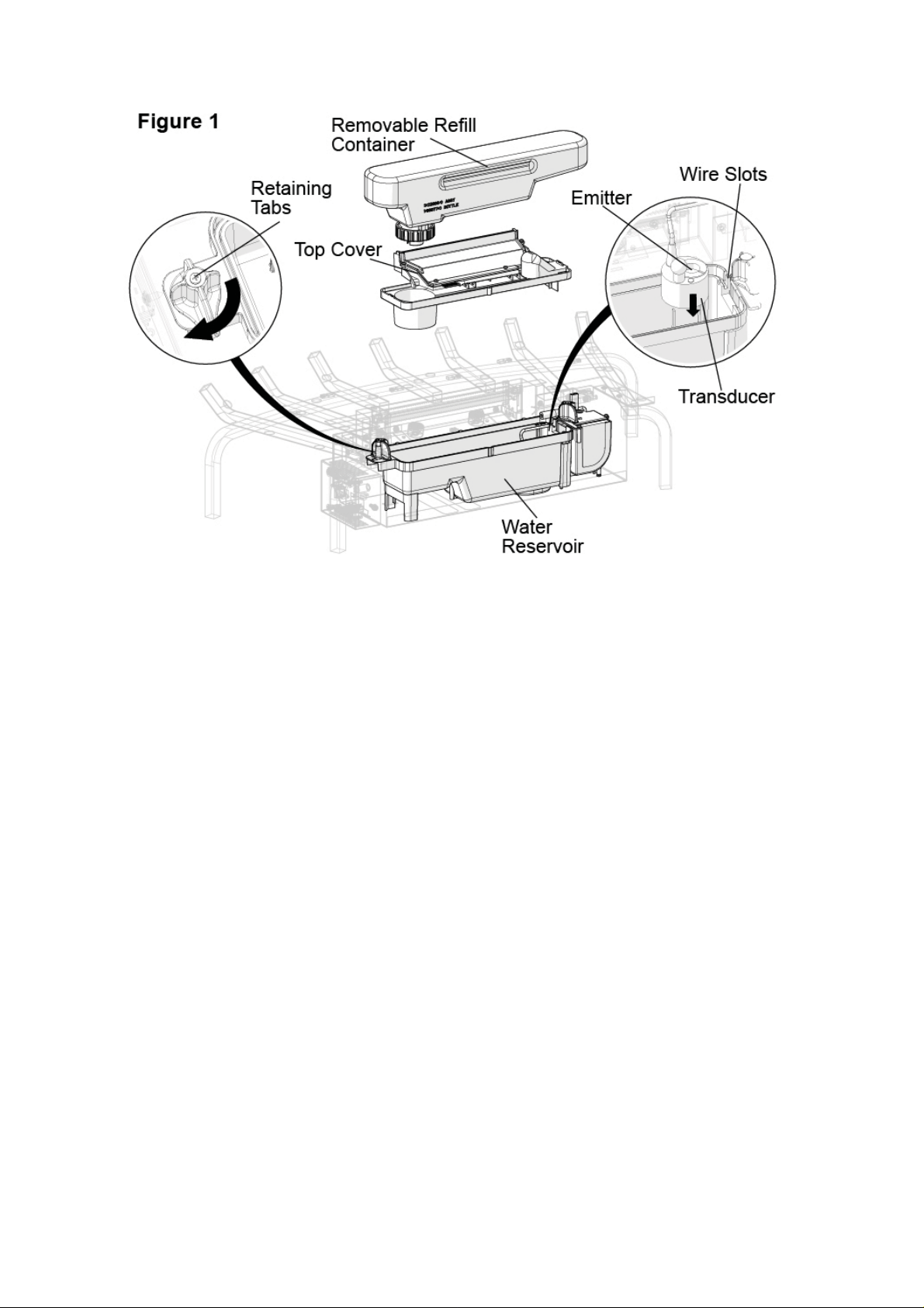
4. Unpack the transducer (contained within the water reservoir) which has been wrapped to protect
it during shipping. See Figure 1.
To access the transducer;
Remove the top cover by turning the retaining tabs on both ends of the water reservoir.•
Remove any packaging material.•
Install the transducer so that it is sitting level in the circular holding area in the resevoir.•
Orientate the transducer wire so that it does not sit directly above the Emitter and the wire •
passes through the slit in the side of the tank.
Reinstall the top cover and ensure both retaining tabs have been turned so that they are pointing •
inwards.
Note: Completely assemble the unit before fi lling the water
5
Page 7

Log Grate Assembly
Caution: Handle logs carefully, they are fragile
and can easily crack or break, if dropped.
6
Page 8

Log Grate Assembly
Each log is a separate component that needs to be placed on the grate. Position each log so that
the hook and loop pad on the backside of the log lines up with the corresponding hook and loop
pad on the log grate. These pads assist with securing the logs to the grate.
Note: Each of these logs are hand made, and as such, the hook and loop pads on the logs and
grate may not align perfectly, therefore, we have included additional pads should you need to
reposition them.
Each of the logs contain LED lights to create a fl ickering effect. During the assembly, each log
requires the electrical connectors on the log and grate to be connected as they are being placed.
In some cases, these wires can have tie wraps added to prevent the wires from being seen after
fi nal assembly. (not included)
7
Page 9

Log Grate Assembly
8
Page 10

Log Grate Assembly
9
Page 11

Log Grate Assembly
Caution: Ensure that the logs
are placed so that they are not
blocking the fl ame effect outlet
10
Page 12

Log Grate Installation
Only use fi ltered tap water in this appliance.
Once installed, never move this appliance or lay it on its back, without draining the water from the
sump and water tank.
If you intend not using the appliance for longer that 2 weeks, drain the water from the reservoir
and refi ll container.
The refi ll container, reservoir, cover and container cap must be cleaned once every two weeks,
particularly in hard water areas.
1) Fill and install the Refi ll Container.
Note: During initial installation, the Refi ll Container shouldd be refi lled after the Reservoir has fi lled
to ensure maximum operation time.
2) Make sure sure the On/Off switch is switched to Off (refer to Operating Instruction section)
3) Assemble power adapter (Figure 2). Plug the power adaptor into the front of the unit, then plug
the unit into a power socket
11
Page 13

Operation
The manual controls for the Log Grate are located on the right side (Figure 3).
A. On /Standby Switch.
Supplies power to the Log Grate
B. Momentary Button
Pressing this button toggles between Logs, Logs and fl ame effect, and Off.
Remote Control
The unit is supplied with a radio frequency remote control. This remote control has a range of
approximatly 15m. It does not have to be pointed at the fi replace and can pass through most
obstacles (including walls). It is supplied with one of 243 independent frequencies to prevent
interference with other units. The frequency designation is indicated on the back of the remote
control.
Note: Before attempting any operation with the remote control, pull the plastic insulator strip out
from between the remote casing and the battery cover (Figure 4).
Remote Control Initialisation/Reprogramming
Follow these steps for remote control initialisation and if required, re-initialisation;
Unplug the power adaptor from the unit.1.
Wait a minimum of fi ve seconds and then plug the power adapter back into the unit2.
Within ten seconds of re-acquiring power, press the ON button located on the remote 3.
control (Figure 4)
This will synchronize the remote control and the receiver
Remote Control Usage
Pressing the On button, on the remote control, switches between the two levels:
Level 1: The Logs and lights are turned on.
Level 2: The logs and lights remain on and the fl ame effect is activated.
The fi replace can be turned off at any point by pressing the OFF button on the remote control.
12
Page 14

Note: Once the mist has been activated, the unit will have to be turned Off, using either the
momentary button, on the unit, on the Off button or the remote control, then back on to return to
Level 1 - Logs and Lights only in operation.
Battery Replacement
To replace the battery,
Slide the battery cover open on the remote control (Figure 4)1.
Install one 12v (A23) battery in the battery holder2.
Close the battery cover3.
On
Button
Standby
Button
Maintenance
Warning: Disconnect the power before attempting any maintenance or cleaning to reduce the risk
of fi re, electric shock or damage to persons.
Log Grate Surface Cleaning
Use a warm damp cloth only to clean surfaces of the Log Grate. Do not use abrasive cleaners.
Water Reservoir
Note: There is no need to remove any of the logs or move the unit to access the water storage
system. However if you decide to to move the unit to perform any cleaning, ensure that the logs
are stable before cleaning.
The water storage system is located behind the back log. It can easily be removed by lifting each
of the components directly up. (Figure 5).
Note: There are tabs, on each end, that need to be turned to release the component
Caution: Only fi ltered tap water should be used in the unit to prevent scaling of the components
If you do not intend on using the unit for longer than two weeks, empty and drain the unit of water,
and dry all of the water containing components.
It is recommended that all of the water containing components are cleaned with soap and water
13
Page 15

on a biweekly basis. A small brush has been included to assist in cleaning diffi cult items/areas i.e.
the transducer
Caution: Do not put plastic components into the dishwasher.
Note: If you need to move the unit ensure that all of the components that contain water have been
emptied before relocating.
Additional Information
AFTER SALES SERVICE
Your product is guaranteed for one year from the date of purchase. Within this period, we undertake to repair or
exchange this product free of charge (excluding lamps & transducer disc and subject to availability) provided it has
been installed and operated in accordance with these instructions. Your rights under this guarantee are additional to
your statutory rights, which in turn are not affected by this guarantee.
Should you require after sales information or assistance with this product please go to www.dimplex.co.uk and select
“Customer Support” or ring our help desk on 0844 879 3589 (UK) or 01 842 4833 (R. O. I.). Spare parts are also
available on the web site. Please retain your receipt as proof of purchase.
RECYCLING
For electrical products sold within the European Community - At the end of the electrical products useful life
it not be disposed of with household waste. Please recycle where facilities exist. Check with your Local
Authority or retailer for recycling advice in your country.
14
Page 16

PATENT / PATENT APPLICATION
Products within the Optimyst range are protected by one or more of the following patents and patent applications:
Great Britain GB 2402206, GB 2460259, GB 2460453 , GB 2418014, GB 2465738, GB 2449925, GB 2465537 , GB
2455277 , GB1020534.2, GB1020537.5, GB1110987.3
United States US 7967690, US 2010299980, US 2011062250, US 2008028648, US 13/167,042
Russia RU2008140317
European EP 2029941, EP 2201301, EP 2315976, EP 1787063, EP07723217.1 , EP11170434.2, EP 11170435.9
China CN 101883953, CN 200980128666.2, CN 101057105, CN 101438104
Australia AU 2009248743, AU 2007224634
Canada CA 2725214, CA 2579444, CA 2645939
International Patent Application WO 2006027272
South Africa ZA 200808702
Mexico MX 2008011712
Korea KR 20080113235
Japan JP 2009529649
Brazil BR P10708894-9
India IN 4122/KOLNP/2008
New Zealand NZ 571900
Troubleshooting
Symptom Cause Corrective Action
The fl ame effect will
not start.
Mains plug is not plugged in.
Check plug is connected to wall socket
correctly.
The fl ame effect is too
low.
Unpleasant smell
when unit is used.
Main lamps are not
working and there are
no fl ames or smoke.
Low water level.
Low voltage connector not connected
properly. (See Fig.5)
The Transducer Unit is not sitting correctly in
the sump
The Metal Disc in the transducer might be
dirty.
The wire from the Transducer Unit is sitting
over the metal disc
Dirty or stale water.
Using unfi ltered tap water.
There is no water in the water tank Follow instructions under
Check that the water tank is full and there is
water in the sump.
Check that the connector is inserted
correctly. (See Fig.5)
Ensure the Transducer in sitting down into
the moulded recess in the sump
Clean the Metal Disc with soft brush
supplied. See ‘Maintenance.’ for a step by
step procedure.
Direct the wire to the back of the sump and
make sure it sits into the side slot exiting the
sump.
Clean the unit as described under
maintenance.
Use only fi ltered tap water.
Maintenance, ‘Filling the water tank’.
Check the plug is connected to the wall
socket correctly and that Switch ‘A’ Fig. 3 is
in the ‘ON’ ( I ) position.
15
Page 17

Page 18

Page 19

Page 20

OPTIMYST is a trade mark of GDC Group Ltd.
GDC Group Ltd.
MILLBROOK HOUSE
GRANGE DRIVE
HEDGE END
SOUTHAMPTON
TEL: 0844 879 3589
FAX: 0844 879 3583
WEBSITE: www.dimplex.co.uk
Republic of Ireland Tel. 01 8424833
SO30 2DF
c
GDC Group Ltd,
All rights reserved. Material contained in this publication may not be reproduced in whole or in part, without prior permission in
writing of Dimplex.
A division of GDC Group Ltd.
 Loading...