

Page 1
SmartRad Gebläsekonvektor SmartRad fan convector
SRX 080
SRX 120
SRX 140
SRX 180
Montage- und
Gebrauchsanweisung
Deutsch
English
Installation and
Operating instructions
Bestell-Nr. / Order no.: 8/60428/0 Iss A 01/15/B
Page 2
DE-2 SRX_de · 01/15/B www.dimplex.de
Deutsch
SRX 080, SRX 120, SRX 140, SRX 180
A
B
C
Page 3
www.dimplex.de SRX_de · 01/15/B DE-3
Deutsch
SRX 080, SRX 120, SRX 140, SRX 180
Page 4
DE-4 SRX_de · 01/15/B www.dimplex.de
Deutsch
SRX 080, SRX 120, SRX 140, SRX 180
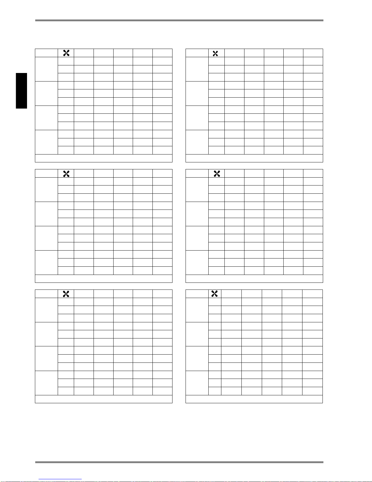
35°C 45°C 55°C 65°C 82°C
SRX180
3 1631 2734 3844 4959 6700
2 1079 1803 2530 3260 4396
1 641 1069 1499 1929 2596
SRX140
3 1299 2177 3061 3951 5342
2 838 1403 1968 2536 3421
1 493 823 1154 1484 1999
SRX120
3 1120 1878 2641 3408 4608
2 719 1201 1686 2172 2931
1 415 693 971 1249 1683
SRX080
3 759 1273 1790 2050 3125
2 479 801 1124 1448 1954
1 251 419 588 756 1018
Q = 450 l/h
35°C 45°C 55°C 65°C 82°C
SRX180
3 1059 1832 2648 3498 4796
2 820 1408 2021 2655 3601
1 558 948 1346 1750 2360
SRX140
3 900 1558 2256 2984 4078
2 671 1151 1651 2167 2932
1 442 749 1063 1378 1860
SRX120
3 806 1394 2016 2668 3637
2 591 1010 1447 1894 2564
1 379 641 907 1174 1585
SRX080
3 587 1012 1460 1926 2618
2 413 704 1005 1309 1773
1 237 399 564 728 983
Q = 150 l/h
35°C 45°C 55°C 65°C 82°C
SRX180
3 551 918 1284 1649 2214
2 487 812 1136 1460 1964
1 394 657 920 1183 1594
SRX140
3 511 852 1193 1535 2068
2 436 728 1020 1313 1773
1 338 564 791 1019 1376
SRX120
3 480 802 1124 1446 1954
2 402 672 943 1215 1642
1 302 504 707 912 1233
SRX080
3 392 655 921 1191 1620
2 312 522 734 950 1292
1 207 345 486 627 925
Q = 50 l/h
35°C 45°C 55°C 65°C 82°C
SRX180
3 1480 2502 3520 4546 5575
2 1020 1713 2406 3102 3800
1 625 1044 1464 1885 2307
SRX140
3 1199 2024 2850 3682 4438
2 802 1346 1892 2439 2935
1 484 808 1133 1459 1753
SRX120
3 1044 1760 2479 3202 3851
2 691 1160 1629 2100 2522
1 408 683 957 1231 1477
SRX080
3 719 1210 1705 2203 2663
2 465 780 1095 1412 1704
1 249 416 582 749 903
Q = 300 l/h
35°C 45°C 55°C 65°C 82°C
SRX180
3 852 1431 2020 2559 3599
2 695 1167 1647 2109 2952
1 506 848 1175 1542 2136
SRX140
3 752 1269 1798 2263 3200
2 591 995 1355 1793 2513
1 411 691 955 1251 1728
SRX120
3 689 1164 1557 2070 2930
2 530 894 1215 1606 2250
1 357 599 828 1083 1493
SRX080
3 530 902 1190 1580 2235
2 387 655 884 1163 1622
1 231 387 534 694 949
Q = 100 l/h
35/30°C 45/40°C 55/47°C 65/50°C 82/71°C
SRX180
3 1495 2856 3925 4628 7124
2 893 1760 2424 2879 4372
1 522 1008 1395 1636 2499
SRX140
3 1078 2172 2982 3492 5446
2 631 1329 1828 2154 3314
1 344 752 1039 1176 1898
SRX120
3 870 1826 2506 2924 4594
2 561 1119 1541 1770 2784
1 331 621 856 1017 1586
SRX080
3 573 1165 1595 1777 2962
2 358 695 956 1137 1809
1 201 375 516 607 941
Page 5

www.dimplex.de SRX_de · 01/15/B DE-5
Deutsch
SRX 080, SRX 120, SRX 140, SRX 180
1078
217 2
2982
3492
5446
631
132 9
1828
2154
3314
344
752
1039
1176
1898
870
182 6
2506
2924
4594
561
111 9
1541
1771
2784
331
621
856
1017
1586
0
1000
2000
3000
4000
5000
6000
35/30°C 47/40 °C 55/47 °C 65/50°C 8 2/71°C
Vorlauftem peratur / Flow t emperatue
Ausgangsleistung SRX 120 und SRX 140
Output Power SRX 120 and SRX 140
SRX140- Stufe 3
SRX140- Stufe 2
SRX140- Stufe 1
SRX120- Stufe 3
SRX120- Stufe 2
SRX120- Stufe 1
149 5
285 6
392 5
462 8
712 4
893
176 0
242 4
287 9
437 2
522
100 8
139 5
163 6
249 9
573
116 5
159 5
177 7
296 2
358
695
956 113 7
180 9
201
375
516
607
941
0
100 0
200 0
300 0
400 0
500 0
600 0
700 0
35/3 0°C 47/40 °C 55/47 °C 65/5 0°C 82/7 1°C
Vorlauftemperatur
Flow temperatue
Ausgangsleistung SRX 180 und SRX 080
Output Power SRX 180 and SRX 080
SRX 180 - Stufe 3
SRX 180 -Stufe 2
SRX 180 - Stufe 1
SRX0 80- Stufe 3
SRX0 80- Stufe 2
SRX0 80- Stufe1
Page 6
DE-6 SRX_ba · 01/15/B www.dimplex.de
Deutsch
SRX 080, SRX 120, SRX 140, SRX 180
English
Inhaltsverzeichnis, Table of contents
Grafiken, Graphics DE-2
Inhaltsverzeichnis DE-6
Garantie, Kundendienst, Anschrift DE-7
1 Sicherheitshinweise DE-8
2 Gerätebeschreibung DE-8
3 Montagevorbereitung DE-9
4 Befestigung an der Wand DE-9
5 Hydraulischer Anschluss DE-9
6 Elektrischer Anschluss DE-9
6.1 Aderbelegung der Anschlussleitung DE-9
6.2 Temperaturabsenkung über externe Schaltuhr oder Schalter DE-9
6.3 Betrieb mit Programmkassette DE-10
7 Anschluss von externen Zusatzgeräten DE-10
7.1 Anschluss einer Umwälzpumpe oder Ventils DE-10
7.2 Anschluss eines motorbetriebenen Ventils DE-10
8 Einstellung der Software-Eigenschaften DE-10
8.1 Schlafzimmer-Funktion DE-10
8.2 Hoch-Temperatur Funktion DE-10
8.3 Absenkbetrieb DE-11
8.4 Betriebsart DE-11
8.5 Relais Funktion DE-11
8.6 Tastensperre DE-11
9 Fertigmontage DE-11
10 Bedienung DE-11
11 Manueller Betrieb DE-11
12 Automatischer Betrieb (eco) DE-11
13 Inbetriebnahme mit Luft/Wasser Wärmepumpen DE-11
14 Störungsanzeige DE-11
15 Fehlerdiagnose DE-12
16 Frostschutz DE-13
17 Außenflächen reinigen DE-13
18 Wartung DE-13
19 Garantie DE-13
20 Entsorgungshinweis DE-13
21 Technische Geräteinformationen DE-13
1 Safety Information EN-14
2 Device description EN-14
3 Installation preparation EN-15
4 Fixing to the wall EN-15
5 Hydraulic connection EN-15
6 Electrical connection EN-15
6.1 Conductor configuration of the connection cable EN-15
6.2 Lowering temperature an external timer or switch EN-15
6.3 Operation with programming cassette EN-15
7 Connection to external devices EN-16
7.1 Connection to pump or valve EN-16
7.2 Connection to motor valve EN-16
8 SmartRad Software feature EN-16
8.1 Bedroom mode EN-16
8.2 High temperature mode EN-16
8.3 Setback mode EN-16
8.4 Operation Mode EN-16
8.5 Relais mode EN-16
8.6 Keylock operation EN-16
9 Final installation EN-16
10 Operation EN-17
11 Manual operation EN-17
12 Automatic mode (eco) EN-17
13 Operation with air/water heat pumps EN-17
14 Fault indication EN-17
15 Frost protection EN-17
16 Cleaning outer surfaces EN-17
17 Maintenance - to be performed by a specialist EN-17
18 Warranty EN-17
19 Disposal EN-17
20 Technical device information EN-18
21 Fault diagnosic EN-19
Page 7

www.dimplex.de SRX_de_ba · 01/15/B DE-7
Deutsch
SRX 080, SRX 120, SRX 140, SRX 180
Garantie, Kundendienst, Anschrift
Garantieurkunde
Kundendienst
Im Kundendienstfall ist Glen Dimplex Deutschland GmbH als zuständiger Kundendienst zu informieren.
Glen Dimplex Deutschland GmbH
Telefon: +49 (0) 9221 709-564
Telefax: +49 (0) 9221 709-589
E-Mail: 09221709589@dimplex.de
Für die Auftragsbearbeitung werden die Erzeugnisnummer (E-Nr.) und das Fertigungsdatum (FD) des Gerätes benötigt. Diese Angaben
befinden sich auf dem Typenschild, in dem stark umrandeten Feld.
Glen Dimplex Deutschland GmbH Telefon: +49 (0) 9221 709-564
Am Goldenen Feld 18 Telefax: +49 (0) 9221 709-589
D-95326 Kulmbach E-Mail: 09221709589@dimplex.de
Technische Änderungen vorbehalten www.dimplex.de
gültig für Deutschland und Österreich
Die nachstehenden Bedingungen, die Voraussetzungen und Umfang
unserer Garantieleistung umschreiben, lassen die Gewährleistungsverpflichtungen des Verkäufers aus dem Kaufvertrag mit dem Endabnehmer unberührt. Für die Geräte leisten wir Garantie gemäß
nachstehender Bedingungen:
Wir beheben unentgeldlich nach Maßgabe der folgenden Bedingungen Mängel am Gerät, die nachweislich auf einen Material- und/oder
Herstellungsfahler beruhen, wenn sie uns unverzüglich nach Feststellung und innerhalb von 24 Monaten nach Lieferung an den Erstabnehmer gemeldet werden. Bei gewerblichen Gebrauch innerhalb von 12
Monaten. Zeigt sich der Mangel innerhalb von 6 Monaten ab Lieferung, wird vermutet, dass es sich um einen Material- oder Herstellungsfahler handelt.
Dieses Gerät fällt nur dann unter diese Garantie, wenn es von einem
Unternehmer in einem der Mitgliedsstaaten der Europäischen Union
gekauft wurde, es bei Auftreten des Mangels in Deutschland oder
Österreich betrieben wird und Garantieleistungen auch in Deutschland
oder Österreich erbracht werden können.
Die Behebung der von uns als garantiepflichtig anerkannter Mängel
geschied dadurch, dass die mangelhaften Teile unentgeldlich nach
unserer Wahl instantgesetzt oder durch einwandfreie Teile ersetzt
werden. Durch Art oder Ort des Einsatzes des Gerätes bedingte außergewöhnliche Kosten der Mängelbeseitigung werden nicht übernommen. Der freie Gerätezugang muss durch den Endabnehmer
gestellt werden. Ausgebaute Teile, die wir zurücknehmen, gehen in
unser Eigentum über. Die Garantie erstreckt sich nicht auf leicht zerbrechliche Teile, die den Wert oder die Gebrauchstauglichkeit des Gerätes nur unwesentlich beeinträchtigten.
Es ist jeweils der Originalkaufbeleg mit Kauf- und/oder Lieferdatum
vorzulegen.
Die Garantiezeit für Nachbesserungen und Ersatzteile endet mit dem
Ablauf der ursprünglichen Garantiezeit für das Gerät.
Zur Erlangung der Garantie für Fußbodenheizmatten ist dass in den
Projektierungsunterlagen oder in der Montageanweisung enthaltenen
Prüfprotokoll ausgefüllt innerhalb vier Wochen nach Einbau der Heizung an untenstehende Adresse zu senden.
Eine Garantieleistung entfällt, wenn vom Endabnehmer oder einem
Dritten die entsprechenden VDE-Vorschriften, die Bestimmungen der
örtlichen Versorgungsunternehmen oder unsere Montage- und Gebrauchsanweisung nicht beachtet worden sind. Durch etwa seitens
des Endabnehmers oder Dritter unsachgemäß vorgenommenen Änderungen und Arbeiten wird die Haftung für die daraus entstehenden
Folgen aufgehoben. Die Garantie erstreckt sich auf vom Lieferer bezogenen Teile. Nicht vom Lieferer bezogene Teile und Gerät-, bzw. Anlagenmängel, die auf nicht vom Lieferer bezogene Teile zurück zuführen sind fallen nicht unter den Garantieanspruch.
Sofern ein Mangel nicht beseitigt werden kann oder die Nachbesserung von uns abgelehnt oder unzumutbar verzögert wird, wird der Hersteller entweder kostenfreien Ersatz liefern oder den Minderwert
vergüten. Im Falle einer Ersatzlieferung behalten wir uns die Geltendmachung einer angemessenen Nutzungsanrechnung für die bisherigen Nutzungszeit vor. Weitergehende oder andere Ansprüche,
insbesondere solche auf Ersatz außerhalb des Gerätes entstandener
Schäden, sind soweit eine Haftung nicht zwingend gesetzlich angeordnet ist, ausgeschlossen.
Bei einer Haftung nach § 478 BGB wird die Haftung der Liefereres auf
die Servicepauschalen des Lieferers als Höchstbetrag beschränkt.
Page 8

DE-8 SRX_de · 01/15/B www.dimplex.de
Deutsch
SRX 080, SRX 120, SRX 140, SRX 180
1. Sicherheitshinweise
HINWEIS
Sehr geehrter Kunde,
Das Gerät darf nur, wie in der Montage- und Gebrauchsanleitung beschrieben, verwendet werden!
Bitte lesen Sie alle in dieser Anweisung aufgeführten
Informationen aufmerksam durch. Bewahren Sie die
Anweisung sorgfältig auf und geben Sie diese gegebenenfalls an Nachbesitzer weiter.
ACHTUNG!
Diese Gerät kann von Kindern ab 8 Jahren
und darüber sowie von Personen mit
verringerten physischen, sensorischen oder
mentalen Fähigkeiten oder Mangels an
Erfahrung und Wissen benutzt werden, wenn
sie beaufsichtigt oder bezüglich des sicheren
Gebrauchs des Gerätes unterwiesen wurden
und die daraus resultierenden Gefahren
verstehen! Kinder dürfen nicht mit dem Gerät
spielen. Reinigung und Benutzerwartung
dürfen nicht durch Kinder ohne Aufsicht
erfolgen!
ACHTUNG!
Kinder jünger als 3 Jahre sind fernzuhalten,
es sei denn, sie werden ständig überwacht.
Kinder ab 3 Jahren und jünger als 8 Jahre
dürfen das Gerät ein- und ausschalten, wenn
sie beaufsichtigt werden oder bezüglich des
sicheren Gebrauchs des Gerätes unterwiesen wurden und die daraus resultierenden
Gefahren verstanden haben, vorausgesetzt,
dass das Gerät in seiner normalen Gebrauchslage platziert oder installiert ist!
ACHTUNG!
Kinder ab 3 Jahren und jünger als 8 Jahre
dürfen nicht den Stecker in die Steckdose
stecken, das Gerät nicht regulieren, das
Gerät nicht reinigen und/oder nicht die
Wartung durch den Benutzer durchführen!
ACHTUNG!
Einige Teile des Gerätes können sehr heiß
werden und Verbrennungen verursachen.
Besondere Vorsicht ist geboten, wenn Kinder
oder schutzbedürftige Personen anwesend
sind!
ACHTUNG!
Das Gerät darf nicht unter einer Wandsteckdose aufgestellt werden!
ACHTUNG!
Wenn das Netzkabel beschädigt ist, muss es
vom Hersteller oder dessen Kundendienstvertretung oder einer vergleichbar qualifizierten Person ausgetauscht werden, um
Gefahrenquellen auszuschalten!
ACHTUNG!
Um Überhitzungen zu vermeiden, darf das
Heizgerät nicht abgedeckt werden!
ACHTUNG!
Das nebenstehende Symbol ist am
Heizgerät angebracht und bedeutet,
dass das Heizgerät nicht abgedeckt
werden darf!!
ACHTUNG!
Das Gerät muss so installiert werden, dass
die Bedienelemente nicht von einer Person,
die sich in der Badewanne oder unter einer
Dusche befindet, berührt werden können.
Gerät nur an Wechselspannung-Spannung gemäß
Typenschild anschließen.
Das Gerät ist nach den geltenden Sicherheitsvor-
schriften von einer Fachkraft zu installieren.
Das Gerät darf nur zur Raumlufterwärmung inner-
halb geschlossener Räume verwendet werden.
Reparaturen und Eingriffe in das Gerät dürfen nur
von einem Fachmann ausgeführt werden.
Im Fehlerfall oder bei längerer Außerbetriebnahme
Gerät vom Netz trennen (Sicherung ausschalten).
In Räumen, in denen feuergefährliche Stoffe ver-
wendet werden (z.B. Lösungsmittel etc.), darf das
Heizgerät nicht betrieben werden.
2. Gerätebeschreibung
Beim Modell SmartRad handelt es sich um einen Gebläsekonvektor zur Erwärmung von Wohnräumen. Der
Gebläsekonvektor ist zum Anschluss an eine zentrale
Heizungsanlage vorgesehen. Der Gebläsekonvektor
ist für den Einsatz in Wärmepumpen-Anlagen geeignet, kann aber ebenso in Verbindung mit anderen Heizungsanlagen, z.B. mit Öl- und Gasfeuerungen betrieben werden. Das Gerät saugt auf der Geräteunterseite
Luft an. Diese wird im Wärmetauscher erwärmt und
nach oben ausgeblasen.
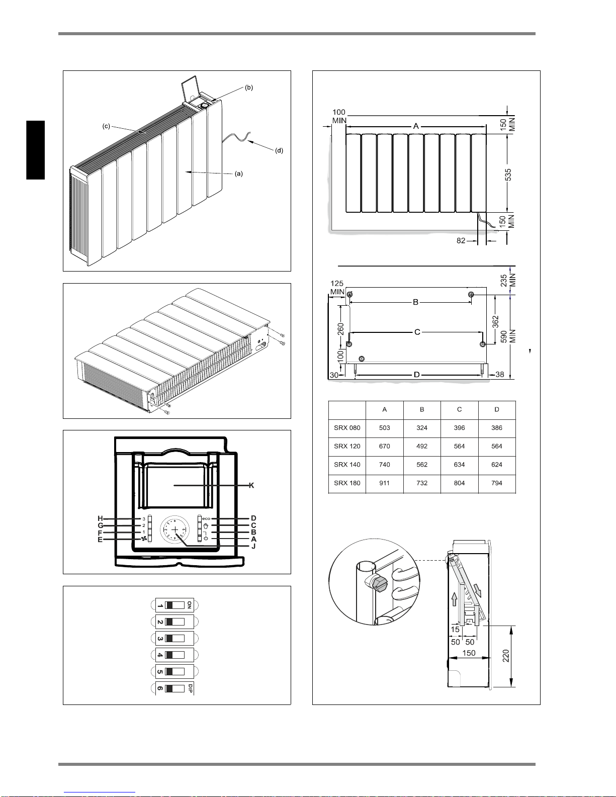
Abb.1
(a) Gehäuseabdeckung
(b) Bedienfeld
(c) Luftaustrittsgitter
(d) Anschlussleitung 1m
Die Gebläsekonvektoren dürfen nur in Zentralhei-
Page 9

www.dimplex.de SRX_de · 01/15/B DE-9
Deutsch
SRX 080, SRX 120, SRX 140, SRX 180
zungsanlagen mit geschlossenem Regelkreis verwendet werden.
Die Heizungsanlage muss als Zweirohrsystem ausgeführt sein.
Die Geräte müssen ausreichend dimensioniert werden,
um die Wärmeverluste im Raum ausgleichen zu können.
3. Montagevorbereitung
Verpackungsmaterial entfernen. Der Karton bzw. der
Kunststoffverpackung kann zur Abdeckung des Gerätes bei den Installation- oder Renovierungssarbeiten
verwendet werden, um Verschmutzungen durch Putz
oder Farbe zu vermeiden.
Die vier Befestigungsschrauben an der Geräteunterseite abschrauben (siehe Abb.2), um die Gehäuseabdekkung abnehmen zu können. Die Gehäuseabdeckung
so aufbewahren, dass Beschädigungen während der
Installationsarbeiten ausgeschlossen werden.
4. Befestigung an der Wand
Bei Trockenbauwänden, geeignetes Befestigungsmaterial verwenden (nicht im Lieferumfang enthalten)!
Wie in Abb. 5 (b) gezeigt, an einer stabilen Wand vier
Bohrlöcher anzeichnen und bohren. Alle Maße in mm.
Dübel einsetzen und die beiden oberen Schrauben
vormontieren (noch nicht vollständig eindrehen).
Das Gerät in die beiden oberen Schrauben einhängen.
Die beiden unteren Schrauben einsetzen und festdre-
hen, anschließend die beiden oberen Schrauben ebenfalls festdrehen.
5. Hydraulischer Anschluss
Um einen ausreichenden Heizwasserdurchfluss durch
die Gebläsekonvektoren sicherzustellen, sind folgende
Punkte zu beachten:
Die Geräte sind für die Installation an Einrohrsyste-
men nicht geeignet.
Die Anschlussrohr-Nennweite muss einen Min-
dest-Durchmesser von 15 mm aufweisen.
Werden die Geräte an einer Heizungsanlage mit
verschiedenen Wärmeverteilsystemen (z.B. Fußbodenheizung) installiert, ist ein separater Kreislauf
vorzusehen, um einen ausreichenden Wasserdurchfluss zu gewährleisten.
Für einen optimalen Betrieb (Wärmeabgabe) der
Gebläsekonvektoren ist ein hydraulischer Abgleich
an der Heizungsanlage erforderlich.
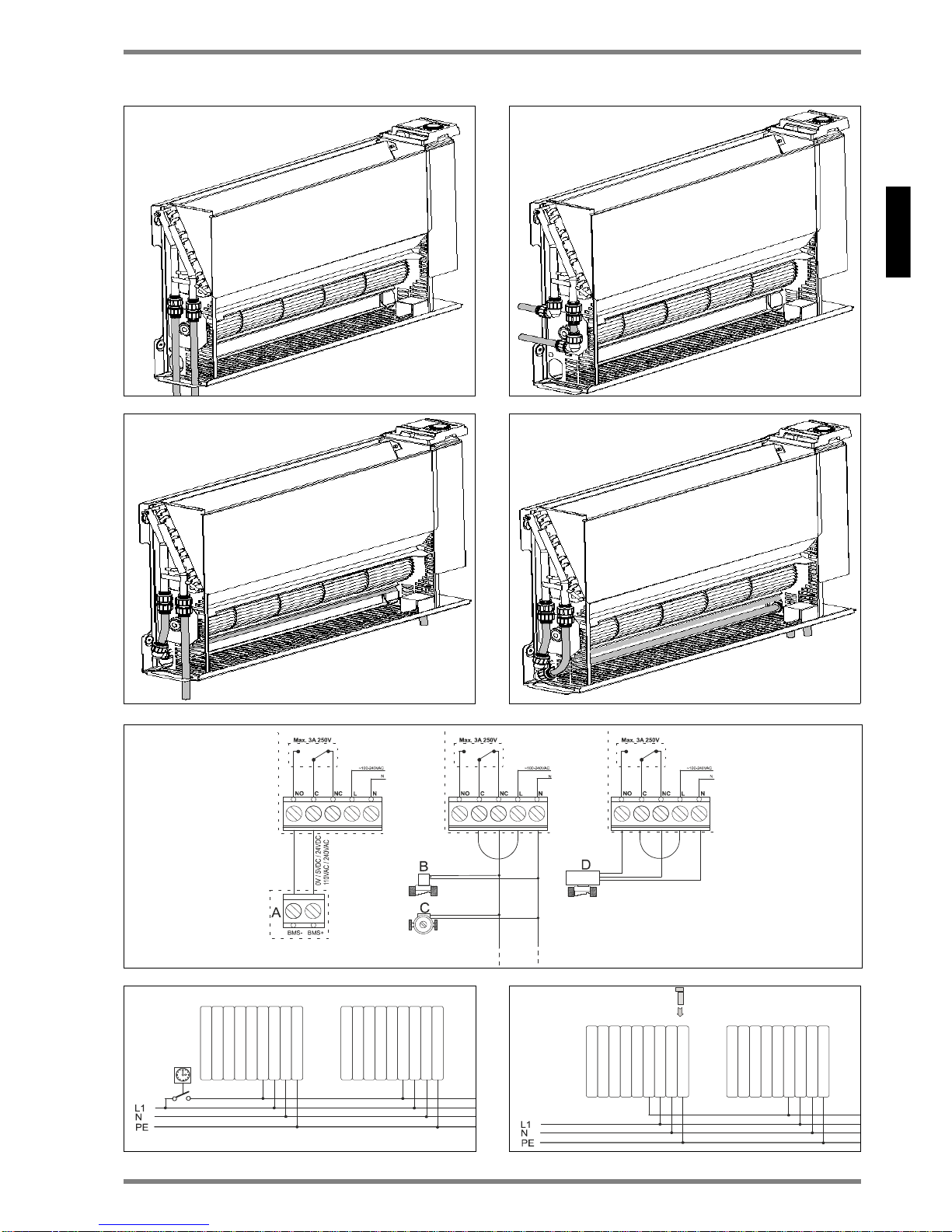
Abb. 6 zeigt die verschiedenen hydraulischen Anschlussmöglichkeiten am Gerät. Die empfohlenen Vorund Rücklaufanschlüsse sind in Abb. 6 dargestellt. Die
Verlegung der Heizungsrohre zum Gerät kann im
Boden oder in der Wand erfolgen.
Als Sonderzubehör ist ein Anschlussset VS SRX mit
Vor- und Rücklaufleitung und ein Hahnblock mit Stellantrieb ETS DWU erhältlich.
Das Gerät wird werkseitig mit zwei am Wärmetauscher
montierten Kupferrohrleitungen, Durchmesser 15 mm,
geliefert.
Vor und während des Befüllens der Heizungsanlage
müssen alle Rohrverbindungen auf Dichtheit überprüft
werden. Während der Befüllung muss das Entlüftungsventil (siehe Abb. 5 (c)) geöffnet sein, damit die Luft im
Gerät entweichen kann. Nach der Inbetriebnahme
(Umwälzpumpe läuft) gegebenenfalls erneut entlüften.
6. Elektrischer Anschluss
ACHTUNG!
Das Gerät muss geerdet werden!
ACHTUNG!
Phasenleiter (braun) und Nullleiter (blau) dürfen nicht
vertauscht werden, da dies zu Funktionsstörungen
führen kann!
Der elektrische Anschluss ist an einer Versorgungsspannung ~100 - 230V, 50/60 Hz vorzunehmen.
Vor Ausführen der Installationsarbeiten sicherstellen,
dass die Spannungsversorgung abgeschaltet ist.
Das Gerät ist mit einer flexiblen Anschlussleitung von
1 m Länge (4 x 0,75 mm²) ausgestattet, mit der das
Heizgerät direkt über eine geeignete Wandanschlussdose an die elektrische Versorgung angeschlossen
werden kann.
In der elektrischen Zuleitung ist ein Trennschalter für
jeden Pol mit einer Kontaktöffnungsweite von mindestens 3 mm vorzusehen. Als Trennvorrichtung sind auch
Sicherungsautomaten zulässig. Die Sicherungsautomaten sollten eine träge Auslösecharakteristik haben.
6.1 Aderbelegung der Anschlussleitung:
Braun: ,L‘ – Phasenleiter Versorgungsspannung
Blau: ‚N‘ – Nullleiter Versorgungsspannung
Grün/Gelb: ‚PE‘ - Schutzleiter
Schwarz: Steuerleiter (Absenkung; Ein/Aus)
Schaltbild siehe Abb. 8.
Steuerleiter
ACHTUNG!
Bei Betrieb mehrerer SmartRad Konvektoren über
einen Steuerleiter ist phasengleicher Anschluss
sicherzustellen!
Der schwarze Steuerleiter hat folgende Funktionen:
6.2 Temperaturabsenkung über externe Schaltuhr
oder Schalter
Durch Ansteuern des Steuerleiters, siehe Abb. 8 links,
wird die am Gerät eingestellte Solltemperatur abgesenkt.
Die Temperaturabsenkung wird über den Steuerleiter
an eventuell nachgeschaltete Geräte weitergegeben.
Page 10

DE-10 SRX_de · 01/15/B www.dimplex.de
Deutsch
SRX 080, SRX 120, SRX 140, SRX 180
6.3
Betrieb mit Programmierkassette
Die Steuersignale der im Pilotgerät eingesteckten Programmierkassette werden über den Steuerleiter an
eventuell nachgeschaltete Geräte weitergegeben,
siehe Abb. 9.
Bei Betrieb mit den Programmierkassette bitte die
Funktionen in obenstehender Tabelle beachten.
Wird der Steuerleiter nicht verwendet, muss dieser
fachgerecht isoliert werden.
ACHTUNG!
Beim Umschalten auf gesteuerten Betrieb liegt an
dieser Leitung Netzspannung an!
ACHTUNG!
Steuerleiter nicht erden!
Bei Außerbetriebnahme, z.B. für Wartungsarbeiten, ist
sicherzustellen, dass neben der Netzversorgung auch
der Steuerleiter spannungsfrei geschaltet ist, da dieser
eventuell Fremdspannung führen kann (über einen
Schaltuhrkontakt oder Pilotgerät mit Programmierkassette).
7. Anschluss von externen Zusatzgeräte
An den EC SmartRad Gebläsekonvektor können weitere externe Zusatzgeräte für energieeffiziente Nutzung angeschlossen werden. Dies wird ermöglicht
durch ein Schaltrelais auf der internen Steuerplatine
Abb 7).
Beim Anschluss an ein Home Management System
kann das Relais als potentialfreien Kontakt genutzt
werden. Dies kann genutzt werden zur Übertragung an
ein geeigneten Steuersystem „A“ (Abb.7a).
Beim Anschluss von Umwälzpumpen oder Steuerventilen werden diese durch den SmartRad mit Spannung
versorgt.
7.1 Anschluss einer Umwälzpumpe oder Ventil
Ein Standart Magnetventil oder ein selbsttätig rückstellendes Ventil (B) der eine Standart-Umwälzpumpe „C“
werden wie in Abb.7b) angeschlossen.
NO = normal geöffnet - die Pumpe/ Ventil arbeitet.
N = Nullleiter für Pumpe/ Ventil
ACHTUNG!
Die Umwälzpumpe / Stellantrieb müssen der
Nennspannung des SmartRad entsprechen!
ACHTUNG!
Die maximale Strombelastung der Relaiskontakte
beträgt 3A bei 250V~!
7.2 Anschluss eines motorbetriebenen Ventils
Der SmartRad kann ein Standart-Ventil schalten und
dies über die Leiterplatte mit Spannung versorgen.
NO= normal geöffnet - das Ventil wird geöffnet
NC= normal geschlossen - das Ventil wird geschlossen
N = Nullleiter für Ventil.
Beachten Sie die Eigenschaften des von Ihnen verwendeten Stellantriebes für das Ventil (stromlos geöffnet
oder geschlossen).
Abb.7 b zeigt Anschluss eines Stellantrieb für „stromlos
geöffnet“. Bei Version „stromlos geschlossen“ muss
der Kontakt NO belegt werden.
8. Einstellung des Software- Eigenschaften
Der SmartRad Konvektor besitzt eine Anzahl von Software-Einstellungen mit der Hilfe die Benutzerfreundlichkeit und Komfort bei der Nutzung verbessert werden können.
Die verschiedenen Einstellungen werden mittels eines
DIP Schalters auf der Leiterplatte vorgenommen. Die
Auswahl und Einstellung der Zusatzfunktion geschieht
zweckmäßigerweise bei der Installation des Gerätes.
8.1 Schlafzimmer-Funktion
Leiser Betrieb durch eine Reduzierung des Lüfterdrehzahl. Diese Funktion eignet sich für Räume mit sehr
niedriger Geräuschkulisse, wie z.B Schlafzimmer.
Dazu verstellen Sie den Schalter Nr.1 am DIP Schalter.
HINWEIS
Diese Betriebsart reduziert die Leistung des SmartRad
und daher sollte das Gerät für die Raumgröße
ausreichend dimensioniert sein.
8.2 Hoch-Temperatur Funktion
Diese Betriebsart ist für die Nutzung an einem Hochtempertur-Heizkreis, wie z.B. Öl- oder Gasheizungsanlagen.
In diesem Modus wird die untere Wassertemperaturgrenze auf 45 ° C erhöht.
Dazu verstellen Sie den Schalter Nr.2 am DIP Schalter.
Programm-
kassette
Abschalt-
betrieb
Absenk
betrieb
RXPW 1
7 Tage Timer
Ja Nein
RXTI 24
24 Stunden Timer
Ja Nein
Page 11

www.dimplex.de SRX_de · 01/15/B DE-11
Deutsch
SRX 080, SRX 120, SRX 140, SRX 180
8.3 Absenkbetrieb
Bei Verwendung mit Steuerleitung:
In diesem Modus, wenn ein Absenksignal (Sollwert zu
reduzieren) empfangen wird. Dabei wird der Sollwert
gleitend reduzieren, um eine bestimmte Wärmemenge
im Raum zu halten. Wenn diese Betriebsart ausgeschaltet ist, wird der Absenkbetrieb in die Betriebsart
„Frostschutz“ zurück gesetzt.
Der normale Komfort Betrieb ist nicht von dieser Einstellung betroffen.
8.4 Betriebsart
Bei diesem Gerätetyp ist nur „Heizbetrieb“ verfügbar.
Der DIP-Schalter 4 sollte immer ausgeschaltet sein.
8.5 Relais Funktion
Bei dieser Funktion wird das Relais entsprechend der
Betriebsbedingungen aktiviert.
Dazu verstellen Sie den Schalter Nr.6 am DIP Schalter.
8.6 Tastensperre-Modus
Dieser Modus sollte für den öffentlichen Bereichen wie
Schulen oder Büros genutzt werden und deaktiviert die
Bedienelemente am Gerät.
Zum Aktivieren drücken Sie die Taste länger als 15
Sekunden.
Dies deaktivieren die und Taste sowie den
Thermostatknopf.
Zum Deaktivieren der Tastensperre drücken Sie die
dieTaste länger als 15 Sekunden.
9. Fertigmontage
Nach Abschluss der Installationsarbeiten die Gehäuseabdeckung aufsetzen. Dazu die vier Befestigungsschrauben an der Geräteunterseite einschrauben,
siehe Abb. 2.
10. Bedienung
Das Bedienfeld ist in Abb. 3 dargestellt.
Die einzelnen Elemente haben folgende Bedeutung:
A - Taste Betriebsart
B - Anzeige EIN/AUS
C - Anzeige Manueller Betrieb
D - Anzeige Automatischer Betrieb
F - Taste Lüfterstufe
F - Anzeige kleine Lüfterstufe
G - Anzeige mittlere Lüfterstufe
H - Anzeige große Lüfterstufe
J - Einstellrag Thermostat
K - Abdeckung für Steckplatz Programmierkassette
11. Manueller Betrieb
Taste einmal oder mehrmals drücken bis die gelbe
Anzeige aufleuchtet.
Taste einmal oder mehrmals drücken um die ge-
wünschte Lüfterstufe (Lüfterdrehzahl) zu wählen. Die
eingestellte Lüfterstufe wird über die rote Anzeige (1,2,
3) signalisiert. Mit dem Drehknopf die gewünschte
Raumtemperatur einstellen. Die eingestellte Lüfterstufe wird in Abhängigkeit der Raumtemperatur ein- bzw.
ausgeschaltet. Die Temperaturabsenkung wird über
den Steuerleiter an eventuell nachgeschaltete Geräte
weitergegeben.
12. Automatischer Betrieb (eco)
Taste einmal oder mehrmals drücken bis die rote
Anzeige eco aufleuchtet.
Mit dem Drehknopf die gewünschte Raumtemperatur
einstellen. In Abhängigkeit der aktuellen Raumtemperatur und der am Thermostaten eingestellten Solltemperatur ermittelt die Elektronik eine der drei möglichen
Lüfterstufen (Lüfterdrehzahl). Je nach Differenz zwischen aktueller Raum- und gewünschter Solltemperatur wählt die Elektronik die erforderliche Lüfterstufe.
Bei Bedarf kann die Anzahl der möglichen Lüfterstufen
reduziert werden. Und zum Beispiel die Lüfterstufen
auf maximal 2 zu begrenzen, Taste einmal oder
mehrmals drücken, bis die rote Anzeige 2 aufleuchtet.
Der Betrieb mit einer Programmkassette oder einer
Schaltuhr kann nur im automatischen Betrieb (eco) erfolgen. Liegt ein Steuersignal an, leuchtet die grüne
Anzeigelampe eco.
Dabei muss die am Thermostat eingestellte Temperatur höher sein als die Raumtemperatur.
Das Absperrventil schließt nur, wenn die eingestellte
„OFF“ Zeit an der Programmkassette größer 30 Minuten ist (Programmierte Verzögerung).
13. Inbetriebnahme mit Luft/Wasser Wärmepumpen
Bei der Inbetriebnahme einer Luft/Wasser Wärmepumpe, insbesondere bei niedrigen Außentemperaturen, muss der Pufferspeicher der Wärmepumpe eine
Temperatur von mindestens 14° C besitzen, damit ein
Abtauen des Wärmepumpenverdampfers möglich ist.
Daher vor dem Öffnen der Ventile zum Heizungskreis
sicherstellen, dass ein gegebenenfalls erforderlicher
Abtauvorgang durchgeführt wurde.
14. Störungsanzeige
Bei zu geringer Wassertemperatur wird der Betrieb des
Gerätes unterbrochen und die rote Anzeige blinkt.
In diesem Fall ist der korrekte Betrieb der Heizungsanlage bzw. der Umwälzpumpe zu prüfen. Weitere Hinweise entnehmen Sie bitte dem Kapitel „15. Fehlerdiagnose“.
Gehen Sie bitte die einzelnen im Flußdiagramm dargestellten Schritte durch.
Page 12

DE-12 SRX_de · 01/15/B www.dimplex.de
Deutsch
SRX 080, SRX 120, SRX 140, SRX 180
15. Fehlerdiagnose
Rote Anzeige
blinkt
L
ufteinschluss am
Wärmetauscher
G
erät spannungsfrei schalten, Gehäuse
abnehmen und Wärmetauscher entlüften.
Position der Entlüftungsschraube siehe Abb. 5.
Fehler noch vorhanden?
Wassertemperatur zu
niedrig
Vorlauftemperatur an der Heizungsanlage höher
einstellen
Gerät gibt keine Wärme
ab
JA
NEIN
Fehler noch vorhanden?NEIN
JA
Unzureichender
Wasserdurchfluss durch
das Gerät
Durchflussmenge einstellen (hydraulischer
Abgleich). Hierfür die Thermostatventile an den
weiteren Heizkörpern zudrehen
Fehler noch vorhanden?
JA
Schmutzablagerungen
am Wärmetauscher
Fehler noch vorhanden?
Wärmetauscher reinigen, siehe Abschnitt
"Wartung".
JA
Kontaktieren Sie Ihren
Installateur oder die
Servicehotlinie
ENDE
NEIN
NEIN
Page 13

www.dimplex.de SRX_de · 01/15/B DE-13
Deutsch
SRX 080, SRX 120, SRX 140, SRX 180
16. Frostschutz
wird nur in den Standby-Modus gewährleistet, wenn
die Raumtemperatur unter 7 ° C sinkt und die Wassertemperatur größer 15 ° C ist. Der Lüfter wird einge-
schaltet (wenn Relais aktiviert ist).
17. Außenflächen reinigen
Zur Reinigung muss das Heizgerät ausgeschaltet und
abgekühlt sein. Die Oberflächen des Heizgerätes können durch Abwischen mit einem weichen, feuchten
Lappen gereinigt und dann getrocknet werden. Zur
Reinigung keine Scheuerpulver oder Möbelpolituren
verwenden, da diese die Oberfläche beschädigen können.
18. Wartung – vom Fachmann durchzuführen
Staub oder Flusen die sich im Inneren des Heizgerätes
ablagern, müssen in regelmäßigen Abständen beseitigt werden.
Dazu Gerät spannungsfrei schalten, die 4 Befestigungsschrauben an der Unterseite des Gehäuses
lösen und die Gehäuseabdeckung vorsichtig abnehmen. Mit einer weichen Bürste bzw. einem Staubsauger Schmutzablagerungen entfernen.
Luftansammlungen im Wärmetauscher können durch
Öffnen des Entlüftungsventils (Abb. 5(c)) beseitigt werden.
Ein zusätzlicher Luftfilter an der Lufteinlassöffnung
kann zusätzlich als Schutz angebracht werden. Bitte
kontaktieren Sie hierzu die Dimplex Servicehotlinie für
more Informationen.
19. Garantie
Für dieses Gerät übernehmen wir zwei Jahre Garantie
gemäß unseren Garantiebedingungen.
20. Entsorgungshinweis
Das Gerät nicht in den allgemeinen Hausmüll
entsorgen, sondern einer örtlichen Entsorgungsstelle zuführen.
Glen Dimplex Deutschland GmbH
Am Goldenen Feld 18
D-95326 Kulmbach
Technische Änderungen vorbehalten
21. Technische Geräteinformationen
Telefon +49 9221709564
Telefax +49 9221 709589
E-Mail: 09221709589@dimplex.de
www.glendimplex.de
SRX
080
SRX
120
SRX
140
SRX
180
Heizleistung (kW)
bei Vorlauftempera-
tur 45°C
2 0,70 1,10 1,40 1,80
Temperaturbereich
Vorlauftemperatur
(°C)
25 - 85
Maximal zulässige
Vorlauftemperatur
(°C)
85
Zulässiger Betriebs-
überdruck (MPa)
1
Druckverlust (kPa) 11,3 13,1 13,7 15,8
Liftvolumenstrom
(m3/h)
3 228 345 410 540
2 125 190 225 300
1 60 100 120 160
Schalldruckpegel
auf 1m (dB/A)
3 47
2 38
1 27
Nennspannung ~100 - 250V, 50/60Hz
Leistungsaufnahme
3 10,5 12,5 15,0 16,4
2 8,0 8,0 8,0 8,0
1 6,0 6,0 6,0 6,0
Bereitschaftsenergie-Verbrauch (W)
< 4W
Schutzgrad IP20
Füllmenge
Wärmetauscher (ml)
310 430 480 600
Abmessungen
B x H x T (mm)
503 x
530 x
145
670 x
530 x
145
740 x
530 x
145
911 x
530 x
145
Gewicht (kg) 12 15 17,5 22
Page 14

EN-14 SRX_gb · 01/15/B www.dimplex.de/en
English
SRX 080, SRX 120, SRX 140, SRX 180
1. Information for the user
NOTENOTE
Dear customer,
To ensure safe operation, the heater may only be installed and connected in accordance with these installation and operating instructions. Read all information
contained in this manual carefully. Keep these instructions in a safe place and pass them on to any new
owner.
ATTENTION!
This appliance can be used by children aged
from 8 years and above and persons with
reduced physical, sensory or mental
capabilities or lack of experience or
knowledge if they have been given supervision or instruction concerning the use of the
appliance in a safe way and understand the
hazards involved. Children shall not play with
the appliance. Cleaning and user maintenance shall not be made by children without
supervision!
ATTENTION!
Children of less than 3 years should be kept
away unless continuously supervised!
ATTENTION!
Children aged from 3 years and less than 8
years shall only switch on/off the appliance
provided that it has been placed or installed
in its intended normal operating position and
they have been given supervision or
instruction concerning the use of the
appliance in a safe way and understand the
hazards involved!
ATTENTION!
Children aged from 3 years and less than 8
years shall not plug in, regulate and clean the
appliance or perform user maintenance!
ATTENTION!
Some parts of this product can become very
hot and cause burns! Particular attention has
to be given where children and vulnerable
people are present!
ATTENTION!
If the supply cord is damaged, it must be
replaced by the manufacturer, its service
agent or similarly qualified persons in order to
avoid a hazard!
ATTENTION!
The heater must not be located above or
below a socket outlet!
ATTENTION!
In order to avoid overheating, do not cover the
heater!
ATTENTION!
The heater carries the warning symbol
indicating that it must not be covered!
ATTENTION!
Install the device such that it is not possible
for someone in the bath or shower to touch
the control element!
The installation of this heater must be carried out
by a competent electrician in accordance with the
current safety regulations.
The heater may only be used for heating room air in
enclosed spaces.
In the event of any defect or during extended peri-
ods of non-use, the heater must be disconnected
from the power supply. Deactivate or remove fuse.
The outside of the appliance gets hot when in use.
Do not use the appliance in areas where flammable
gases or liquids are stored or used.
2. Device description
The SmartRad model is a fan convector for heating living
spaces. The fan convector is intended for connection to a
central heating system. The fan convector is suitable for
use in heat pump systems, but it can also be operated in
conjunction with other heating systems, e.g. with oil or gas
fires. The device draws in air from the underside. This is
heated up in the heat exchanger and discharged at the
top.
Figure 1:
(a) Casing cover
(b) Control panel
(c) Air outlet guard
(d) 1 m connection cable
Fan convectors may only be used in central heating
systems with a closed control circuit.
The heating system must be operated as a dual-pipe
system.
The devices must be of a sufficient rating such that
they can compensate for heat losses in the room.
Page 15

www.dimplex.de/en SRX_gb · 01/15/B EN-15
English
SRX 080, SRX 120, SRX 140, SRX 180
3. Installation preparation
Remove packaging material.
Unscrew the four fixing screws from underside of de-
vice (see fig. 2) to remove casing cover. Store the casing cover such that it cannot be damaged during installation.
During installation of the appliance - a helpful tip is to
use the plastic packaging and carton to cover the
appliance after it is installed - this prevents any building
materials such as plaster or paint entering the
appliance during renovation work on the property
4. Fixing to the wall
For drywalls, use suitable fixing material (not supplied)!
Draw and drill four holes on a sturdy wall as shown in
fig. 5(b). All dimensions are in mm.
Insert dowels and pre-fit the two top screws (don't com-
pletely screw in yet).
Hang device on the two top screws.
Insert and tighten the two bottom screws, then tighten
the two top screws.
5. Hydraulic connection
To ensure a sufficient heating water flow rate through
the fan convectors, observe the following points:
The devices are not suitable for installation in sin-
gle-pipe systems.
The nominal width of the connection pipe must
have a minimum diameter of 15 mm.
If the devices are installed in a heating system with
various heat distribution systems (e.g. underfloor
heating), a separate circuit is required to guarantee
a sufficient water flow rate.
For optimum operation (heat output) of the fan con-
vectors, a hydraulic balance is required on the
heating system.
Fig. 6 shows the various hydraulic connection options
on the device. The recommended flow and return connections are shown in fig. 6. The heating pipes can be
laid in the floor or in the wall. The device is supplied
with two copper pipes with a diameter of 15 mm that
are fitted on the heat exchanger at the factory.
Before and during filling of the heating system, all pipe
connections must be checked for leaks. During filling,
the bleeder valve (see fig. 5(c)) must be open such that
air can escape from the device. If necessary, bleed
again following commissioning (circulating pump running).
As an optional connection kit VS SRX with flow and return pipe and a valve block with actuator ETS DWU is
available.
6. Electrical connection
ATTENTION!
The device must be grounded!
ATTENTION!
Phase conductor (brown) and neutral conductor (blue)
must not be swapped as this may cause malfunctions.
The electrical connection should have a supply voltage
of ~100-250V, 50/60 Hz.
The device must be installed by a qualified electrician
in compliance with the existing standards and local installation guidelines. Before performing installation, ensure that the power supply is switched off.
The device is equipped with a flexible 1 m connection
cable (4 x 0.75 mm²), which can be used to connect the
heater directly to the power supply via a suitable wall
socket.
In the electrical supply line, fit a circuit breaker for each
pole with a contact opening width of at least 3 mm. Automatic fuses are also permitted as separators. Automatic fuses should have a delayed tripping characteristic.
6.1 Conductor configuration of the connection cable:
Brown: 'L' – supply voltage phase conductor
Blue: 'N' – supply voltage neutral conductor
Green/yellow: 'PE' grounding conductor
Black: control conductor (temperature reduction;on/off)
For circuit diagram, see fig. 8.
Control conductor
The black control conductor has the following functions:
6.2 Lowering temperature using an external timer
or switch
By activating the control conductor, see fig. 8 on the
left, the set target temperature on the device is lowered.
The temperature reduction is forwarded to any downstream devices via the control conductor.
6.3
Operation with programming cassette
The control signals of the programming cassette, which
is plugged into the pilot device, are forwarded to any
downstream devices via the control conductor, see fig.
9 on the right.
Please note the functions in the table above when operating with
programming cassette
.
Programming
cassette
ON / OF
Lowering
temperature
RXPW 1
7 day timer
YES NO
RXTI 24
24 hours timer
YES NO
Page 16

EN-16 SRX_gb · 01/15/B www.dimplex.de/en
English
SRX 080, SRX 120, SRX 140, SRX 180
If the control conductor is not used, it must be properly
insulated.
ATTENTION!
If you switch over to controlled operation, the mains
voltage is on this conductor!
ATTENTION!
Do not ground the control conductor!
When taking out of service, e.g. for maintenance work,
ensure that both the mains supply and the control conductor are disconnected from the power supply, because this may result in external voltage (via a timer
contact or pilot device with programming cassette).
7. Connection to External Devices
The EC SmartRad can be connected to a number of
external devices to improve energy efficient operation.
This is carried out by means of a relay on the PCB,
please refer to figure 7 for more detail. The basic operation of the relay is that when there is a demand - the
relay operates.
Connection to a building management system:
The relay can be configured as a „volt free contact“
which can be used to transmitt a signal to a suitable
control system „A“ as shown in figure 7a.
7.1 Connection to a pump / valve:
The SmartRad can power an external pump and valve
via its own supply. A standard solenoid valve or spring
return valve „B“ or a standard circulation pump „C“ can
be wired in as shown in figure 7b.
NO = Normally open will operate the valve/pump.
N = Neutral for the valve/pump
ATTENTION!
The valve and pump should be rated for the correct
voltage!
ATTENTION!
The power requirement should not exceed 3 Amps at
250VAC!
7.2 Connection to a motorised valve:
The Smartrad can switch on and switch off a standard
motorised valve via its own supply.
NO = Normally open and will open the valve.
NC = Normally closed and will close the valve.
N = Neutral for the valve.
NOTENOTE
Note the characteristics of the used actuator:
energized open or closed.
Connection for energized open figure 7b
In version normally closed terminal „NO“ must be con-
nected.
8. SmartRad Software Features
The EC SmartRad has a number of software features
to aid the comfort and usability of the appliance. These
different features can be accessed using the DIP
switches found on the main PCB and such features
should be selected during installation of the appliance.
8.1 Bedroom Mode
For ultra quiet operation a lower set of motor speeds
can be selected. This feature is very useful in low noise
areas such as bedrooms.
Switch ON DIP switch number 1 for this feature.
NOTENOTE
Quiet operation reduces the performance of the
SmartRad and therefore the appliance should be
adequately sized for the room.
8.2 High Temperature Mode
For use with high temperature heat generators such as
oil or gas boilers. In this mode the lower water
temperature limit is increased to 45°C.
Switch ON DIP switch number 2 for this feature.
8.3 Setback Mode
For use with pilot wire applications. In this mode, when
a setback (reduced set point) signal is received, the
SmartRad will reduce the set point on a sliding scale.
This will retain a certain amount of heat in the room. If
this mode is OFF, a setback signal will revert to a „Frost
Protection“ mode.
Normal comfort operation is not affected by this mode.
8.4 Operation Mode
Heating mode is only available on this appliance.
DIP switch number 4 should always be off.
8.5 Relay Mode
In this mode the relay is activated in accordance with
the operating conditions.
Switch ON DIP switch number 6 for this feature.
8.6 Keylock Operation
In this mode is useful for public areas such as schools
or offices and disables the controls on the appliance.
To activate press the button for more than 15 sec.
This will disable the , buttons and the thermostat
knob. To reactivate the appliance press the button
for more than 15 seconds.
9. Final installation
Fit casing cover following completion of installation
work. To do this, screw in the four fixing screws on the
underside of the device, see fig. 2.
Page 17

www.dimplex.de/en SRX_gb · 01/15/B EN-17
English
SRX 080, SRX 120, SRX 140, SRX 180
10. Operation
The control panel is shown in fig. 3.
The individual elements have the following meaning:
A – Operating mode button
B – On/off indicator
C – Manual mode indicator
D – Automatic mode indicator
E – Fan level button
F – Low fan level indicator
G – Medium fan level indicator
H – High fan level indicator
J – Thermostat setting wheel
K – Cover for programming cassette slot
11. Manual operation
Press the button once or several times until the yellow indicator lights up.
Press the button once or several times to select the
desired fan level (fan speed). The set fan level is indicated by the red indicator (1, 2, 3). Set the desired
room temperature with the knob. The set fan level is
switched on and off depending on the room temperature. The temperature reduction is forwarded to any
downstream devices via the control conductor.
12. Automatic mode (eco)
Press the button once or several times until the red
eco indicator lights up.
Set the desired room temperature with the knob. Depending on the current room temperature and the target temperature set on the thermostat, the electronics
calculate which of the three fan levels (fan speeds) to
use. The electronics select the required fan level depending on the difference between the current room
temperature and the desired target temperature.
If necessary, the number of possible fan levels can be reduced. For instance, to limit the fan levels to a maxi-
mum of 2, press the button once or several times
until the red 2 indicator lights up.
Operation with a programming cassette or a timer can only
take place in automatic mode (eco). If there is a control
signal, the green eco indicator lights up.
The set temperature on the thermostat must be higher
than the current room temperature.
The check valve closes only when the set "OFF" time
on the program cassette greater than 30 minutes (programmed delay).
13. Operation with air/water heat pumps
When operating with an air/water heat pump, particularly
when temperatures are low outside, the heat pump's
buffer tank must be at a temperature of at least 14°C to ensure that the heat pump evaporator can defrost. You
should therefore ensure that thawing has taken place if
necessary before opening the valves to the heating circuit.
14. Fault indication
If the water temperature is too low, operation of the device
is interrupted and the red indicator flashes. In this
case, check that the heating system and circulating pump
are operating correctly. For more information, please refer
to the "Troubleshooting" chapter 20.
15. Frost space protection
Frost protection is simply done in Standby mode, when
the temperature is below 7°C and the water above
15°C, the fan (and relay if activated) will switch on to try
and heat the room.
16. Cleaning outer surfaces
The heater must be switched off and cooled for cleaning. The surfaces of the heater can be cleaned by wiping with a soft, damp cloth and then dried. Do not use
abrasive powder or furniture polish to clean as these
may damage the surface.
17. Maintenance – to be performed by a specialist
Dust or lint that collects inside the heater must be removed at regular intervals.
To do this, disconnect the device from the power supply, loosen the 4 fixing screws on the underside of the
casing and carefully remove the casing cover. Remove
dirt with a soft brush or a vacuum cleaner.
Build-up of air in the heat exchanger can be remedied
by opening the bleeder valve (fig. 5c).
18. Warranty
Please contact your local dealer for information on customer service and warranty conditions.
19. Disposal
The appliance should not be disposed of
with household waste, but should be taken
to your local recycling centre.
Page 18

EN-18 SRX_gb · 01/15/B www.dimplex.de/en
English
SRX 080, SRX 120, SRX 140, SRX 180
20. Troubleshooting
Red indicator
flashes
Air trapped in heat
exchanger
Disconnect device from power supply, remove
casing and bleed heat exchanger. For position
of bleeder screw, see figure 5
Fault is still present?
Water temperature too
low
Set flow temperature higher on heating system
Appliance does not heat
YES
NO
Fault is still present?NO
YES
Insufficient water flow rate
through device
Adjust flow rate (hydraulic balance). To do this,
close thermostat valves on the other heaters.
Fault is still present?
YES
Dirt on heat exchanger
Fault is still present?
Clean heat exchanger, see "Maintenance"
section
YES
Contact your installer or
the Service hotlinie
END
NO
NO
Page 19

www.dimplex.de/en SRX_gb · 01/15/B EN-19
English
SRX 080, SRX 120, SRX 140, SRX 180
21. Technical data
SRX
080
SRX
120
SRX
140
SRX
180
Heat output kW at
flow temperature of
45°C
2 0,70 1,10 1,40 1,80
Temperature range
of flow temperature
(°C)
25 - 85
Maximum permis-
sible flow tempera-
ture (°C)
85
Permissible opera-
ting overpressure
(MPa)
1
Pressure drop (kPa) 11,3 13,1 13,7 15,8
Air volume flow
(m3/h)
3 228 345 410 540
2 125 190 225 300
1 60 100 120 160
Sound pressure
level at 1m (dB/A)
3 47
2 38
1 27
Nominal voltage ~100 - 250V, 50/60Hz
Power Consumption
3 10,5 12,5 15,0 16,4
2 8,0 8,0 8,0 8,0
1 6,0 6,0 6,0 6,0
Standby Energy < 4W
Protection category IP20
Volume of heat
exchanger (ml)
310 430 480 600
Dimensions
W x H x D (mm)
503 x
530 x
145
670 x
530 x
145
740 x
530 x
145
911 x
530 x
145
Weight (kg) 12 15 17,5 22
Page 20

www.dimplex.de/en SRX_gb · 01/15/B EN-20
English
SRX 080, SRX 120, SRX 140, SRX 180
Glen Dimplex Deutschland GmbH
Am Goldenen Feld 18
D-95326 Kulmbach
Subject to modifications
Phone +49 9221709564
Fax +49 9221 709589
E-Mail: 09221709589@dimplex.de
www.glendimplex.de/en
 Loading...