

Page 1
01/02 SHAFTSBURY SHA20 PAGE 1
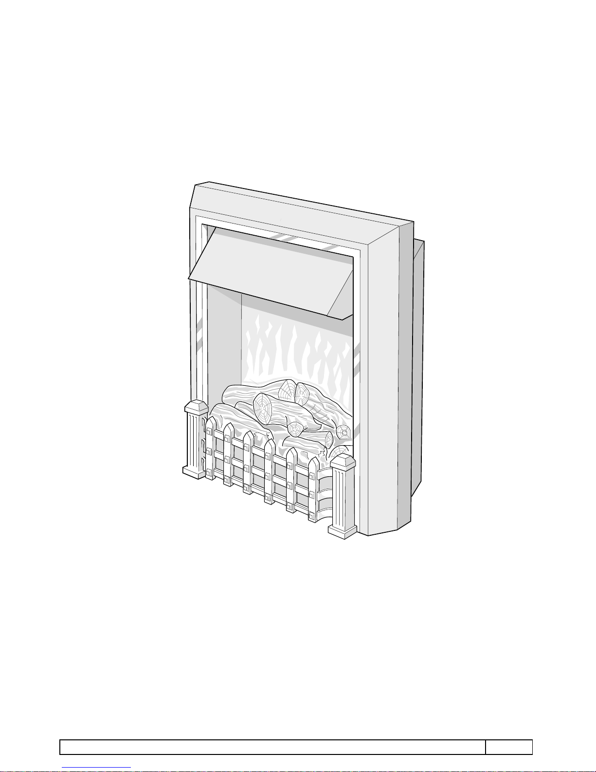
Shaftsbury SHA20
Page 2
01/02 SHAFTSBURY SHA20 PAGE 2
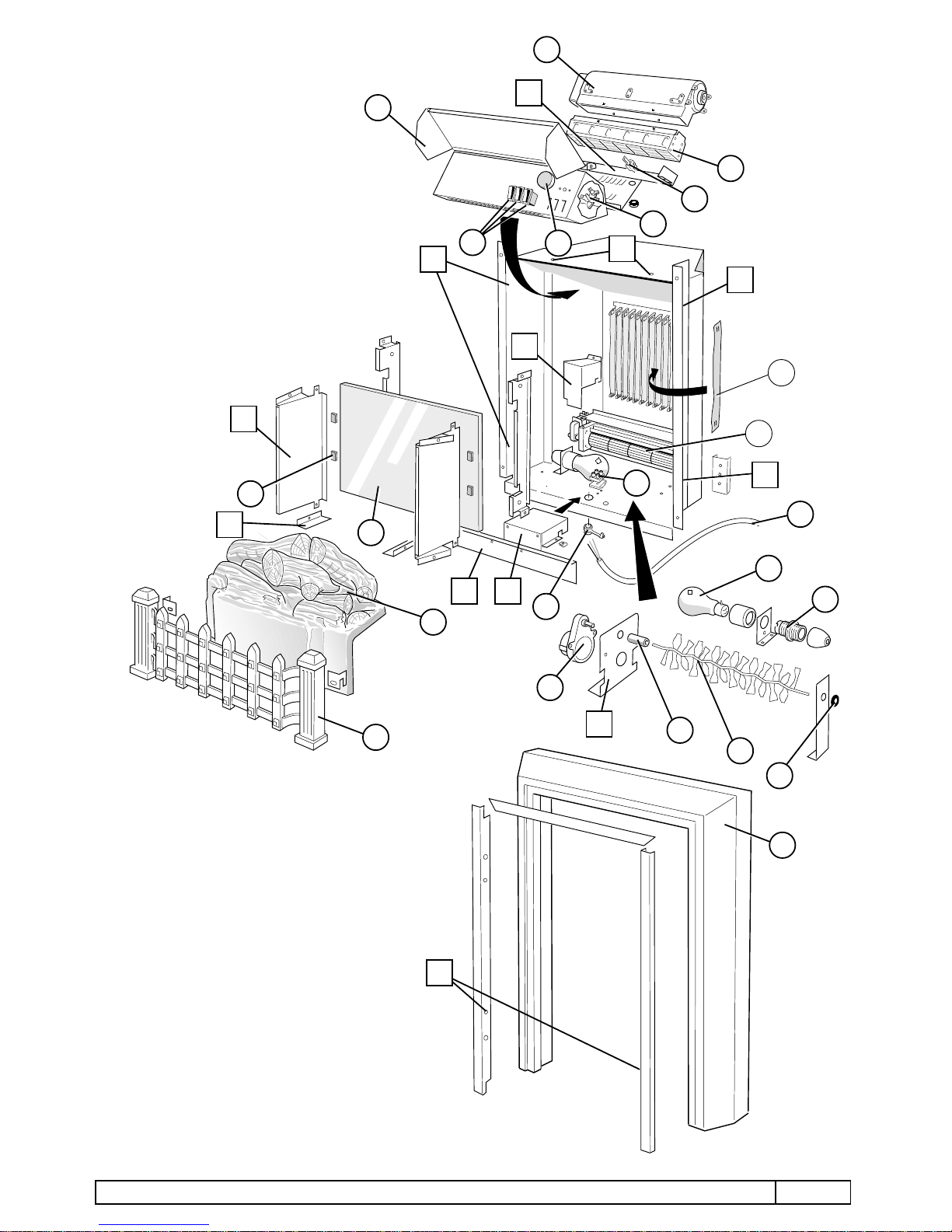
Dimplex – SHAFTSBURY
18
20
3
4
5
19
7
2
16
17
11
21
F
BC
Shaftsbury SHA20
1
6
D
9
10
8
13
12
14
15
A
E
H
22
G
Y
X
X
X
??
Page 3

01/02 SHAFTSBURY SHA20 PAGE 3
TECHNICAL DATA
Model SHA20
Colour Black & Brass
Country of Origin Irish Republic
Fuel Effect Optiflame Elite (log)
Heat Source Fan Heater
Thermostat Bi-metal leaf
Electrical Supply 230- 240 Volts 50 Hz AC
Total Loading: 1956-2136 Watts
Elements: 1820-2000 Watts
Lamps: 2 x 60 Watts BC Lamps
Motors: 2 x 6.5 Watts, 1 x 2.5 Watts
SERVICING AND DISMANTLING INSTRUCTIONS
ENSURE APPLIANCE IS DISCONNECTED FROM THE ELECTRICITY SUPPLY BEFORE DISMANTLING.
NOTE ALL CONNECTION DETAILS AND ROUTING OF LEADS BEFORE DISMANTLING.
ALWAYS REPLACE CABLE TIES ON RE-ASSEMBLY.
Numbers appearing in the text refer to illustrations and parts list numbers.
LAMP REPLACEMENT
1.1 Grasp the grate 17 and lift it upward and away from the fire. Grasp the fuel effect and ease it out past
grate retaining screws at position "A", then lift it away.
1.2 Grip the defective lamp near its centre and rotate the lamp anti-clockwise until it comes out of its
holder. Replace the defective lamp with a 240V, 60W BC Fireglow lamp.
1.3 Reassemble, ensuring that the fuel effect sits correctly behind the grate retaining screws at position
"A", then refit the grate, engaging the hooked brackets over the two retaining screws.
MAINS CABLE
2.1 Remove the grate and fuel effect as detailed in 1.1 above, and lay the fire on its back on a soft surface.
2.2 Release the two screws securing terminal cover box "B", from underneath the chassis, and lift the box
away with light baffle "C" attached.
2.3 Disconnect the live and neutral leads from terminal block 22 and the earth screw assembly. Release
cable clamp arm 11 by squeezing the barbs from inside the chassis. Use a pair of long-nosed pliers to
squeeze the cable clamp locking tab and withdraw the clamp 11 and cable 12.
2.4 Reassemble, ensuring that wires are not trapped by the terminal cover box.
LOG FLAME EFFECT
3.1 Remove the grate and fuel effect and terminal cover box "B" as detailed in 2.1 and 2.2 above.
3.2 Detach the leads from rotisserie motor 12 to the terminal block 1. Cut cable ties where necessary to
thread the motor leads through the heat sleeving.
3.3 Release the two screws holding motor bracket "E", grasp motor coupling 13 and withdraw motor 12.
Flames rotisserie 14 is also a push fit on coupling 13 and the other end sits loosely in grommet bush
15.
3.4 To detach the motor, release the two bright screws attaching it to the motor bracket.
3.5 Reassemble in reverse order, ensuring that cable ties are replaced where necessary and that no wires
are trapped by the terminal cover box. Check that the rotisserie rotates without obstruction before
refitting the fuel effect.
Page 4

01/02 SHAFTSBURY SHA20 PAGE 4
L
E
N
60W
LAMP
60W
LAMP
ROTALINK
10 RPM
CUT-OUT
I
II
O
123
1
HEAT
FAN1KW
III
1KW
2
3
M
EFFECT
FAN
REAR FLAME EFFECT
4.1 Remove the grate and fuel effect and terminal cover box "B" as detailed in 2.1 and 2.2 above.
4.2 Remove glass retaining panels "F", each secured by two screws inside and one outside the chassis, and
lift mirrored glass 19 clear.
4.3 Remove motor guard "G", secured by one screw from the rear and one from undermeath the chassis.
4.4 Blower unit 8 is secured by four screws, from the underside of the chassis.
4.5 Connections are by push-on terminals. Note positions before disassembling.
4.6 Cloth flags hook onto supports at top and bottom. Ensure all flags hang freely.
4.7 Reassemble in reverse order, ensuring that cable ties are replaced where necessary and that no wires
are trapped by the terminal cover box.
FAN HEATER AND CONTROLS
5.1 Remove the log effect, and lay the fire on its back on a soft surface.
5.2 Remove the mirrored glass, as detailed in 4.2 above.
5.3 Stand the fire back up and remove the four screws at position "X", securing the surround to the chassis
and lift the surround away.
5.4 Remove the two screws near the top of the rear panel and, whilst supporting the fan heater assembly,
the two screws at position "Y" in the top of the chassis securing the fan heater assembly. The heater
assembly can now be positioined in front of the chassis to the extent of the connecting leads.
5.5 Canopy hood 21 is secured by pop rivets. Drill out the rivets, and on reassembly replace with rivets size
M3.2 - 6.5mm.
5.6 Heat blower unit 3 is secured to the control panel by four screws. Element 4 is secured to the blower unit
by four screws and cut-out 5 is secured to the element by a single screw.
5.7 The switches are a push fit; compress the clips on the switch body and ease the switch 1 forward and
out. Note connections before disconnecting push-on terminals.
5.8 Thermostat 6 is secured by two screws through the control panel; pull off control knob 2 to access the
screws.
AFTER SERVICING, IT IS RECOMMENDED THAT THE PRODUCT IS TESTED FOR INSULATION AND
EARTH CONTINUITY, IN ACCORDANCE WITH RELEVANT LOCAL SAFETY REGULATIONS.
THEORETICAL WIRING DIAGRAM – SHA20
Page 5

PARTS LIST
SHAFTESBURY SHA20 LOG
ITEM CAT NO WATTS VOLTS DESCRIPTION COLOUR MODEL
1 BF7211 SWITCH
2 FP00012 CONTROL KNOB
3 FP9557 BLOWER UNIT HEAT SER A
FP01072 BLOWER UNIT HEAT SER B - D
FP03029 BLOWER UNIT HEAT SER E
4 FP9410 2000 230/240 ELEMENT ASSY SER A
FP01073 2000 230/240 ELEMENT ASSY C/W CUT OUT SER B - D
FP03030 2000 230/240 ELEMENT ASSY C/W CUT OUT SER E
5 FB9402 CUT OUT SER A
6 BF9433 THERMOSTAT
7 FP01003 CLOTH FLAGS x 10
8 FP00003 BLOWER UNIT
9 BF7223 60 LAMPS RED
10 BF7226 LAMPHOLDER
11 FP9005 CABLE CLAMP
12 FP9929 GEARED MOTOR 10RPM
13 FP20007 MOTOR COUPLING
14 FP20005 ROTISSERIE FLAMES
15 FP9554 RUBBER GROMMET
16 FP01094 SURROUND ASSY
17 FP01096 GRATE ASSY
18 FP01095 LOG EFFECT
19 FP01084 MIRRORED GLASS
20 FP9605 GLASS RUBBER BUFFERS
21 FP01058 CANOPY HOOD
22 BU9502 TERMINAL BLOCK
03/04 SHAFTESBURY SHA20 LOG PAGE 198
Page 6

01/02 SOMERLEY SOM20
Somerley SOM20
Page 7

01/02 SOMERLEY SOM20
Dimplex – SOMERLEY
16
18
3
4
5
17
7
2
13
14
11
19
E
Somerley SOM20
1
6
D
9
10
8
15
A
20
Y
X
X
X
F
C12B
Page 8

01/02 SOMERLEY SOM20
TECHNICAL DATA
Model SOM20
Colour Black & Brass
Country of Origin Irish Republic
Fuel Effect Optiflame Plus (Real Coal)
Heat Source Fan Heater
Thermostat Bi-metal leaf
Electrical Supply 230- 240 Volts 50 Hz AC
Total Loading: 1956-2136 Watts
Elements: 1820-2000 Watts
Lamps: 2 x 60 Watts BC Lamps
Motors: 2 x 6.5 Watts, 1 x 2.5 Watts
SERVICING AND DISMANTLING INSTRUCTIONS
ENSURE APPLIANCE IS DISCONNECTED FROM THE ELECTRICITY SUPPLY BEFORE DISMANTLING.
NOTE ALL CONNECTION DETAILS AND ROUTING OF LEADS BEFORE DISMANTLING.
ALWAYS REPLACE CABLE TIES ON RE-ASSEMBLY.
Numbers appearing in the text refer to illustrations and parts list numbers.
LAMP REPLACEMENT
1.1 Remove coal as necessary, then grasp the grate/fuel effect assembly 15, 16 and lift it upward and
away from the fire.
1.2 Grip the defective lamp, push in and twist it anti-clockwise to release it from its holder. Replace the
defective lamp with a 240V, 60W BC Fireglow lamp.
1.3 Reassemble, ensuring that the grate/fuel effect assembly engages the hooked brackets over the two
retaining screws at position “A”.
MAINS CABLE
2.1 Remove the grate/fuel effect assembly as detailed in 1.1 above, and lay the fire on its back on a soft
surface.
2.2 Release the two screws securing terminal cover box "B", from underneath the chassis, and lift the box
away with light baffle "C" attached.
2.3 Disconnect the live and neutral leads from terminal block 20 and the earth screw assembly. Release
cable clamp arm 11 by squeezing the barbs from inside the chassis. Use a pair of long-nosed pliers to
squeeze the cable clamp locking tab and withdraw the clamp 11 and cable 12.
2.4 Reassemble, ensuring that wires are not trapped by the terminal cover box.
FLAME EFFECT
4.1 Remove the grate/fuel effect assembly and terminal cover box "B" as detailed in 2.1 and 2.2 above.
4.2 Remove glass retaining panels "E", each secured by two screws inside and one outside the chassis,
and lift mirrored glass 17 clear.
4.3 Remove motor guard "F", secured by one screw from the rear and one from undermeath the chassis.
4.4 Blower unit 8 is secured by four screws, from the underside of the chassis.
4.5 Connections are by push-on terminals. Note positions before disassembling.
4.6 Cloth flags 7 hook onto supports at top and bottom. Ensure all flags hang freely.
4.7 Reassemble in reverse order, ensuring that cable ties are replaced where necessary and that no wires
are trapped by the terminal cover box.
Page 9

01/02 SOMERLEY SOM20
L
E
N
60W
LAMP
60W
LAMP
CUT-OUT
I
II
O
123
1
HEAT
FAN1KW
III
1KW
2
3
EFFECT
FAN
FAN HEATER AND CONTROLS
5.1 Remove the grate/fuel effect assembly, as detailed in 1.1 above, and lay the fire on its back on a soft
surface.
5.2 Remove the mirrored glass 17, as detailed in 4.2 above.
5.3 Stand the fire back up and remove the four screws at position "X", securing the surround to the chassis
and lift the surround away.
5.4 Remove the two screws near the top of the rear panel and, whilst supporting the fan heater assembly,
the two screws at position "Y" in the top of the chassis securing the fan heater assembly. The heater
assembly can now be positioined in front of the chassis to the extent of the connecting leads.
5.5 Canopy hood 21 is secured by pop rivets. Drill out the rivets, and on reassembly replace with rivets size
M3.2 - 6.5mm.
5.6 Heat blower unit 3 is secured to the control panel by four screws. Element 4 is secured to the blower unit
by four screws and cut-out 5 is secured to the element by a single screw.
5.7 Switches 1 are a push fit; compress the clips on the switch body and ease the switch forward and out.
Note connections before disconnecting push-on terminals.
5.8 Thermostat 6 is secured by two screws through the control panel; pull off control knob 2 to access the
screws.
AFTER SERVICING, IT IS RECOMMENDED THAT THE PRODUCT IS TESTED FOR INSULATION AND
EARTH CONTINUITY, IN ACCORDANCE WITH RELEVANT LOCAL SAFETY REGULATIONS.
THEORETICAL WIRING DIAGRAM – SOM20
Page 10

PARTS LIST SOMERLEY SOM20
ITEM CAT NOWATTSVOLTS DESCRIPTION COLOUR MODEL
1 BF7211 S/P SWITCH
2 FP00012 CONTROL KNOB PRINTED GOLD
3 FP9557 HEAT BLOWER UNIT SER A
FP01072 HEAT BLOWER UNIT SER B - C
FP03029 HEAT BLOWER UNIT SER D
4 FP9410 2000 230/240 ELEMENT SER A
FP01073 2000 230/240 ELEMENT C/ CUT OUT SER B - C
FP03030 2000 230/240 ELEMENT C/ CUT OUT SER D
5 FB9402 CUT OUT (OTTER V-10) SER A
6 BF9433 THERMOSTAT
7 FP01003 CLOTH FLAGS
8 FP00003 EFFECT BLOWER UNIT
9 BF7223 60 LAMPS FIREGLOW RED
10 BF7226 LAMPHOLDER
11 FP9005 CABLE CLAMP
12 FP20020 PLUG & LEAD ASSY
13 FP01057 SURROUND ASSY
14 FP01034 COAL PACK
15 FP00056 GRATE ASSY
16 FP00055 FUEL EFFECT
17 FP01084 REAR GLASS
18 FP9605 RUBBER GLASS BUFFERS
19 FP01058 CANOPY HOOD
20 BU9502 2 WAY TERMINAL BLOCK 16AMP
02/04 SOMERLEY SOM20 PAGE 203
 Loading...