

Page 1
SERVICE POLICY/GUARANTEE
Shower User Guide
Before telephoning the Dimplex Customer Service Department you should
ensure that you have the model number, power rating, serial number and
date of purchase.
If the product is no longer covered by the Guarantee, a charge will be made
for the site visit and for any parts supplied.
A charge will be made where a call under the terms of the guarantee has
been booked and a failure was not product related, or an engineer arrives
and is not able to gain access.
If a service call is booked, you or a representative must be present during the
Engineers visit.
The Dimplex Customer Service Department will be able to inform you whether
the fault can be rectified by the provision of a replacement part or an on site
visit by a Qualified Service Engineer.
In the event of you needing to contact the Dimplex Customer Service Department,
the following procedure should be followed:-
Glen Dimplex Limited guarantee this product for a period of two years, from date of purchase,
against mechanical and electrical defects arising from faulty materials or manufacturing defects,
providing the product has been installed by a competent person in accordance with the
fitting instructions.
Glen Dimplex Limited undertake to repair or replace, at their discretion, without charge,
provided the product has been properly maintained and operated in accordance with the
operating instructions. Any component found to be defective during this period, as the result
of misuse or damage, or the effects of scaling, will not be covered by this guarantee.
This product must not be modified, repaired or taken apart except by a person authorised by
Glen Dimplex Limited.
This Guarantee is only valid within the United Kingdom and does not cover product used commercially.
This Guarantee does not affect your statutory rights.
Glen Dimplex UK Limited, Millbrook House, Grange Drive, Hedge End, Southampton SO30 2DF.
Tel 0870 077 7117 Fax 0870 727 0109
Customer Services Tel 0870 240 9402
1
2
3
4
5
GUARANTEE
Dimp13292-Shower inst aX4 5/5/04 2:08 pm Page 1
Page 2
SECTION 1
Unpacking and important notices
Contents
1 x Shower Unit
1 x Showerhead
1 x Flexible Hose
1 x Slider Rail Tube
1 x Slider Rail Brackets
1 x Height adjuster
1 x Screw pack
1 x Soap dish
1 x Showerhead key
IMPORTANT NOTICES
PLEASE READ BEFORE ATTEMPTING
TO INSTALL THE SHOWER UNIT
1) The shower unit must be installed by a
suitably qualified person and conform
to IEE Regulations and National Water
Council Bylaws.
2) The shower must only be connected
to a 15mm mains cold water supply.
Do not connect the unit to the cold
water supply of a header tank.
3) The minimum recommended running
water pressure to which the shower
heater may be connected is 15lb/sq in
(1bar); running pressure of 8 litres/minute;
maximum static pressure recommended
150lb/sq in (10 bar).
4) The shower unit must not be fitted
where it may be exposed to frost, for
example in an outdoor shower area. The
shower must not be used if suspected of
being frozen. Please note: Frost damage
is not covered by the guarantee.
5) Do not use Plumbers jointing compound.
Use of plumbers jointing compounds
invalidates the guarantee.
Complete all plumbing connections
before making any electrical connections.
The outlet of the shower unit must only be
connected to the hose and showerhead
supplied with the unit. Use of other
components will invalidate the warranty.
Always switch off at the isolating switch
when the shower is not in use.
To comply with National Water Council
bylaws a double check valve must be
fitted where it is possible that the showerhead may come into contact with used
water e.g. in the shower tray or bath.
Do not operate power tools in a wet environment. It is recommended that any power
tools operated in the bath or shower area are
supplied via a Residual Current Device (RCD).
WARNING! THIS APPLIANCE MUST BE EARTHED.
This shower is for connection to a
230V-240V/50Hz mains electricity supply.
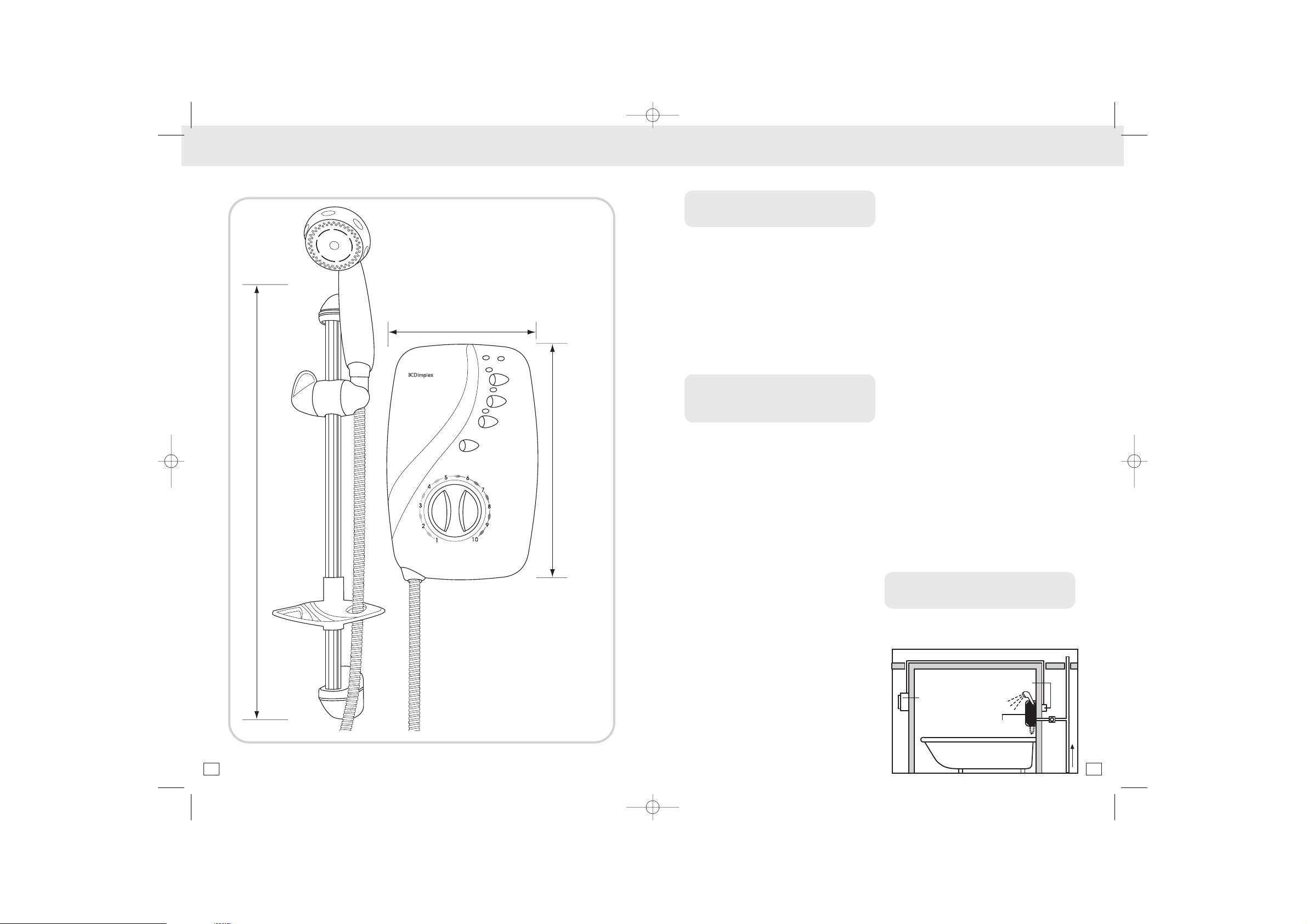
SECTION 2
Installation
Typical instantaneous electric shower
installation
DIMENSIONS UNPACKING AND IMPORTANT NOTICES / INSTALLATION
HIGH
LOW
COLD
LOW
PRESSURE
AUTO
RESET
TEMPERATURE
S
T
O
P
610mm
218mm
339mm
2 3
Dimp13292-Shower inst aX4 5/5/04 2:08 pm Page 3
Double pole heater switch wall mounted in
accordance with local authority regulations
Seperate permanently
connected supply
from consumer unit
Dimplex electric
water heater
Isolating
stop tap
Cold
water
mains
supply
Page 3

Planning the installation
The shower should be located in a position
where walls are protected from water and
sufficient drainage is provided.
1) Consideration should be given to the
location of the nearest cold mains
water supply and the routing of this
to the shower. The shower will accept
a mains supply from the bottom,
back or top of the unit. Remove the
appropriate plastic plate from the
back plate before commencing
installation.
2) Avoid connecting the shower unit
where it will be affected by water
drawn off by other appliances, e.g.
from the mains feed to the W.C. This
may cause a drop in pressure too low
for the shower unit to work correctly.
General
1) Fit an isolating valve to the mains
water supply so that the shower can
be serviced.
2) The shower unit is best placed to the
right hand side of the riser rail and
placed so that the top of the unit sits
alongside the middle to top of the riser
rail. This reduces the amount of water
falling on the unit.
The top of the riser rail should be sited
to coincide with the height of the tallest
person using the shower.
Before drilling any holes check that
there are no hidden cables or pipes
below the surface to be drilled.
To avoid loss of small parts cover any
drainage holes.
3) The shower unit should be positioned
so that the showerhead cannot be
immersed in the bath or shower tray
when hanging down.
Where holes are to be drilled into a
tiled surface a suitable tile or glass drill
bit should be used to make a hole
through the tile only. The hole made
through the tile should be 0.5mm larger
than the hole in the wall.
These installation instructions assume
mounting onto a solid masonry wall.
For other types of structure please
amend the procedure accordingly.
Plumbing
1) Remove the front cover of the shower
unit complete with the two control knobs
by removing the two screws securing it to
the back plate. Remove the ‘trim plate’ at
the bottom right-hand side of unit to
allow easy access for the plumbing work.
2) Position the shower unit on the wall in
the desired place and mark the location
of the fixing holes.
3) Determine the direction of the inlet water
supply: bottom (rising), top (falling) or
back inlet. The shower unit is supplied
with a swivelling push-fit inlet elbow. This
elbow should be rotated to match the
desired direction of water supply entry to
the unit. Carefully remove the appropriate
plastic break-out from the unit’s back
plate so that the mains water supply
pipe can be routed into the unit.
4) Carefully drill the holes using a 5.5mm
masonry drill (note when drilling though
tiles first use a glass or tile drill bit of 6mm
diameter to drill a hole through the tile).
5) Insert the plugs provided through the
hole in the tile and fix the unit to the
wall using the screws supplied. Do not
tighten the screws fully at this stage.
6) Turn off the water supply at the isolating
stop tap.
7) Bring the mains water supply using
15mm copper or stainless steel pipe to
the shower unit so that it enters through
the hole in the back plate.
8) Before connecting the shower unit, flush
out any debris in the new pipework by
connecting a hose to the end of the
mains supply pipe and running the mains
water until all the debris has cleared.
9) After flushing out, turn off the
water supply and connect
the pipe to the shower inlet.
Having inserted the inlet
pipe into the elbow, secure
the joint by finger tightening
the locking device, rotating
in a clockwise direction.
10)Make sure that the shower unit is
positioned squarely on the wall and
tighten the fixing screws. Tighten all
plumbing joints and turn on the water
supply to check for leaks. With the unit
firmly fixed to the wall and the pipework
free from leaks, dry the shower area in
preparation for the electrical
installation.
INSTALLATION INSTALLATION
4 5
Dimp13292-Shower inst aX4 5/5/04 2:08 pm Page 5
Product Positioning Guide
LOW
AUTO
PRESSURE
RESET
COLD
LOW
HIGH
P
O
T
S
TEMPERATURE
Page 4

Riser rail
Part the mounting bracket
assembly so that the fixing plate
is separate from the cover.
Establish the best position for the
riser rail, and mark the wall for
the lower mounting bracket.
Make allowances for the tallest person likely to
use the shower regularly.
When drilling through tiles use a
suitable glass or tile drill of 6mm
diameter to drill through the tile
only. Use a no 10/5.5mm masonry
drill to make a hole 35mm deep,
and fit the wall plug. (NB some
wall constructions may require the use of
different types of wall fixings to those supplied).
Screw the lower bracket base to the wall.
Locate the crimped end of
the riser rail (Figure 4) into the
mounting bracket, then fit
the upper bracket to the rail.
Ensure the rail is vertical, then
mark the wall for the fixing.
NOTE if it is necessary to
shorten the rail, use a junior
hacksaw to cut the excess
material from the plain end
of the rail (the uncrimped
end).
Insert the end pieces of the
height adjuster into the body
section matching the letters A
and B (moulded into the ends
of each piece) and twist so the
pieces lock together.
With the shower head holder in
the upright position (widest
opening at the top) and the
lever in the open position, slide
the assembly onto the rail.
Tighten the height adjuster to
the rail by twisting the lever.
Insert the rail into the bottom
and top brackets and screw
the upper mounting bracket
in place. Clip the end caps
onto the mounting brackets.
Electrical
Switch off the water supply at the isolating
valve before connecting the wiring to the
unit.
The shower unit must be permanently
connected to the electricity supply, direct
from the consumer unit via a double pole
linked switch with a minimum contact gap
of 3mm.
It is recommended that the switch be a
cord operated type with neon on/off
indicator, otherwise the switch should be
readily accessible, clearly identifiable and
out of reach of any person using the shower.
The wiring to the switch must be done
without the use of a plug or socket outlet.
The cable used must be of a diameter
suitable for the power rating of the
shower selected. The table below may
be used as a guide to the cable
requirements. If in doubt consult a
qualified electrician.
kW rating Minimum Fuse rating Max cable length
Isolating switch (Amps) (Amps) Consumer unit to
shower (m)
6mm cable 10mm cable
7.5 40 40 27 44
8.5 40 40 23 38
9.5 40 40 21 32
10.5 45 45 18 30
2
3
4
5
6
1
7
INSTALLATION INSTALLATION / FINAL ASSEMBLY AND COMMISSIONING
The cable should be routed to the shower
unit from either the top, bottom or back
of the shower unit. This cable should be
hidden from view.
Connect the brown live wire to the terminal
marked L
Connect the blue neutral wire to the terminal
marked N
Connect the yellow and green earth
wire to the terminal marked E on the
backplate.
IMPORTANT – ensure the terminal block
screws are fully tightened and that no
insulation enters the terminal block,
preventing a good electrical connection.
To conform to IEE regulations the earth
continuity conductor of the electrical
installation must be effectively connected
to all exposed metal parts of other
appliances and services in the room in
which the shower unit is installed.
WARNING! Do not attempt to operate
the shower unit until the installation is
fully complete.
SECTION 3
Final assembly and commissioning
With the unit wired and plumbed correctly
the front cover may now be refitted.
1) Place the cover lightly over the shower
unit and turn the knobs so that they
engage correctly with the spindles.
The front cover may then be pressed
lightly into place and secured using the
two fixing screws.
2) Fit the flexible hose to the shower unit
and remove the showerhead.
3) Turn the temperature control knob at
the bottom of the unit fully
anti-clockwise.
4) Turn on the power at the isolating
switch.
5) Start the shower by pressing the cold
power selector button. The water
should now begin to flow through the
shower.
Warning do not attempt to select any other
setting other than Cold at this stage.
6) Once a steady stream of water is
achieved from the outlet of the shower
unit stop the shower by pressing the
STOP button.
7) Pass the hose through the hole in the
soap dish and refit the shower head.
8) Fit the handset into the height adjuster
and clip the soap dish onto the riser
rail.
The unit is now ready for commissioning.
Commissioning the shower
Important: The shower unit must be full of
water before power (heat) settings are used.
1) With the water supply to the unit turned
on, turn the bottom temperature
control knob anti-clockwise to the full
cold position. No water should exit the
shower either from the handset or from
any other part of the shower unit.
6 7
Dimp13292-Shower inst aX4 5/5/04 2:08 pm Page 7
Page 5

2) Switch on the electrical supply at the
double pole isolating switch, the power
neon on this switch should light.
3) Start the shower by pressing the ‘Cold’
power selector button. Water should
start to flow from the handset within a
few seconds. The water will be at full
force and will run cold.
4) Now press the ‘Low’ power selector
button. Allow a few seconds for the
warmer temperature to reach the
showerhead – this shows that the ‘Low’
power is operating correctly.
5) N
ow press the ‘High’ power selector
button. The temperature at the shower
head will rise further – this shows that
the full power setting is operating
correctly.
6) Turn the bottom temperature control
knob clockwise for hotter water and
anti-clockwise for cooler water. Allow
a few seconds between selections for
the temperature change to reach the
showerhead. Note that selecting a
hotter setting in the temperature
control reduces the flow of water.
7) Press the STOP button to stop the water
flow. Water should continue to flow,
eventually running cool before
switching off.
A small amount of water may continue to
drip from the unit as water drains from the
pipe-work. This should stop within a few
minutes.
The commissioning procedure is now
complete.
SECTION 4
Operation
‘Power indicator’:
The power indicator on the shower unit
will light when the shower is switched
on and water is flowing on one of the
two heat settings. The indicator does
not light on the cold setting.
‘Auto Reset Indicator’
The Auto Reset Indicator will illuminate if
an overheat temperature is sensed
during operation. Once activated the
electricity supply to the elements is
switched off until the unit has cooled
sufficiently, where upon power to the
elements will be restored.
‘Low Pressure Indicator’
The low pressure indicator will
illuminate if the mains water supply
pressure falls below the minimum
level. The heat settings will be
disabled until normal operating
pressure is restored.
1) Switch on using the pull-cord or wall
mounted switch.
2) To start the shower, turn the temperature
dial to the desired number and press
the desired power button, upon which
water will start to run through the
shower.
3) The shower has three positions
‘Cold’, ‘Low’ power and ‘High’ power.
‘Cold’ setting:
Adjustment of the flow control on this
setting will only alter the flow of water
not the temperature.
FINAL ASSEMBLY AND COMMISSIONING / OPERATION OPERATION / LOOKING AFTER YOUR SHOWER
‘Low’ setting:
This is the low power setting for economy
during warmer months or when a
cool shower is required.
‘High’ setting:
This is the full power setting.
4) If necessary turn the bottom ‘temperature’
control knob slowly to obtain the desired
showering temperature. Waiting a few
seconds after each adjustment for the
temperature to stabilise.
To increase the shower temperature
Turn the temperature control knob
clockwise, this will decrease the flow
of water and increase the shower
temperature.
To decrease the shower temperature
Turn the temperature control knob
anti-clockwise, this will increase the flow
of water and decrease the shower
temperature.
5) To stop the shower press the STOP button.
Allow the water to run until it stops
automatically
6) Switch off the electricity supply using
the pull-cord or wall mounted switch.
SECTION 5
Looking after your shower
The showerhead should be cleaned
periodically to remove limescale or other
particles which will reduce the performance
of the shower. The frequency of cleaning
will vary according to the local water
quality. In hard water areas cleaning will
be needed more often than in soft water
areas. A liquid non-abrasive bathroom
HIGH
LOW
COLD
LOW
PRESSURE
AUTO
RESET
TEMPERATURE
S
T
O
P
Cooler Warmer
TEMPERATURE TEMPERATURE
8 9
Dimp13292-Shower inst aX4 5/5/04 2:08 pm Page 9
LOW
PRESSURE
COLD
AUTO
RESET
LOW
HIGH
P
O
T
S
Page 6

cleaner may be used on external surfaces
of the handset. Rub-clean showerheads
may be rubbed lightly to remove scale as
required. Over time build-up of limescale
requires the showerhead to be cleaned
more thoroughly, as follows.
1) Use a liquid non-abrasive bathroom
cleaner on external surfaces of the
handset.
2) Engage the key into the spray cartridge
recesses and turn anti-clockwise to
unscrew.
3) Remove the two small black ‘O’ rings
from the rear of the spray cartridge,
and rinse the ‘O’ rings clean.
4) Brush the spray plate with a stiff bristled
brush, if necessary immerse and soak
the spray plate for several hours in a
proprietary limescale remover. Rinse off
all traces of limescale and limescale
remover from the showerhead.
5) Replace the two black ‘O’ rings on the
rear of the spray cartridge and refit the
cartridge to the showerhead tightening
with the key.'
SECTION 6
Trouble shooting
Before calling our customer service
department please use the table to
determine likely causes of the problem:
NOTE Under normal operation the shower
heats the water as it passes through the
unit. The temperature of the water is
affected by the temperature of the water
in the mains cold water supply and the
speed with which the water flows through
the unit. It is therefore normal for the water
coming out of the shower to change
temperature through summer and winter
months where the mains water
temperature changes. It is also normal
for the water temperature to vary when
other water appliances are being use in
the home as these vary the water flow to
the shower unit. Do not under any
circumstances cover the showerhead
or prevent or restrict water leaving the
showerhead or unit. It is important to keep
the showerhead clean, removing all lime
scale and any other dirt blocking the
holes of the showerhead. The showerhead
must be cleaned as described in section
5 ‘looking after your shower’.
SECTION 7
Maintenance
Disconnect from mains electricity supply
before removing front cover.
All maintenance should only be carried
out by a qualified service engineer.
LOOKING AFTER YOUR SHOWER / TROUBLESHOOTING / MAINTENANCE TROUBLESHOOTING
SYMPTOM
No hot water
Power indicator is
not lit
Water too hot
Water too cool or cold
Water flow is poor
Water continues to
drip from the handset
when switched off.
Pressure relief device
has operated
(water ejecting from
Pressure Relief tube).
POSSIBLE CAUSE
Power setting is at Cold.
Low Water Pressure.
The thermal cut-out
has operated.
The power setting is on cold.
Water pressure below minimum required.
Not enough water flowing through the
shower.
Blockage in supply.
Increase in ambient water
temperature.
Wate r flow too high.
Water pressure below minimum
required (See rating label).
Reduction in ambient water
temperature.
Shower head is blocked
The temperature control knob is
set at its hottest setting.
Water is draining from the shower unit,
after use.
Blocked spray head.
Twisted/blocked flexible shower hose.
ACTION
Select a heat setting
The water supply has dropped below the
minimum operating pressure. Switch off other
cold water devices and retry.
Clean the showerhead, and restart the shower.
If no hot water is produced call the Dimplex
Service Centre.
Select a heat setting and the indicator should
light.
Check if water mains stop valve is fully open.
Increase flow rate via temperature control.
Blocked spray head - clean or replace blocked
spray plate in spray head.
Check if stop valves are fully open. Check for
blockage in inlet filter.
Re-adjust flow rate to give increased flow.
Select ‘Low’ power.
Reduce flow rate via temperature control.
Select ‘High’ power.
Clean the showerhead. Ensure showerhead is as
specified by manufactured.
Increase the power setting by selecting hot and
increase the flow using the temperature control
knob.
This is normal, no action required. Should
water continue to drip after a few minutes
contact Dimplex Service Centre.
Remove handset and run water through the
shower and hose to remove any dirt that may
be trapped in the system. Clean or, if possible,
replace the spray plate in the spray head and
then fit a new Pressure Relief Device.
Check the hose is not restricted anywhere along
its length. Replace the hose if necessary and fit
a new Pressure Relief Device.
10 11
Dimp13292-Shower inst aX4 5/5/04 2:08 pm Page 11
 Loading...