

Dimplex EPX 500, EPX 2500, RX TI 24, RX PW 1, RX TI RB Instructions For Installation And Use Manual
...Page 1

INDPGEELRG Issue 0
Montage- und Gebrauchsanweisung
Instructions for Installation and Use
Instructions de montage et de service
EPX 500 ... EPX 2500 Wandkonvektor
Convector Heater
Convecteur de Base Mural
RX TI 24 24 Stunden Programmierkassette
24-Hour Programming Cassette
Cassette de programmation 24 heures
RX PW 1 7 Tage Programmierkassette
7-Day Programming Cassette
Cassette de programmation 7 jours
RX TI RB Ablauf Timer
Runback Timer
Programmateur minuterie
Page 2
Installation and Operating Instructions
EPX 500 – EPX 2500 Wall-Mounted Convector 453321.67.95gb 02/06/A
1. Important Information
Read all information contained in this manual carefully. Keep
these instructions in a safe place and pass them on, if
applicable, to the next owner or user.
- The heater may only be installed by a qualified person.
- The heater may only be used for heating room air in
enclosed spaces.
- All repairs and interventions in the appliance may only be
performed by a qualified electrician.
- In the event of any defect or during extended periods of
non-use, the heater must be disconnected from the power
supply. Deactivate or remove fuse.
- Do not cover the heater as there is a risk of
fire!
- Caution! The outside of the appliance gets
hot when in use.
- The appliance is not intended for use by children or other
persons not capable of using the heater in a safe manner.
Children must be prevented from playing with the
appliance.
- Do not insert any object through the heater inlet and outlet
openings.
- Do not use the heater in areas where flammable
substances are stored or used (e.g. solvents, etc.).
- Keep the mains lead away from the hot body of the heater.
- Caution! If the appliance is switched on automatically
while unattended, potential hazards may exist, e.g.
appliances that have been covered or obstructed in your
absence may pose a risk of fire.
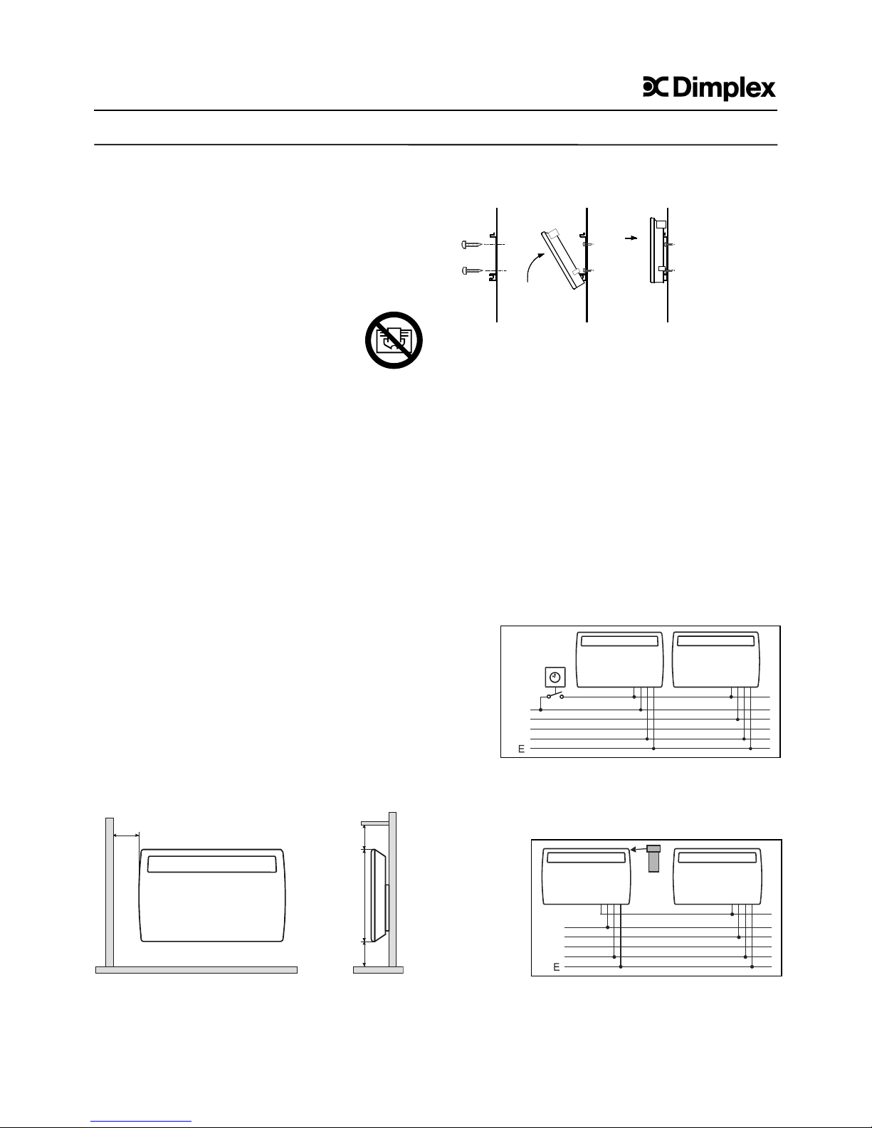
2. Mounting, Installation, Minimum Clearances
The heater must be installed in a horizontal position on a
vertical wall as shown in the illustration.
It must be ensured that the airflow is not obstructed by
keeping the air inlet and outlet openings at the bottom and the
top of the heater free
.
The heater must be installed in such a way that switches and
other controls cannot be touched by the person using the bath
or the shower.
Do not install the heater immediately below a power socket.
The electrical connection box must be accessible after the
heater has been mounted. Be careful of flammable objects!
It is absolutely necessary that the minimum clearances
indicated in the mounting diagram be maintained. Beyond
that, a clearance space of at least 500 mm is to be allowed in
front of the appliance.
Wall Mounting
IMPORTANT- The original wall mounting bracket supplied,
located at the back of the heater, must be used.
- Drill the fixing holes for the wall mounting bracket.
- Firmly secure bracket to the wall using suitable screws.
- Insert heater in wall bracket making use of the slots on the
back of the heater.
- Snap heater in place at the top of the wall bracket.
3. Electrical Connection
It is imperative that the current regulations acc. to VDE 0100
Part 701 as well as the relevant installation instructions be
adhered to. The heaters are fitted with a power supply cable
without plug. The supply cord must be connected to a
connection box dedicated to the heater. The hardwired
electrical installation must be provided with a disconnect
device with a contact gap of at least 3 mm at each pole (e.g.
automatic circuit breaker).
3.1 Temperature Setback Using a Pilot Wire
To set back the temperature adjusted on the thermostat (by
5° C) the black pilot wire circuit is controlled by an external
electrical contact with any phase , e.g. a timer. Any ancillary
appliances connected via the pilot wire are controlled in the
same way.
3.2 Automatic Turning On and Off
If a programming cassette (accessory) is used for automatic
switching on and off, any additional appliances which are
connected to the black pilot wire will be controlled in the same
manner.
The pilot wire does not have to be in phase with the mains
connection. A maximum of 10 appliances can be operated via
a common pilot wire.
150
150
150
430
N
L1
L2
L3
N
L1
L2
L3
GB
Page 3

If the power cord of this heater is damaged, it must be
replaced.; a special new power cord is available from the
manufacturer or the after-sales service.
4. Heating Operation
The heater is switched on and off by means of the power
switch. The right indicator light (B) is illuminated when the
appliance is switched on.
MAX
*
Indicator light (A) Indicator light (B) Power switch
"Heating On“ "Device On“ On/Off
4.1 Thermostat
The heater is fitted with an electronic thermostat by means of
which the room temperature can be controlled by choosing a
suitable setting. The ∗ setting corresponds to a room
temperature of approx. 6 °C (frost protection setting). To
increase the temperature, move the slide switch to the right.
The left indicator light (A) is illuminated when the heater is in
the heating mode.
4.3 Limiting the Thermostat Setting Range
The setting range of the thermostat can be defined by means
of the two limiting pins (A) provided on the heater rear panel.
One pin each is provided for limiting the upper and lower
value.
The pins can be removed by moving them back and
forth, e.g. by means of flat nose pliers, and be inserted
into the holes in the thermostat.
5. Overheat Protection
The heater is equipped with an overheat protection for your
safety. If the air circulation is impeded, the heater is switched
off by the overheat protection. Once the heater has cooled
sufficiently, it will automatically switch on again.
In the event that the overheat protection trips repeatedly, the
cause of overheating must be determined, e.g. air grille is
covered or obstructed.
For maximum heat output it is essential that you keep the air
inlet and outlet openings free of dust. Clean the heater with a
vacuum cleaner before the start of the heating season!
6.Malfunctions
If there is no heat output from the unit, please check that the
heater is switched on and that the thermostat is set to the
desired temperature. Subsequently check the circuit breaker
on the main service panel, or the fuse, to ensure that they
have not tripped or blown.
When a programming cassette is used check that the
program "ON" is active (also refer to the operating instructions
of the programming cassettes on the pages that follow).
If the fault cannot be corrected, please consult the nearest
after-sales service agent.
For processing the service call, the product number (Enumber) and the manufacturing date code (FD-number) of the
heater are required. These data can be found on the rating
plate.
Any repairs and interventions in the heater may only be
performed by a qualified electrician or the after-sales service.
7. Cleaning
Before cleaning make sure that the heater is disconnected
from the power supply and that it has cooled down. Wipe the
outside of the heater with a soft, damp cloth. Do not use any
scouring powder or furniture polish for cleaning as these may
damage the surface.
Dust that may have accumulated in the heater can be
removed from the outside with a vacuum cleaner.
8. Technical Data
Supply voltage 1/N/PE~ 230V, 50Hz
Thermostat 5-30°C
Protection class I PE conductor
Enclosure type IP 24 (splash-water protected)
Type Capacity Weight Width HeightDepth Dim. A
(all dimensions in mm)
EPX 500 500 W 5.2 kg 448 430 115 116
EPX 750 750 W 6.6 kg 618 430 115 286
EPX 1000 1000 W 6.6 kg 618 430 115 286
EPX 1500 1500 W 7.1 kg 686 430 115 354
EPX 2000 2000 W 8.5 kg 858 430 115 526
EPX 2500 2500 W 10.5 kg 858 430 145 526
118
150
150
150
65
255
214
141
184
105
430
A
9. Warranty
Authorised dealers can provide information on the terms and
conditions of warranty. The warranty is not valid without a
sales receipt marked with the date of purchase.
Disposal Notice
The product should not be disposed of with your
other household waste.
Drilling dimensions (front view
)
Cable entry
Higher
temperature
Lower
temperature
A
Thermostat
Page 4

Installation and Operating Instructions
RX TI 24 24-Hour Programming Cassette 453321.67.97gb 02/06/A
1. Description
The programming cassette allows you to program within a
time frame of 24 hours up to 4 different time blocks during
which the heater is switched on. The programming cassette
can be used individually, i.e. for one heater, or serially, i.e.
for a group of heaters (e.g. for a complete dwelling unit).
If used as a serial programmer, a programming cassette is
installed in one heater. This unit acts as the so-called
"master control“. Once the electrical wiring (as shown in the
installation instructions of the heater) has been completed,
all time functions set on the master device will be followed
by every slave heater connected to the same circuit. The
heating program preset on the master control (time blocks
for On/Off) will also be executed on all slave heaters.
2. Installation
Switch off heater. Using a
narrow bladed screwdriver,
release the cover. Insert the
programming cassette fully
into the opening. If
necessary, the cassette can
be secured against
unauthorised removal by
means of the screw
supplied.
3. Setting the Time
Press the PROG button.
The "clock“ symbol
appears in the upper left
corner of the display and
the hours flash. Set the
hours using the ▼▲
buttons, confirm with
ENTER. Use the same
procedure to set the
minutes. Confirm with
ENTER.
4. Manual Switching On/Off Mode
Switch on the heater (indicator lamp is illuminated).
Press the MODE button
until MAN ON appears on
the display. The device is
switched on. If you wish to
switch the device off,
press MODE once more.
The display MAN OFF
appears. The device is
switched off.
5. Automatic Mode
Switch on the heater. Press the PROG button twice. P1 ON
appears on the display and the hours flash. Set the hours
using the ▼▲ buttons, confirm with ENTER. Use the same
procedure to set the minutes. Confirm with ENTER.
Note: Minutes can be set in 10-minute increments only!
P1 OFF now appears on the display. Set the desired switch-
off time and confirm with
ENTER. Program P1 has
thus been set. P2 now
appears, i.e. another
heater operating time can
be programmed.
Programs P3 and P4 can
be set in the same
manner. To prematurely
abort the setting
procedure, press the
PROG button. All values already set will be retained.
For the preset programs to be executed, the programming
cassette must be in the AUTO (automatic) mode. The
operating mode can be selected by means of the MODE
button.
6. Key Lock Setting
Successively press
ENTER and MODE. The
buttons must be pressed
within 1 second. The key
symbol appears on the
display. All key functions
are locked.
When the key
combination is pressed
once more, the keys are
unlocked.
7. ADVANCE Mode
The ADVANCE mode enables the heater to provide instant
heat, i.e. before the
preset starting time.
Example: It is 2 p.m. A
heater operating time
from 5 p.m. – 7 p.m. has
been programmed, but
you want to start the
heater operation
immediately. The
programmer is in the
AUTO mode. Press the
▲ button for 3 seconds. ADVANCE appears on the display.
The heater is now switched on and operates until the end of
the programmed time period (i.e. until 7 p.m.). When the
originally programmed starting time of the heater
(5 p.m.) is reached, ADVANCE will disappear from the
display.
The ADVANCE function can be manually cleared at any
time. Simply press the ▼ button.
GB
MODE PROG
00
:00
ENTER
MODE PROG
14
MAN OFFON
:00
ENTER
MODE PROG
00
P1
AUTO
ON
:00
ENTER
MODE PROG
14
:00
ENTER
MODE PROG
14
AUTO
ADVANCE
ON
:00
ENTER
Page 5

Installation and Operating Instructions
RX PW 1 7-Day Programming Cassette 453321.67.98gb 02/06/A
1. Description
The programming cassette allows you to program for the
weekdays Monday to Friday as well as for the weekend, i.e.
Saturday to Sunday, up to 4 different time block in each
case, during which the heater is switched on. The
programming cassette can be used individually, i.e. for one
heater, or serially, i.e. for a group of heaters (e.g. for a
complete dwelling unit).
In the case of serial use, one heater is fitted with the
programming cassette. This unit is the so-called "master
control“. After the electrical wiring (as shown in the
installation instructions of the heater) has been completed,
all time functions set on the master device will be
transmitted to each slave heater connected in series. The
heating program preset on the master device (time blocks
for On/Off) will also be executed on all slave heaters.
2. Installation
Switch off heater. Using a
narrow bladed screwdriver,
release the cover. Insert the
programming cassette fully
into the opening. If
necessary, the cassette can
be secured against
unauthorised removal by
means of the screw
supplied.
3. Setting the Time and Day
Press the PROG button.
The "clock“ symbol appears
in the upper left corner of
the display and the hours
flash. Set the hours using
the ▼▲ buttons, confirm
with ENTER. Use the same
procedure to set the
minutes. Confirm with
ENTER.
The weekday indicator ► flashes. Select the individual
weekdays using the ▼▲ buttons and confirm with ENTER.
M Monday T Tuesday W Wednesday T Thursday
F Friday S Saturday S Sunday
4. Manual Switching On/Off Mode
Switch on the heater (indicator lamp is illuminated).
Press the MODE button
until MAN ON appears on
the display. The device is
switched on. If you wish to
switch the device off, press
MODE once more. The
display MAN OFF appears.
The device is switched off.
5. Automatic Mode
Switch on the heater. First, the weekdays Monday to Friday
are set. Press the PROG button twice. P1 ON appears on
the display and the hours flash. Set the hours using the ▼▲
buttons, confirm with ENTER. Use the same procedure to
set the minutes. Confirm with ENTER.
Note: Minutes can be set in 10-minute increments only!
P1 OFF now appears on the
display. Set the desired switch-off
time and confirm with ENTER.
Program P1 has thus been set. P2
now appears, i.e. another heater
operating time can be
programmed. Programs P3 and P4
can be set in the same manner.
After the P4 OFF display has been confirmed, the program
switches to the setting mode for the two weekend days
Saturday and Sunday. The procedure for setting these time
blocks is the same as for the weekdays. The arrow on the
right of the display marks the currently selected day.
To prematurely abort the setting procedure, press the
PROG button. All values already set will be retained.
For the preset programs to be executed, the programming
cassette must be in the AUTO (automatic) mode. The
operating mode can be selected by means of the MODE
button.
6. Key Lock Setting
Successively press ENTER and
MODE. The buttons must be
pressed within 1 second. The key
symbol appears on the display. All
key functions are locked.
When the key combination is
pressed once more, the keys are
unlocked.
7. ADVANCE Mode
The ADVANCE mode enables the
heater to provide instant heat, i.e.
before the preset starting time.
Example: It is 2 p.m. A heater
operating time from 5 p.m. – 7
p.m. has been programmed, but
you want to start the heater
operation immediately. The
programmer is in the AUTO mode.
Press the ▲ button for 3 seconds. ADVANCE appears on
the display. The heater is now switched on and operates
until the end of the programmed time period (i.e. until 7
p.m.). When the originally programmed starting time of the
heater
(5 p.m.) is reached, ADVANCE will disappear from the
display.
The ADVANCE function can be manually cleared at any
time. Simply press the ▼ button.
GB
MODE PROG
00
P1
AUTO
ON
:00
ENTER
S
S
F
T
W
T
M
MODE PROG
00
MAN
OFF
S
S
F
T
W
T
M
:00
ENTER
MODE PROG
14
MAN OFFON
:00
ENTER
MODE PROG
14
:00
ENTER
S
S
F
T
W
T
M
MODE PR OG
14
AUTO
ADVANCE
ON
:00
ENTER
S
S
F
T
W
T
M
Page 6

Installation and Operating Instructions
RX TI RB Runback Timer 453321.67.96gb 02/06/A
1. Description
The runback timer allows the heater to be operated for a
preset period of time. Depending on the presetting, the
timer switches off after the preset time period has elapsed
(standard mode), or else switches to another operating
mode (comfort mode). The settings that can be selected
range from 0.5 – 4 hours (in 0.5-hour increments).
1.1 Standard Mode
The heater is switched on for a preset operating time
immediately after the Start button has been pressed. The
room temperature is regulated in accordance with the
thermostat setting on the heater. After the preset time
period has elapsed, the timer switches the heater off. If
required, the program can be reactivated by pressing the
Start button.
1.2 Comfort Mode
The heater is switched on for a preset operating time
immediately after the Start button has been pressed. The
room temperature is regulated in accordance with the
thermostat setting on the heater. After the preset time has
elapsed, the timer switches to the setback mode and
lowers the room temperature set on the thermostat by 5 °C
for the next 24 hours. After these 24 hours have elapsed,
the frost protection setting is active. The thermostat of
the heater regulates the room temperature to a value of
5 °C. This setting is maintained.
2. Setting the Timer
Before the runback timer is installed, the heater operating
time and operating mode must be set. Four miniature
switches are arranged in a recess on the underside of the
cassette for this purpose.
2.1 Setting of the Standard mode
Select a heater operating time and set the miniature
switches in accordance with the chart.
2.2 Setting the Comfort Mode
Place switch 1 to the up position. Select a heater operating
time and set the miniature switches accordingly.
2. Installation
Switch off heater. Using a
narrow bladed
screwdriver, release the
cover. Insert the
programming cassette
fully into the opening. If
necessary, the cassette
can be secured against
unauthorised removal by
means of the screw
supplied.
4. Start-Up
Switch on heater and set
thermostat to the desired
temperature.
Press the Start button. The
heater is now operated for the
preset time period (in the
desired operating mode).
The indicator light is illuminated while the preset time
period elapses.
5. Operational Performance in the Standard Mode
After the preset time period has elapsed, the timer switches
off. The program can be restarted by pressing the Start
button.
If you wish to prematurely terminate the preset program,
press the Start button. The heater is switched off.
6. Operational Performance in the Comfort Mode
After the preset time period has elapsed, the timer
automatically switches the thermostat to a temperature
which is 5 °C below the thermostat setting (setback mode).
The heater will then maintain this temperature for another
24 hours.
At the end of these 24 hours, the timer switches the
thermostat to the frost protection temperature at approx. 5
°C (frost protection setting).
Pressing the Start button allows you to move to the next
operating mode, i.e. from the normal to the setback mode,
from the setback to the frost protection mode, from the frost
protection mode back to the normal mode.
GB
Start button – Indicator light
12
3
ON
DIP
4
1234
4 hours
3.5 hours
3 hours
2.5 hours
2 hours
1.5 hours
1 hour
0,5 hour
Heating period
4 hours
3.5 hours
3 hours
2.5 hours
2 hours
1.5 hours
1 hour
0,5 hour
Heating period
1234
Glen Dimplex Deutschland GmbH Telefon +49 (0) 9221 / 709-564 Technische Änderungen vorbehalte
n
Am Goldenen Feld 18 Telefax +49 (0) 9221 / 709-565 www.dimplex.d
e
D-95326 Kulmbach E-Mail: kundendienst.hauswaerme@glendimplex.de
 Loading...