

Page 1
Service Manual
Model
RLG20
RLG25
Part Number
6909740159
6909760159
IMPORTANT SAFETY INFORMATION: Always read this manual rst before attempting to service this log grate. For your
safety, always comply with all warnings and safety instructions contained in this manual to prevent personal injury or property damage.
Dimplex North America Limited
1367 Industrial Road Cambridge ON Canada N3H 4W3
1-888-346-7539 www.dimplex.com
In keeping with our policy of continuous product development, we reserve the right to make changes without notice.
© 2016 Dimplex North America Limited
REV PCN DATE
00 - 19-OCT-16
7400950000R00
Page 2

TABLE OF CONTENTS
OPERATION .........................................................3
RLG20 ...........................................................3
RLG25 ...........................................................4
MAINTENANCE ......................................................5
EXPLODED PARTS DIAGRAM - RLG20 ...................................6
REPLACEMENT PARTS LIST - RLG20 ....................................6
EXPLODED PARTS DIAGRAM - RLG25 ...................................7
REPLACEMENT PARTS LIST - RLG25 ....................................7
WIRING DIAGRAM ....................................................8
RLG25 ...........................................................8
RLG20 ...........................................................8
BACK LOG REPLACEMENT ............................................9
LOG SET REPLACEMENT .............................................9
FLAME LED STRIP AND COLOURED LED STRIP REPLACEMENT ...........10
BACK LIGHT ASSEMBLY REPLACEMENT ...............................10
MAIN CONTROL BOARD REPLACEMENT ...............................10
POWER SUPPLY REPLACEMENT ......................................11
IR KEY BOARD REPLACEMENT .......................................11
POWER CORD REPLACEMENT ........................................11
FLICKER MOTOR REPLACEMENT .....................................12
HEATER ASSEMBLY REPLACEMENT ...................................12
TROUBLESHOOTING GUIDE ..........................................14
Always use a qualied technician or service agency to repair this log grate.
!
NOTE: Procedures and techniques that are considered important enough to emphasize.
CAUTION: Procedures and techniques which, if not carefully followed, will result in damage to the equipment.
WARNING: Procedures and techniques which, if not carefully followed, will expose the user to the risk of re, serious
injury, or death.
2 www.dimplex.com
Page 3
OPERATION
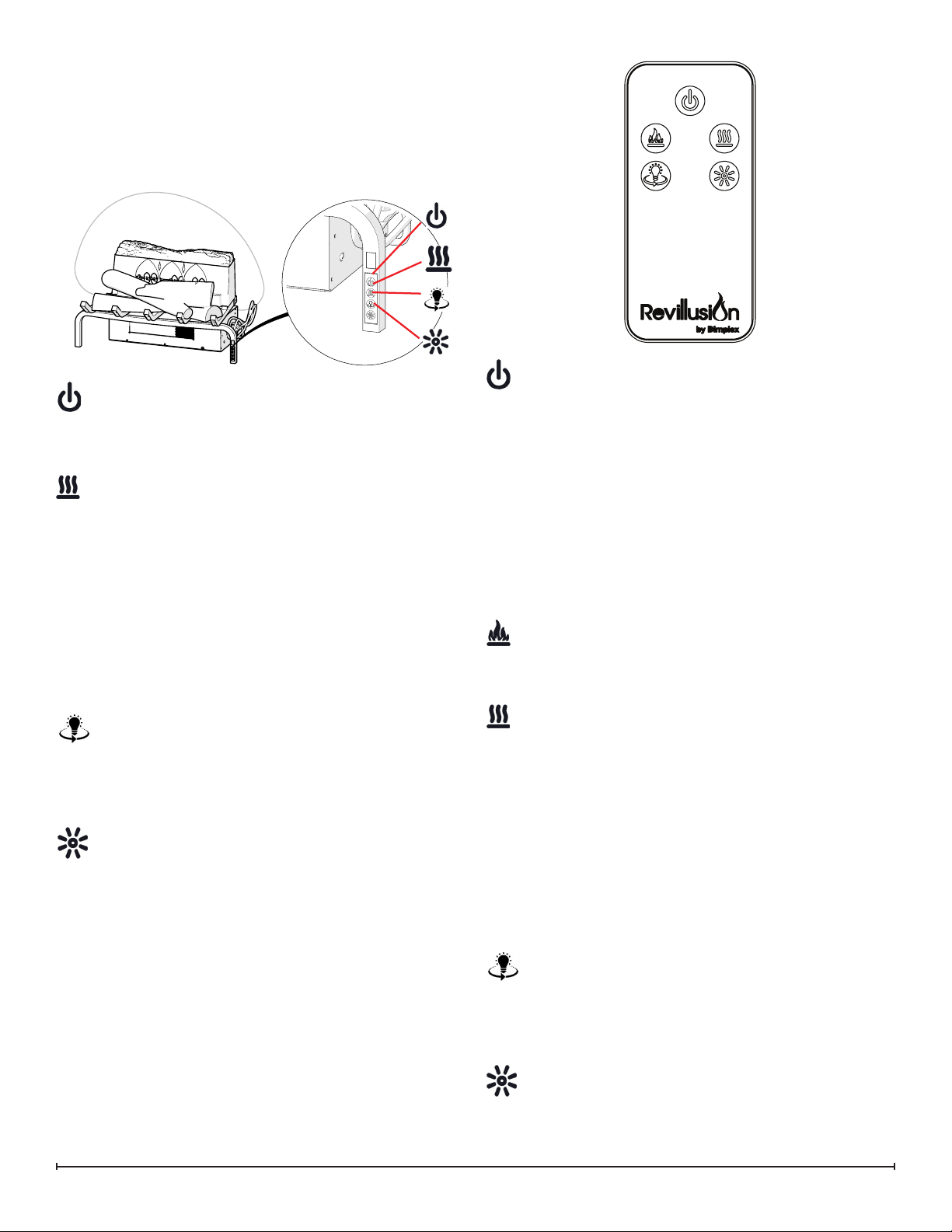
RLG20
Manual Control
The manual controls for the Revillusion are located on the
right-front leg of the log grate.
Power
Press to turn the ame effect on and activate the
previous heat setting (Off, Low, or High). Press again
to put the unit in standby mode.
Heat
• Heat On
Press to set the heat to Low (indicated by 1 short
beep). Press again to set the heat to High (indicated
by 2 short beeps).
• Heat Off
Press to turn heat Off (indicated by 1 long beep).
NOTE: After the heater is switched off, the fan will
!
continue on for 60 seconds before turning off. The
log LEDs remain On when the heater is ON and the
ame effect is Off.
360o Light
Press multiple times to change the LEDs on the
sides and back of the unit from white ickering to
white solid to Off. (This feature is active only when
the ame effect is On.)
Power
Press to activate the current standby state (On/Off).
•Standby State On
Press to turn everything Off. Press again to active the
previous ame effect state.
•Standby State Off
Press to activate the previous ame effect state.
- If the ame effect was On, the previous heat setting
will be activated (High, Low, or Off).
- If the ame effect was Off, the previous heat setting
will be activated (High or Low).
Press again to turn everything Off.
Flame
Press to light the back log, grate log, and ember mat
(optional), and start the ame effect.
Heat
• Heat On
Press to set the heat to Low (indicated by 1 short
beep). Press again to set the heat to High (indicated
by 2 short beeps).
• Heat Off
Brightness
Press multiple times to toggle the log set LEDs
through its four brightness settings.
Remote Control
The replace is supplied with a multi-function remote control.
The remote control has a range of approximately 30 ft (9
m). To operate correctly, the remote control must be pointed
toward the front of the unit.
Press to turn heat Off (indicated by 1 long beep).
NOTE: After the heater is switched off, the fan will
!
continue on for 60 seconds before turning off. The log
LEDs remain On when the heater is ON and the ame
effect is Off.
360o Light
Press multiple times to change the LEDs on the
sides and back of the unit from white ickering to
white solid to Off. (This feature is active only when
the ame effect is On.)
Brightness
Press multiple times to toggle the log set LEDs
3
Page 4
through its four brightness settings.
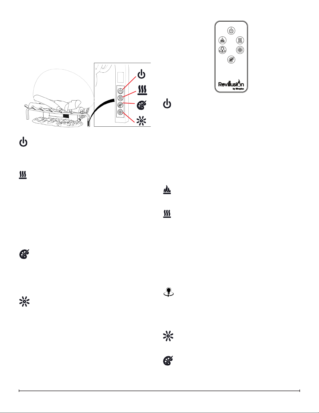
RLG25
Manual Control
The manual controls for the Revillusion are located on the
right-front leg of the log grate.
Power
Press to turn the ame effect on and activate the
previous heat setting (Off, Low, or High). Press again
to put the unit in standby mode.
Heat
• Heat On
Press to set the heat to Low (indicated by 1 short
beep). Press again to set the heat to High (indicated
by 2 short beeps).
• Heat Off
Press to turn heat Off (indicated by 1 long beep).
NOTE: After the heater is switched off, the fan will
!
continue on for 60 seconds before turning off. The
log LEDs remain On when the heater is ON and the
ame effect is Off.
Color Themes
Press multiple times to change the LED lights from:
ame base yellow, ame base blue, ame base
yellow with yellow 360 LEDs, ame base blue with
360 LEDs. (Feature is active only when the ame
effect is On.)
Brightness
Press multiple times to toggle the log set LEDs
through its four brightness settings.
Remote Control
Power
Press to activate the current standby state (On/Off).
•Standby State On
Press to turn everything Off. Press again to active the
previous ame effect state.
•Standby State Off
Press to activate the previous ame effect state.
- If the ame effect was On, the previous heat setting
will be activated (High, Low, or Off).
- If the ame effect was Off, the previous heat setting
will be activated (High or Low).
Press again to turn everything Off.
Flame
Press to light the back log, grate log, and ember mat,
and start the ame effect.
Heat
Heat On
Press to set the heat to Low (indicated by 1 short
beep). Press again to set the heat to High (indicated
by 2 short beeps).
• Heat Off
Press to turn heat Off (indicated by 1 long beep).
NOTE: After the heater is switched off, the fan will
!
continue on for 60 seconds before turning off. The
log LEDs remain On when the heater is ON and the
ame effect is Off.
360o Light
Press multiple times to change the LEDs on the
sides and back of the unit from natural yellow
ickering to yellow solid to white ickering to white
solid to Off. (Feature is active only when the ame
effect is On.)
The replace is supplied with a multi-function remote control.
The remote control has a range of approximately 30ft (9m).
To operate correctly, the remote control must be pointed
toward the front of the unit.
4 www.dimplex.com
Brightness
Press multiple times to toggle the log set LEDs
through its four brightness settings.
Color Themes
Press multiple times to change the ame base colors
from Yellow to Blue to Off. (Feature is active only
when the ame effect is On.)
Page 5
MAINTENANCE
General Maintenance
Inspect the log set regularly, depending upon conditions,
and at a minimum yearly intervals. Remove dust and clean
the logs, mat, grate, and base as required.
Except for installation and cleaning described in this manual, an authorized service representative should perform any
other servicing.
WARNING: Disconnect power and allow heater to cool
before attempting any maintenance or cleaning to reduce
the risk of fire, electric shock, or injury.
Clean Logs and Base
The log set should not be operated with an accumulation of
dust or dirt on or in the unit, as this can cause a build up of
heat and eventual damage.
Dust and vacuum the log set as needed. Use a damp cloth
and a mild detergent to clean painted surfaces of the fireplace. Never use abrasive cleaners.
Clean Mirage™ Flame Panel
The Mirage™ Flame Panel is cleaned in the factory during
the assembly operation. During shipment, installation, handling, etc., the screen may collect dust particles; these can
be removed by dusting lightly with a clean dry cloth.
To remove fingerprints or other marks, clean the Mirage™
Flame Panel reflector screen with a damp cloth. Never use
abrasive cleaners. Dry the screen completely with a lint free
cloth to prevent water spots.
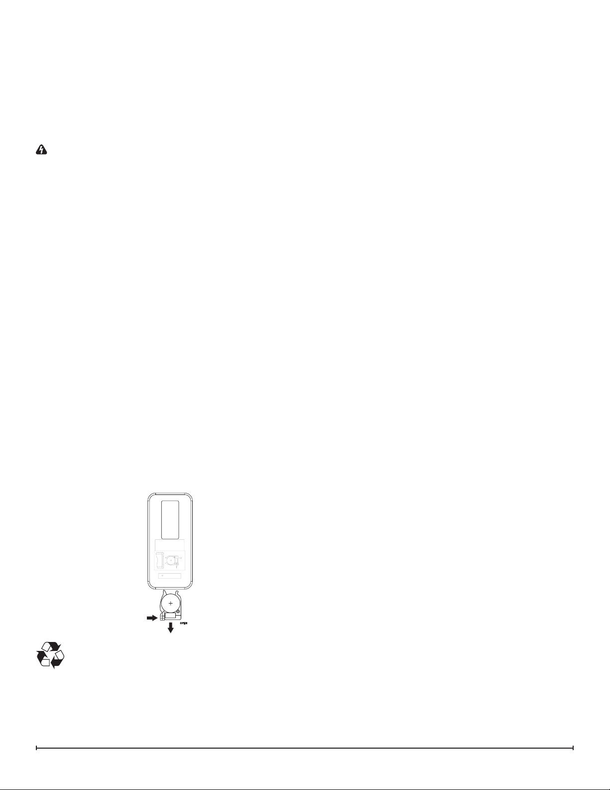
Battery Replacement
To replace the battery:
1. Push the release tab toward the center and slide the
battery cover open.
2. Install 3V Lithium battery in the battery holder. The
positive (+) side of the battery faces up.
3. Close the battery cover.
OPEN ---- OUVRIR
PUSH ---- POUSSER
RELEASE ---- DÉGAGER
Lithium Battery--Batterie au lithium
CR2025/2032
OPEN
RELEASE
PUSH
Battery must be recycled or disposed of properly.
Check with your Local Authority or Retailer for
recycling advice in your area.
5
Page 6

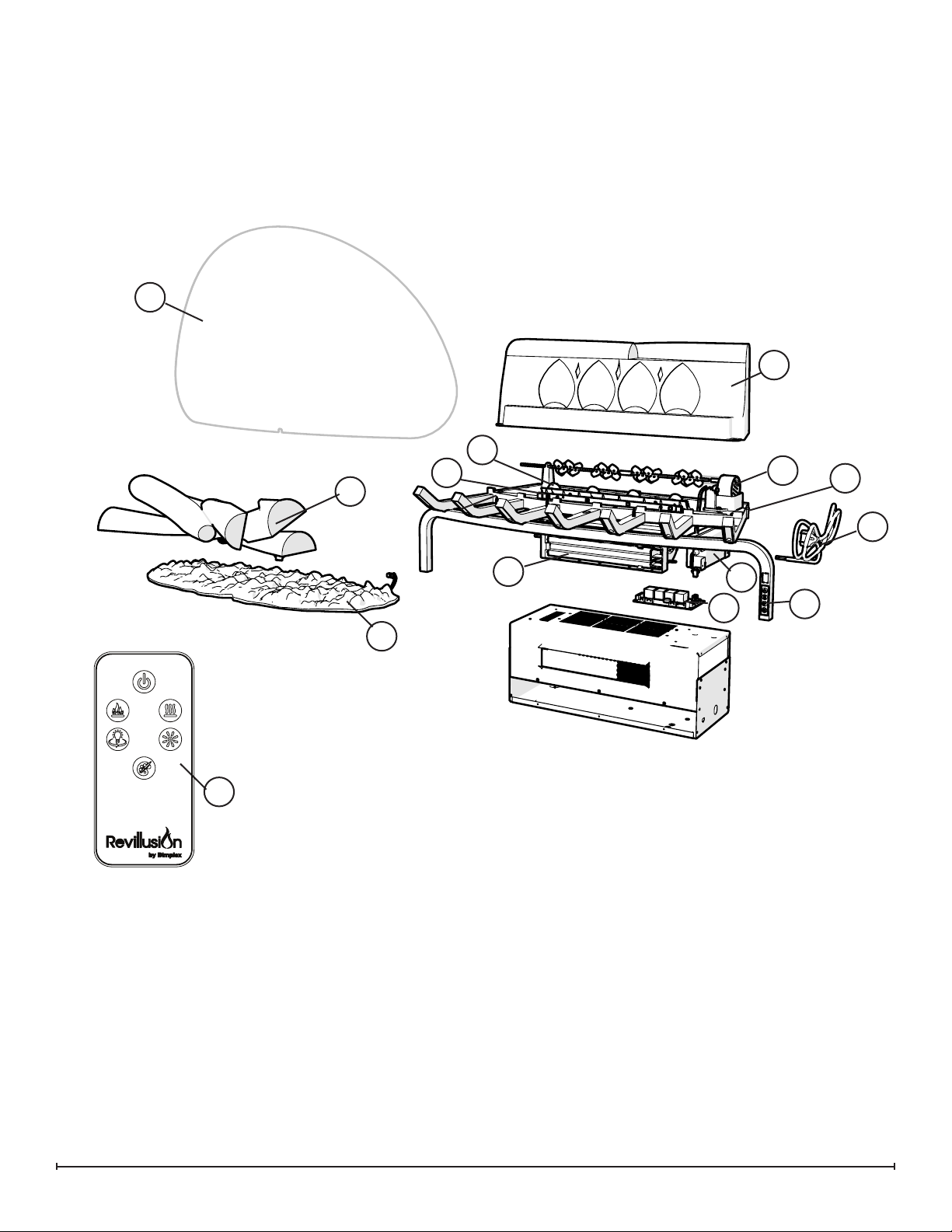
EXPLODED PARTS DIAGRAM - RLG20
4
3
6
2
5
1
12
REPLACEMENT PARTS LIST - RLG20
1. Logset, 20” . . . . . . . . . . . . . . . . . . . . . . . . . . . 0441910100RP
2. Flame LED Strip. . . . . . . . . . . . . . . . . . . . . . . 3001760100RP
3. Back Log ............................0441920100RP
4. Mirage™ Flame Panel ..................5902930100RP
5. Flicker Motor. . . . . . . . . . . . . . . . . . . . . . . . . . 2000500900RP
6. Back Light Assembly ...................3001770100RP
7. Heater-Blower Assy with Cutout. . . . . . . . . . . 2203730100RP
10
7
8
8. Main Control Board ....................3001740100RP
9. IR Key Board .........................3001750100RP
10. Power Supply . . . . . . . . . . . . . . . . . . . . . . . . . 2100250100RP
11. Cordset, 3-prong ......................4100190300RP
12. Remote Control .......................6700580100RP
Accessory
13. Ash Mat ..................................REM-KIT
9
11
6 www.dimplex.com
Page 7
EXPLODED PARTS DIAGRAM - RLG25
4
1
3
2
7
5
6
14
13
REPLACEMENT PARTS LIST - RLG25
1. Logset, 25” ...........................0441940100RP
2. Flame LEDs, 4x1W ....................3001760200RP
3. Back Log, 25” .........................0441950100RP
4. Mirage™ Flame Panel ..................5902880100RP
5. Flicker Motor, 18RPM, CCW .............2000500900RP
6. Back Light Assembly ...................3001780100RP
7. Coloured Light Assembly ................3001570400RP
12
8
8. Heater-Blower Assy with Cutout ...........2203730100RP
9. Main Control Board ....................3001740200RP
10. IR Key Board .........................3001750100RP
11. Power Supply .........................2100250100RP
12. Cordset, 3-prong ......................4100190300RP
13. Remote Control .......................6700580200RP
14. Ash Mat ..................................REM-KIT
11
9
10
7
Page 8
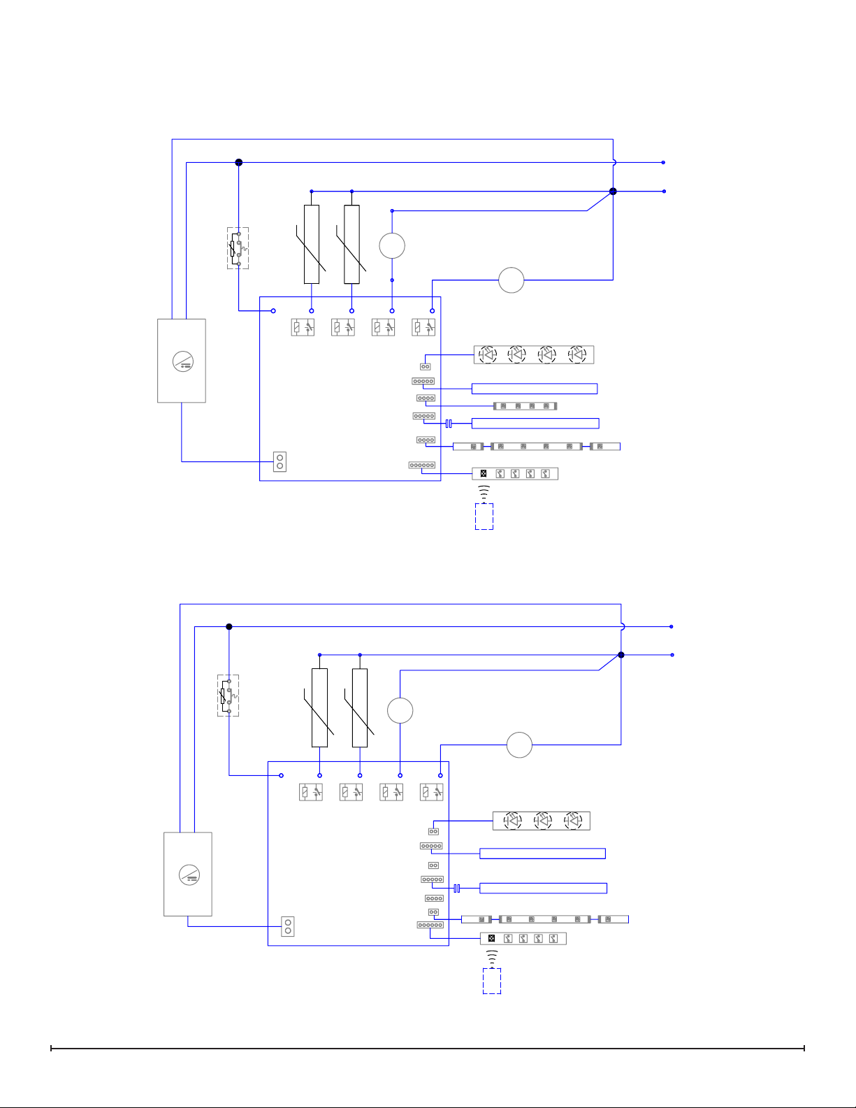
WIRING DIAGRAM
RLG25
CUTOUT
+T°
+T°
M
BLOWER
MOTOR
FLICKER
MOTOR
M
L
N
RLG20
120V / 12V
~
AC / DC
CUTOUT
CONTROL BOARD
+T°
+T°
M
BLOWER
MOTOR
REMOTE
FLAME LIGHTS
LOGSET ASSEMBLY
ASH MAT ASSEMBLY
360° COLOUR LIGHTS
FLICKER
MOTOR
M
4 x 1W LEDs
4-7 x 0.20mA LED STRIP
FLAME BASE COLOUR LIGHTS
4 PIECES
4 x 0.20mA RGB STRIP
4-7 x 0.20mA LED STRIP
2 PIECES
IR EYE/KEY BOARD
6 x 0.20mA RGB HARNESS
L
N
FLAME LIGHTS
3 x 1W LEDs
120V / 12V
LOGSET ASSEMBLY
4-7 x 0.20mA LED STRIP
4 PIECES
~
AC / DC
ASH MAT ASSEMBLY
360 LIGHTS
CONTROL BOARD
REMOTE
4-7 x 0.20mA LED STRIP
2 PIECES
IR EYE/KEY BOARD
6 x 0.20mA LEDs
8 www.dimplex.com
Page 9

BACK LOG REPLACEMENT
Tools Required: Philips head screwdriver
WARNING: If the log grate was operating prior to ser-
vicing, allow at least 10 minutes for the heating elements to
cool off to avoid accidental burning of skin.
WARNING: Disconnect power before attempting any
maintenance to reduce the risk of electric shock or damage
to persons.
RLG20
1. Lift the ame panel from the unit and put it aside in a
safe place.
2. Remove the ember mat by disconnecting it from the
right side of the unit (if applicable).
3. Remove the two screws at the front of the back log.
(Figure 3)
4. Install the replacement log and secure with the two
screws that were previously removed.
5. Reinstall the ame panel.
RLG25
1. Lift the ame panel from the unit and put it aside in a
safe place.
2. Remove the ember mat by disconnecting it from the
right side of the unit.
3. Remove the two screws at the front of the back log.
(Figure 3)
4. Remove the 3 screws along the bottom of the front and
back of the bottom assembly and the four screws from
each corner on both ends. (Figure 4)
5. Gently tilt the unit onto the back and lower the bottom
assembly so that the electrcial can be easily accessed.
6. Trace the wire from the back log to the main control
board and disconnect the wire, noting the location on
the board.
7. Run the wire from the new back log, following the same
path as the wire that was removed. Attach the new wire
to the board.
Figure 4
Bottom Assembly
Figure 5
Power Supply
Blower
Assembly
Main Control
Board
8. Install the replacement log and secure with the two
screws that were previously removed.
9. Re-assemble the remainder of the log grate in reverse
order from the instructions above.
WARNING: Ensure wires do not come in contact with
moving parts by securing wires in wiring tie wraps.
LOG SET REPLACEMENT
Tools Required: Philips head screwdriver
Figure 3
Back Log
WARNING: If the log grate was operating prior to servicing, allow at least 10 minutes for the heating elements to
cool off to avoid accidental burning of skin.
WARNING: Disconnect power before attempting any
maintenance to reduce the risk of electric shock or damage
to persons.
1. Lift the ame panel from the unit and put it aside in a
safe place.
2. Remove the ember mat by disconnecting it from the
right side of the unit.
3. Remove the 3 screws along the bottom of the front and
back of the bottom assembly and the four screws from
each corner on both ends. (Figure 4)
4. Gently tilt the unit onto the back and lower the bottom
assembly so that the electrcial can be easily accessed.
9
Page 10

5. Remove the two screws in the bottom of the second
and fourth prongs of the grate to release the logs.
6. Trace the wire from the logs to the main control board
and disconnect the wire, noting the location on the
board.
7. Run the wire from the new logs, following the same
path as the wire that was removed. Attach the new wire
to the board.
8. Install the replacement logs and secure with the two
screws that were previously removed.
9. Re-assemble the remainder of the log grate in reverse
order from the instructions above.
WARNING: Ensure wires do not come in contact with
moving parts by securing wires in wiring tie wraps.
FLAME LED STRIP AND COLOURED LED STRIP REPLACEMENT
Tools Required: Philips head screwdriver
WARNING: If the log grate was operating prior to ser-
vicing, allow at least 10 minutes for the heating elements to
cool off to avoid accidental burning of skin.
WARNING: Disconnect power before attempting any
maintenance to reduce the risk of electric shock or damage
to persons.
RLG20
1. Lift the ame panel from the unit and put it aside in a
safe place.
2. Remove the ember mat by disconnecting it from the
right side of the unit (if applicable).
3. Remove the two screws at the front of the back log.
(Figure 3)
4. Place the back log to the side, trying not to strain the
wires (if applicable).
Figure 6
5. Lift the LED strip out of the holder.
6. Gently pull the connector at the end of the strip out of
the plug.
7. Connect the new LED strip to the connector and reinstall.
8. Re-assemble the remainder of the log grate in reverse
order from the instructions above.
WARNING: Ensure wires do not come in contact with
moving parts by securing wires in wiring tie wraps.
BACK LIGHT ASSEMBLY REPLACEMENT
Tools Required: Philips head screwdriver
WARNING: If the log grate was operating prior to ser-
vicing, allow at least 10 minutes for the heating elements to
cool off to avoid accidental burning of skin.
WARNING: Disconnect power before attempting any
maintenance to reduce the risk of electric shock or damage
to persons.
RLG20
1. Lift the ame panel from the unit and put it aside in a
safe place.
2. Remove the ember mat by disconnecting it from the
right side of the unit (if applicable).
3. Locate the three sections of lights that are located
along the bottom edge of the grate. (Figure 6)
4. Depress each of the tabs and gently pull the light strips
forward and down to remove them from the unit.
5. Gently pull the connector at the end of the strip out of
the plug.
6. Connect the new LED strip to the connector and rein-
stall.
7. Re-assemble the remainder of the log grate in reverse
order from the instructions above.
WARNING: Ensure wires do not come in contact with
moving parts by securing wires in wiring tie wraps.
MAIN CONTROL BOARD REPLACEMENT
Flame LED
Strip
Back Light
Assembly
10 www.dimplex.com
Coloured LED Strip
(RLG25 only)
Tools Required: Philips head screwdriver
Needle-nose pliers
Flat Head Screwdriver
WARNING: If the log grate was operating prior to servicing, allow at least 10 minutes for the heating elements to
cool off to avoid accidental burning of skin.
WARNING: Disconnect power before attempting any
maintenance to reduce the risk of electric shock or damage
to persons.
1. Lift the ame panel from the unit and put it aside in a
safe place.
2. Remove the ember mat by disconnecting it from the
right side of the unit.
3. Remove the 3 screws along the bottom of the front and
back of the bottom assembly and the four screws from
Page 11
each corner on both ends. (Figure 4)
4. Gently tilt the unit onto the back and lower the bottom
assembly so that the electrcial can be easily accessed.
5. Transfer the wire connectors from the terminals on the
original board to the same location on the replacement
board.
!
NOTE: Use a at head screwdriver to gently pry
between the end of the connector and the remote control
receiver to release the wires.
6. Squeeze the mounting tabs located on the corners of
the board with the needle-nose pliers, to release the
tabs and lift the board off.
7. Position the new board over the tabs and gently press
down to engage the tabs.
8. Re-assemble the remainder of the log grate in reverse
order from the instructions above.
WARNING: Ensure wires do not come in contact with
moving parts by securing wires in wiring tie wraps.
POWER SUPPLY REPLACEMENT
Tools Required: Philips head screwdriver
WARNING: If the log grate was operating prior to ser-
vicing, allow at least 10 minutes for the heating elements to
cool off to avoid accidental burning of skin.
WARNING: Disconnect power before attempting any
maintenance to reduce the risk of electric shock or damage
to persons.
1. Lift the ame panel from the unit and put it aside in a
safe place.
2. Remove the ember mat by disconnecting it from the
right side of the unit.
3. Remove the 3 screws along the bottom of the front and
back of the bottom assembly and the four screws from
each corner on both ends. (Figure 4)
4. Gently tilt the unit onto the back and lower the bottom
assembly so that the electrcial can be easily accessed.
5. Remove the four remaining screws from the right end
pane to release the bracket that supports the power
supply.
Figure 7
6. Trace the wires to the main control board and the wire
nuts and replace the old connections with the new connections.
7. Reinstall the support bracket over the new power supply.
8. Re-assemble the remainder of the log grate in reverse
order from the instructions above.
WARNING: Ensure wires do not come in contact with
moving parts by securing wires in wiring tie wraps.
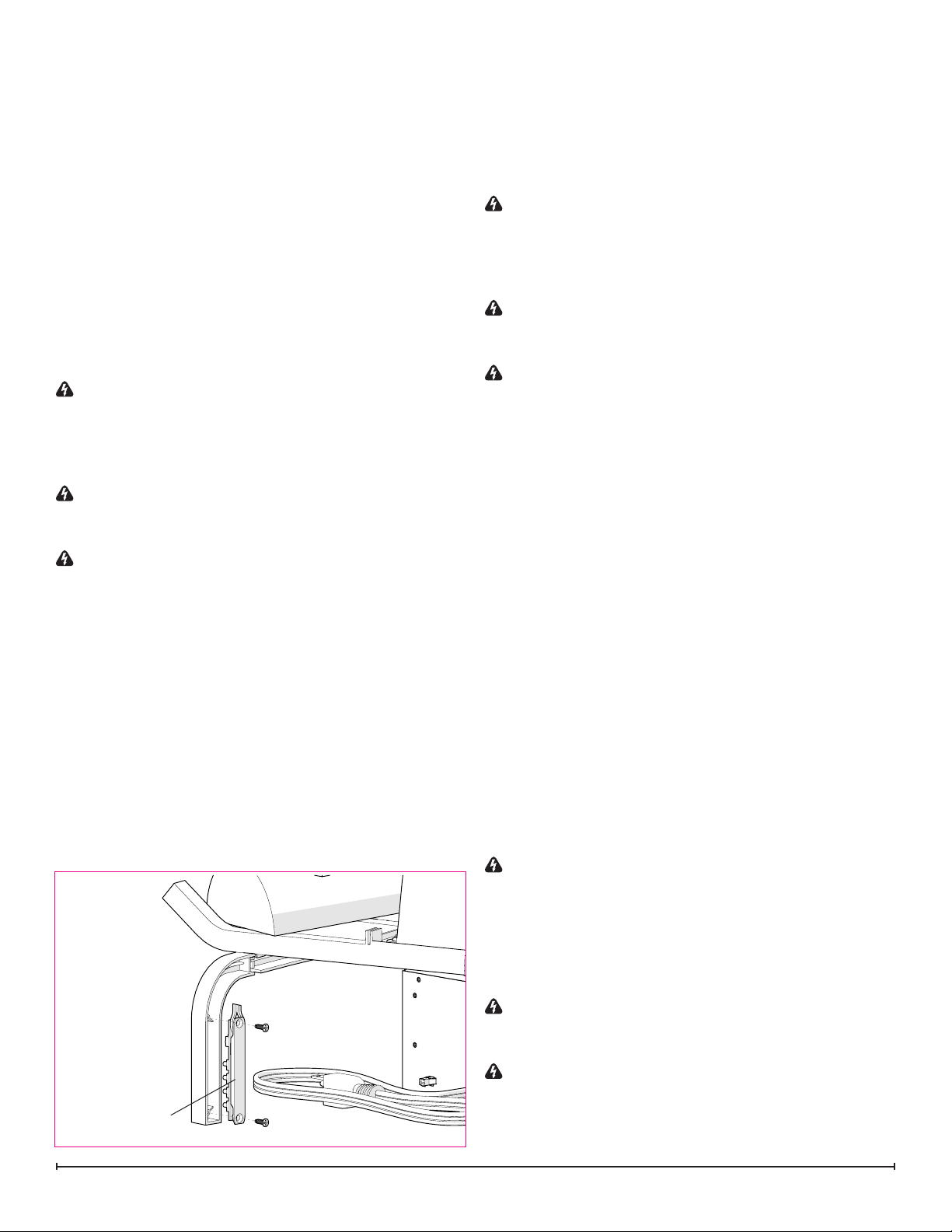
IR KEY BOARD REPLACEMENT
Tools Required: Philips head screwdriver
WARNING: If the log grate was operating prior to ser-
vicing, allow at least 10 minutes for the heating elements to
cool off to avoid accidental burning of skin.
WARNING: Disconnect power before attempting any
maintenance to reduce the risk of electric shock or damage
to persons.
1. Lift the ame panel from the unit and put it aside in a
safe place.
2. Remove the ember mat by disconnecting it from the
right side of the unit.
3. Remove the two screws securing the IR key board to
the back side of the right leg. (Figure 7)
4. Remove the 3 screws along the bottom of the front and
back of the bottom assembly and the four screws from
each corner on both ends. (Figure 4)
5. Gently tilt the unit onto the back and lower the bottom
assembly so that the electrcial can be easily accessed.
6. Trace the wire from the IR key board to the main con-
trol board and disconnect the wire, noting the location
on the board.
7. Run the wire from the IR key board, following the same
path as the wire that was removed. Attach the new wire
to the board.
8. Install the replacement key board and secure with the
two screws that were previously removed.
9. Re-assemble the remainder of the log grate in reverse
order from the instructions above.
WARNING: Ensure wires do not come in contact with
moving parts by securing wires in wiring tie wraps.
IR Key Board
POWER CORD REPLACEMENT
Tools Required: Philips head screwdriver
Needle-nose pliers
Flat Head Screwdriver
WARNING: If the log grate was operating prior to servicing, allow at least 10 minutes for the heating elements to
cool off to avoid accidental burning of skin.
WARNING: Disconnect power before attempting any
maintenance to reduce the risk of electric shock or damage
to persons.
1. Lift the ame panel from the unit and put it aside in a
11
Page 12

Figure 8
Flicker Rod
Flicker Motor
safe place.
2. Remove the ember mat by disconnecting it from the
right side of the unit.
3. Remove the 3 screws along the bottom of the front and
back of the bottom assembly and the four screws from
each corner on both ends. (Figure 4)
4. Gently tilt the unit onto the back and lower the bottom
assembly so that the electrcial can be easily accessed.
5. Follow the wiring from the power cord to the wire nuts,
removing any tie wraps and remove the connections,
taking note of the original locations.
6. Disconnect the ground wire from the screw on the bottom pane.
7. With needle nosed pliers, squeeze and push the grommet securing the power cord out of the casing.
8. Insert the new power cord and grommet, reattaching
the wire with new tie wraps.
9. Reconnect the wires according in their original conguration.
10. Re-assemble the remainder of the log grate in reverse
order from the instructions above.
FLICKER MOTOR REPLACEMENT
Tools Required: Philips head screwdriver
WARNING: If the log grate was operating prior to ser-
vicing, allow at least 10 minutes for the heating elements to
cool off to avoid accidental burning of skin.
WARNING: Disconnect power before attempting any
maintenance to reduce the risk of electric shock or damage
to persons.
RLG20
1. Lift the ame panel from the unit and put it aside in a
safe place.
2. Remove the ember mat by disconnecting it from the
right side of the unit (if applicable).
3. Remove the two screws at the front of the back log and
set it aside, ensuring that the wires are not strained (if
applicable). (Figure 3)
4. IRemove the 3 screws along the bottom of the front
and back of the bottom assembly and the four screws
from each corner on both ends. (Figure 4)
5. Gently tilt the unit onto the back and lower the bottom
assembly so that the electrcial can be easily accessed.
6. Remove the two screws that secure the motor support
to the base of the grate (verticle). (Figure 8)
7. Disconnect the icker rod and rubber grommet from the
icker motor.
8. Remove the two screws that secure the motor from the
motor support (horizontal). (Figure 8)
9. Trace the wires from the motor to the main control
board and disconnect the wire, noting the location on
the board.
10. Run the wire from the new motor, following the same
path as the wire that was removed. Attach the new wire
to the board.
11. Re-assemble the remainder of the log grate in reverse
order from the instructions above.
WARNING: Ensure wires do not come in contact with
moving parts by securing wires in wiring tie wraps.
HEATER ASSEMBLY REPLACEMENT
Tools Required: Philips head screwdriver
Flat Head Screwdriver
WARNING: If the log grate was operating prior to servicing, allow at least 10 minutes for the heating elements to
cool off to avoid accidental burning of skin.
WARNING: Disconnect power before attempting any
maintenance to reduce the risk of electric shock or damage
to persons.
1. Lift the ame panel from the unit and put it aside in a
safe place.
2. Remove the ember mat by disconnecting it from the
right side of the unit.
3. Remove the 3 screws along the bottom of the front and
back of the bottom assembly and the four screws from
each corner on both ends. (Figure 4)
4. Gently tilt the unit onto the back and lower the bottom
assembly so that the electrcial can be easily accessed.
5. Remove the four screws in the top assembly - two on
either end of the heater.
6. Turn the logs and log grate on its side, to the right, to
access the four screws that secure the heater assembly to the top assembly.
7. On the heater assembly, there is a plastic spacer that
channels the air from the heater assembly out of the
unit, remove the two screws on either end that hold the
plastic spacer to the heater.
8. Install the plastic spacer to the new heater, transfer the
wires from the old heater to the new heater and re-assemble the remainder of the log grate in reverse order
from the instructions above.
12 www.dimplex.com
Page 13

Figure 9
Connecting
Screws
Plastic
Spacer
!
NOTE: Use a at head screwdriver to gently pry be-
tween the end of the connector and the heater assembly to
release the wires.
WARNING: Ensure wires do not come in contact with
moving parts by securing wires in wiring tie wraps.
13
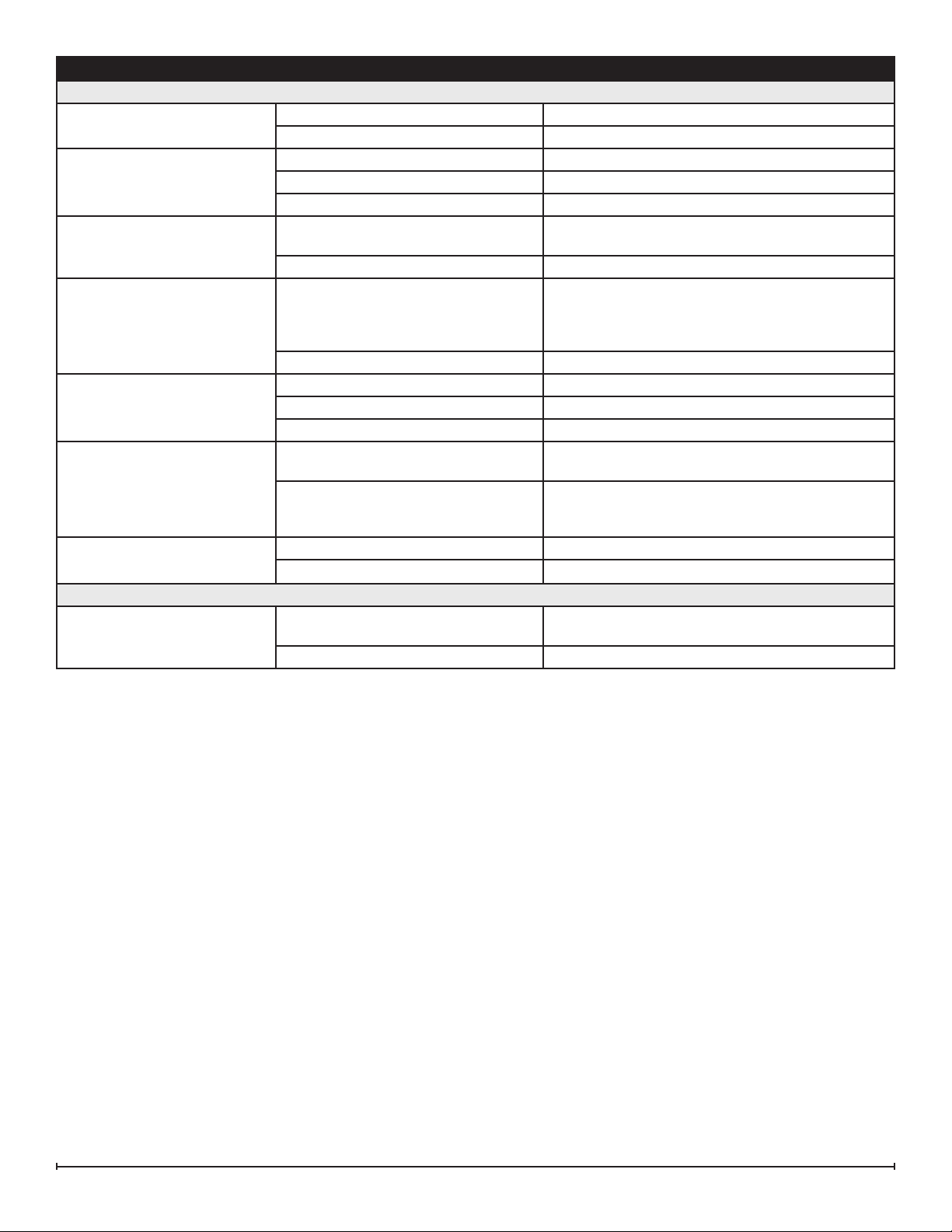
Page 14

TROUBLESHOOTING GUIDE
PROBLEM CAUSE SOLUTION
General
Circuit breaker trips or fuse
blows when unit is turned on
Lights dim in room while the unit
is on
Power cord gets warm Normal Operation The power cord may get slightly warm to the touch
Appearance
Log grate does not turn on in
Manual Mode
Log grate does not turn on in
Remote Mode
One or all logs in log set dim, not
glowing
Back log dim, not glowing
(only applicable for the RLG25)
Flame dim or not appearing Improper operation Refer to Operation Section
Flame Frozen Loose wiring Check wiring connections
Flame Shudder Defective Flicker Motor Replace Flicker Motor
Back lighting dim or not
appearing
Colour themes dim or not appearing
Short in unit wiring. Trace wiring in unit.
Improper circuit current rating Additional appliances may exceed the current rating
of the circuit breaker or fuse. Plug unit into another
outlet or install unit on a dedicated 15 amp circuit.
Unit is drawing close to circuit current
rating
Defective power cord Replace power cord if cord gets hot to the touch.
Improper operation Refer to cperation section
No incoming power from the electrical
wall socket
Defective IR key board Replace IR key board
Defective main control board Replace main control board.
Improper operation Refer to Operation Section
Loose wiring Check wiring connections
Remote Control not working Install new battery into the Remote Control. Reinitial-
Defective main control board Replace main control board.
Loose connection Check wiring connections
Defective log set wiring Replace log set assembly
Loose connection Check wiring connections
Defective back log wiring Replace back log assembly
Loose connection of ame LEDs Check wiring connections
Defective ame LED wiring Replace ame LED assembly
Defective main control board Replace main control board.
Defective Flicker Motor Replace Flicker Motor
Improper operation Refer to Operation Section
Loose connection of back light LEDs Check wiring connections
Defective back light LED wiring Replace back light LED assembly
Defective main control board Replace main control board.
Improper operation Refer to Operation Section
Loose connection of coloured LEDs Check wiring connections
Defective coloured LED wiring Replace coloured LED assembly
Defective main control board Replace main control board.
Move the unit to another outlet or install unit on a dedicated 15 amp circuit
when the heater is on
Check fuse/breaker panel
ize remote control where necessary
14 www.dimplex.com
Page 15
PROBLEM CAUSE SOLUTION
Heater
Heater is not turning Off Improper operation Refer to Operation Section
Defective main control board Replace main control board.
Heater is not turning On Improper operation Refer to Operation Section
Loose wiring Check wiring connections
Defective heater assembly Replace heater assembly
Heater is turning off after a
couple of minutes of operation
Heater emits an odor Normal Operation Normal operation is when the heater emits an odor
Heater fan turns on but heater
lacks heat
Heating element is glowing red Normal Operation Small glowing sections of the element are considered
Heater fan runs continuously Loose wiring Trace wiring in unit
Noise
Excessive noise with the heater onDirty heater assembly Ensure that exterior intake louvers and log grate cavity
Build up of dirt/dust in heater assembly Ensure that exterior intake louvers and log grate cavity
are free of dirt/dust.
Defective Heater Assembly Replace Heater Assembly
for a brief period after the heater is initially turned on.
The heater is burning off any dust accumulated during
manufacturing or operation.
Defective heater assembly Replace heater assembly
Improper operation Refer to Operation Section
Loose wiring Trace wiring in unit
Defective heater assembly Replace heater assembly
normal.
Defective heater assembly If larger glowing sections are causing the heater to trip
the thermal cutout, unplug unit, discontinue use and
replace heater assembly.
Defective heater assembly Replace heater assembly
are free of dirt/dust.
Defective heater assembly Replace heater assembly
15
 Loading...