

Page 1
Kickspace Heater
3 5/8"
22 3/8"
CABLE
SERVICE
KNOCKOUTS
3 1/2"
9 1/2"
22"
10" MIN.
CKHA/RKHA Series
IMPORTANT INSTRUCTIONS
Please carefully read and save these instructions
When using electrical appliances, basic precautions should
always be followed to reduce the risk of re, electric shock
and injury to person, including the following:
Read all instructions before using this heater.1.
A heater has hot and arcing or sparking parts inside. Do 2.
not use it in areas where gasoline, paint or ammable
liquids are used or stored.
This heater is hot when in use. To avoid burns, do not let 3.
bare skin touch hot surfaces. If provided, use handles
when moving this heater. Keep combustible materials
such as: furniture, pillows, bedding, papers, clothes and
curtains away from heater.
To prevent a possible re, do not block air intakes or 4.
exhaust in any manner. Do not use on soft surfaces like
a bed where openings may become blocked.
Do not insert or allow foreign objects to enter any venti-5.
lation or exhaust opening as this may cause an electric
shock or re, or damage the heater.
SAVE THESE INSTRUCTIONS
Measure area of intended use. If there is not sufcient 1.
room for the grille frame, the frame may be removed by
removing grille frame from heater (screw “A”), remove
frame and re-insert grille.
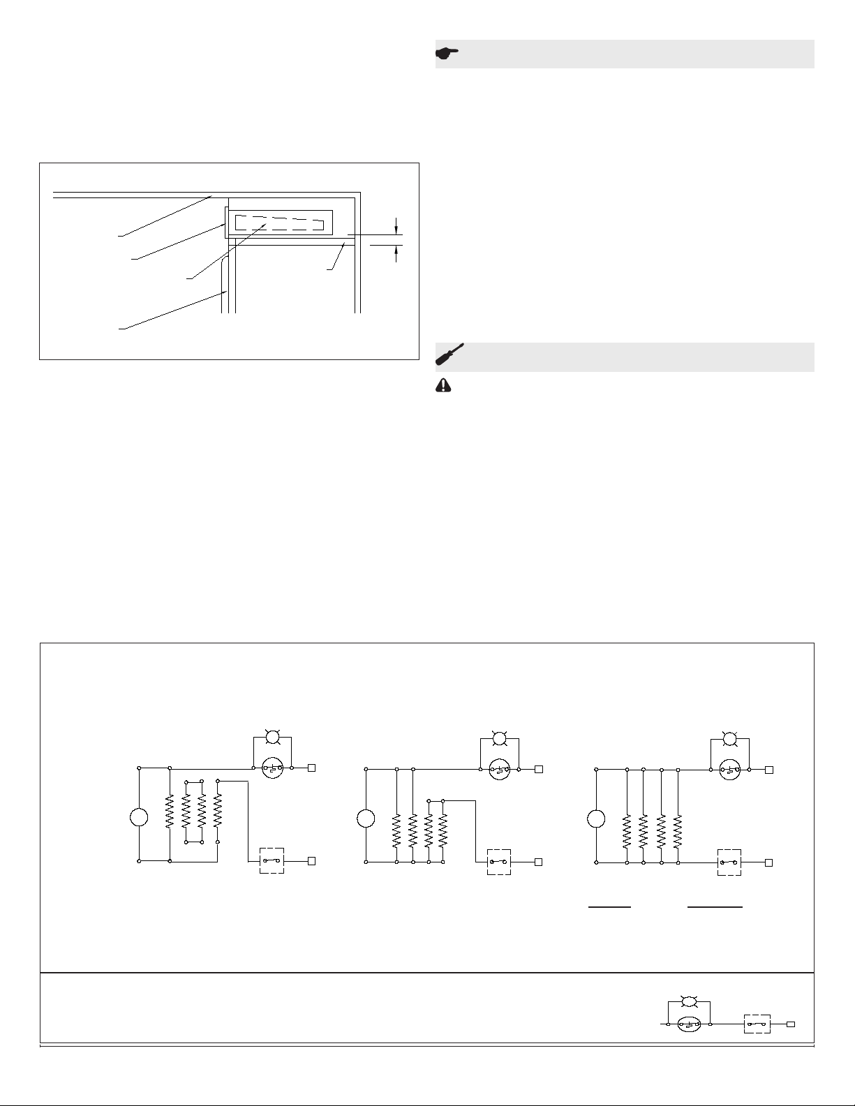
Cut 22 3/8” x 3 5/8” opening (Figure 2). Keep clearance 2.
area free of obstructions.
Bring in service cable to left or rear of 10” minimum area 3.
as shown in Fig.2.
Remove heater cover and appropriate knockout. Attach 4.
service cable to unit with approved connector and connect colour to colour in outlet box. To change wattage or
voltage connections, see Figure 4.
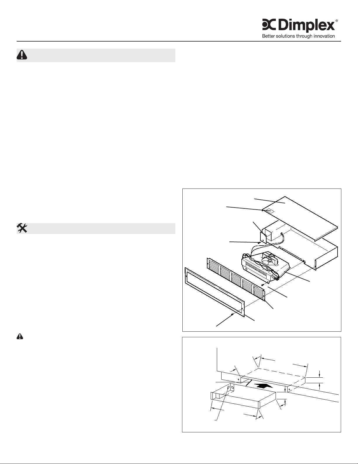
Replace cover, slide unit into opening, and secure each 5.
side (Figure 1).
!
NOTE: Make sure unit is installed right side up. Re- Make sure unit is installed right side up. Re-
fer to “TOP” label.
For inspection of eld wiring, see instruction under “Electrical
Inspection”.
FIGURE 1
Top Label
Heater Cover
Junction Box Cover
Installation Instructions
Congratulations on purchasing a kickspace heater from
Dimplex North America. Your heater is manufactured using
the highest quality materials and workmanship and will
provide many years of trouble free service.
!
NOTE: It is extremely important to read all information
labels. Care must be taken to ensure that the heater is
rated the same voltage as the electrical supply wires.
Failure to do so could result in unsafe heater operation as
well as damage to the unit. If replacing an existing heater,
check the labels of the old heater to ensure the voltage of
the new heater is compatible.
!
NOTE: Care must be taken to prevent undue strain on all
wiring or heating element assembly, when removing and
re-assembling heating element assembly.
CAUTION: For eld rewiring to 120V all leads must be
secured under wire clamps.
!
NOTE: Air and grille temperatures conform to CSA & UL
regulations but may discolour certain materials, particularly those materials incorporating clear vinyl. Materials
should be checked prior to installation to determine if
discolouration or distortion would occur in the vicinity of
60°C (140° F)
Kickspace Installation
!
NOTE: Unit should be installed so that it is not directly
under sink or other frequently used work area as air temperature may be uncomfortably warm. Also, if carpeting is on
oor, mount unit so bottom of grille is level or above the top
of the carpet pile.
Screw ‘A’
FIGURE 2
Screw ‘C’
Heater
Element
Screw‘B’
Grille
Trim Frame
7200960100R06
Page 2
SoftorStairRiserInstallation
MIN.
3/4
ADDED SUPPORT
PARTITION OR
DOOR
HEATER
GRILLE
CEILING
CABINET
Cut opening as for kickspace installation (22 3/8” x 3 1.
5/8”). Allow 3/4” clearance above cabinet doors. Add
supports for unit (Figure 3).
Proceed as for kickspace installation. After securing unit 2.
in opening, install combination of frame and grille (Figure
1).
FIGURE 3
Operation
This heater must be properly installed before it is used.1.
Prior to energization remove all construction dirt (plaster, 2.
sawdust, etc.) from interior and exterior of heater.
Adjust thermostat with screwdriver. This unit is also 3.
controllable from a line voltage wall thermostat or eld
installed built-in tamperproof single or double pole
thermostat kit.
Dimplex kickspace heaters are designed and tested for safe
and trouble-free operation. All Dimplex kickspace heaters
are protected against overheating by a built-in thermal cutout.
Free airow throughout the heater is extremely important for
the most efcient operation of the heater. Restricted airow
may cause the thermal overload protector to cycle the heater
“ON and OFF”. A cycling heater will not supply sufcient heat
to the room.
Avoid direct contact of paper, fabric, or furniture with heater.
Maintenance
CAUTION: Disconnect all power coming to heater at
main service panel before wiring or servicing.
SERVICING - Remove grille and frame by removing screws
“A”. Remove two screws “B”, and slide out heating assembly. When re-assembling, reverse the procedure above.
Cleaning
With grille in place• - Use vacuum cleaner hose to suck
out lint and dirt around grille. Reverse hose on vacuum
to use as a blower to move dust out of enclosure. Re-
verse hose back to suck out dirt at front area of heater.
With grille removed• - Remove two screws “B” at bottom
front of heating element assembly. Pull gently to remove
it from enclosure. Swing assembly out. Vacuum inside
of enclosure and around heating element assembly. Reverse procedure above to re-assemble unit.
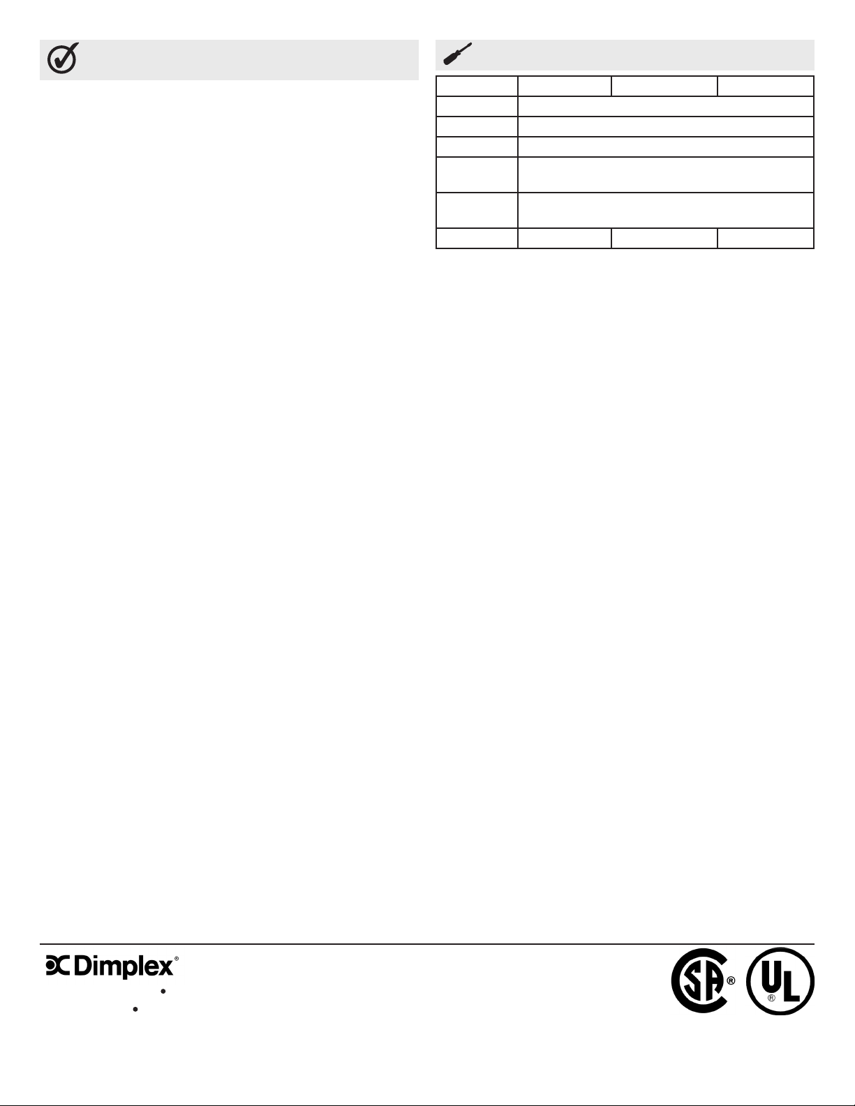
Figure 4
FACTORY CONNECTION
208/240 VOLT 675/900 WATTS
3.2 A / 3.7A
M
FAN
IMPORTANT: RETIGHTEN ALL LEADS WITH CABLE CLAMP AFTER RECONNECTING
UNINSULATED ENDS OF UNUSED LEADS WITH WIRE NUTS
NOTE: If installing unit with factory thermostat, see supplemental wiring diagram, Fig. 4a.
FACTORY CONNECTION
208/240 VOLT 1350/1800 WATTS
6.5 A / 7.5 A
FAN
SAFETY SWITCH SAFETY SWITCHSAFETY SWITCH
FACTORY CONNECTION
120 VOLT
MM
FAN
RATING CONNECT
450W/ 3.75A 7-8 (AS SHOWN)
900W/ 7.5A 7-8, 1-2
1350W/ 11.2A 7-8, 1-2, 3-4
1800W/ 15A 7-8, 1-2, 3-4, 5-6
Figure 4a
THERMOSTAT
www.dimplex.com2
Page 3
Warranty
The Manufacturer warrants the heating elements and
components of the enclosed product against any defect in
material or workmanship for a period of one year from the
date of purchase. In full satisfaction of any claims under
this Warranty the Manufacturer will repair or replace without
charge, in its factory or in the eld as it alone may decide,
any parts which in its opinion are defective.
The Manufacturer shall not be responsible for any
transportation or shipping costs in relation to such repair
or replacement except as specically assumed by it.
Misuse of this product or repairs by persons other than
the Manufacturer’s authorized personnel without the
Manufacturer’s written approval, will void this Warranty.
This Warranty is in lieu of all other warranties or conditions
whether expressed or implied including but not limited to
those of merchantability or tness for purpose and shall
constitute the sole remedy of the Purchaser and the sole
liability of the Manufacturer in respect of the sale of the
product, whether in the nature of breach or breach of
fundamental term, or of negligence or otherwise.
The Manufacturer shall not be liable for any special, indirect
or consequential damages or for any damages resulting from
removal or replacement of a heater subject to warranty claim
without the Manufacturer’s authorization.
Replacement Parts
CKHA20D31 CKHA20D31W RKHA20D31W
Motor 2000280400RP
Fan Blade 5300210100RP
Element 2203260100RP
Cut Out
(Manual)
Cut Out
(Automatic)
Grill Kit CKHABG CKHAWG CKHAWG
03005035RP
211A619RP
This Warranty is transferable by the original consumer
purchaser of the product. Any claims under this Warranty
must be submitted in writing to the Service Manager, Dimplex
North America Ltd., 1367 Industrial Rd., Cambridge, Ontario
N1R 7G8, Canada.
1367 Industrial Road Cambridge ON Canada N1R 7G8
1-888-346-7539 www.dimplex.com
In keeping with our policy of continuous product improvement, we reserve the right to make changes without notice.
© 2011 Dimplex North America Limited
3
Page 4

3 5/8"
22 3/8"
CABLE
SERVICE
KNOCKOUTS
3 1/2"
9 1/2"
22"
10" MIN.
Plinthe Coup de pied
Série CKHA/RKHA
InstructIons ImportantEs
Lorsque vous utilisez un appareil électrique, il est important de
toujours prendre des mesures de sécurité de base pour réduire
les risques d’incendie, de chocs électriques ou de blessures :
Lire toutes les instructions avant d’utiliser cet appareil1. .
Tous les appareils chauffants électriques contiennent des 2.
pièces qui chauffent et qui peuvent produire un arc électrique ou des étincelles. Ne pas faire fonctionner dans des
endroits où de l’essence, de la peinture et autres produits
inammables sont utilisés ou rangés.
L’appareil devient chaud lorsqu’il est en marche. Pour 3.
éviter les brûlures, ne pas toucher les surfaces chaudes. Si,
utiliser les poignées pour déplacer cet appareil de chauffage. Garder éloigné du devant de l’appareil tout matériel
combustible, tels que meubles, oreillers, literie, papier, vêtements et rideaux.
Pour éviter les incendie, ne pas obstruer l’entrée ou la 4.
sortie d’air d’aucune façon. Ne pas utiliser l’appareil sur des
surfaces instables, comme un lit, où les ouvertures risquent
de se bloquer.
Ne pas introduire d’objets étrangers dans la prise d’air de 5.
ventilation ou la bouche de sortie d’air, car cela peut occasionner des chocs électriques, provoquer un incendie ou
endommager les éléments chauffants.
peut être extrêmement chaud. De plus, si le plancher est
recouvert de tapis, xez l’appareil de manière à ce que le
bas de la grille soit égal au velours du tapis ou plus haut.
Mesurez l’endroit où vous voulez installer le radiateur. S’il 1.
n’y a pas assez d’espace pour le cadre de la grille, retirez la
grille du radiateur (vis A), retirez le cadre et remettez la grille
en place.
Coupez une ouverture de 22 3/8 po x 3 5/8 po. Gardez la 2.
zone à dégager libre de tout obstacle.
Amenez le câble de branchement à gauche, à l’arrière de la 3.
zone minimale de 10 po, tel qu’illustré à la Figure 2.
Retirez le couvercle du radiateur et la rondelle défonçable 4.
appropriée. Fixez le câble de branchement à l’appareil à
l’aide du connecteur homologué et branchez les ls de
couleur dans la boîte de sortie. Pour modier les connexions de tension ou de puissance, reportez-vous à la Figure
4.
Remettez le couvercle en place, glissez l’appareil dans 5.
l’ouverture et xez-le de chaque côté (Figure 1).
FIGURE 1
Couvercle de
L’element Chauffant
Etiquette
Superieure
Couvercle de la Boite
de Raccordement
consErVEr cEs InstructIons
Instructions D’ Installation
Félicitations pour votre achat d’un plinthe coup de pied de
Dimplex Amérique du Nord Ltée. Le produit est conçu à l’aide de
matériaux et de techniques de fabrication de qualité supérieure
assurant de nombreuses années d’utilisation sans défaillance.
!
NOTA : Il est extrêmement important de lire les étiquettes.
Veillez à ce que la capacité en voltage du radiateur
corresponde à celle de l’équipement électrique. Dans le cas
contraire, l’utilisation du radiateur pourrait comporter des
risques pour la sécurité et endommager l’appareil. Dans le
cas d’un remplacement de radiateur existant, veillez à ce
que la capacité en voltage du radiateur neuf soit compatible
aux spécications indiquées sur les étiquettes apposées sur
l’appareil en place.
!
NOTA: Faites attention de ne pas déformer accidentellement
les câbles ou l’élément chauffant lorsque vous les retirez et
les remettez en place.
MISE EN GARDE: Pour la pose de câbles de 120 V, tous les
ls doivent être protégés par des attache-câbles.
!
NOTA: La température de l’air et de la grille est conforme
aux normes CSA et UL mais peut causer la décoloration
de certains matériaux, particulièrement s’ils contiennent du
vinyle transparent. Avant l’installation, vériez les matériaux
pour vous assurer qu’ils ne se décoloreront pas ou ne se
déformeront pas à une chaleur d’environ 60o C (140o F).
Installation en retrait
!
NOTA: N’installez pas l’appareil directement sous un
évier ou une zone de travail fréquemment utilisée car l’air
Vis ‘A’
FIGURE 2
Cables de
Branchement
Rondelle
defoncable
Vis ‘C’
Element
Chauffant
Vis‘B’
Grille
Cadre de Retrait
7200960100R01
Page 5

MIN.
3/4
ADDED SUPPORT
PARTITION OR
DOOR
HEATER
GRILLE
CEILING
CABINET
!
NOTA: Assurez-vous que l’appareil est installé du bon
côté en vous référant à l’étiquette « TOP ».
Pour l’inspection de la pose des câbles, consultez les in-6.
structions de la section « Inspection électrique ».
Installation sur une sous-face ou une contremarche
Coupez une ouverture (22 3/8 po x 3 5/8 po), comme pour 1.
l’installation en retrait. Laissez un dégagement de 3/4 po
au-dessus des portes d’armoire. Ajoutez des supports pour
l’appareil (Figure 3).
Effectuez l’installation de la même façon que pour 2.
l’installation en retrait. Une fois l’appareil xé dans
l’ouverture, installez le cadre et la grille (Figure 1).
tionnement sans problèmes. Tous les radiateurs Dimplex sont
munis d’un coupe-circuit thermique intégré an de prévenir les
surchauffes. Il est très important que l’air circule librement à
travers le radiateur pour assurer son fonctionnement optimal.
Lorsque la circulation d’air est entravée, le dispositif de protec-
tion de surcharge thermique peut entraîner l’arrêt et la mise en
marche cycliques du radiateur. Un radiateur qui fonctionne de
façon cyclique ne pourra réchauffer la pièce de façon adéquate.
Évitez tout contact direct entre le radiateur et le papier, le tissu
ou les meubles.
Entretien
FIGURE 3
Plafond
Grille
Element
Chauffant
Porte
Cloison ou
soutien
supplementaire
D’armoire
Utilisation
Cet appareil doit être installé correctement avant de l’utiliser.1.
Avant la mise en marche, enlevez toute la poussière liée à la 2.
construction de l’intérieur et de l’extérieur du radiateur (plâtre,
sciure, etc.).
Adjustez le thermostat a l’aide d’un tournevis. L’appareil est 3.
contrôlé par un thermostat électrique mural ou un thermostat
unipolaire ou bipolaire anti-vandale intégré installé par le
client.
Les radiateurs Dimplex ont été conçus et testés pour un fonc-
Figure 4
BRANCHEMENT A L’USINE
208/240 VOLT 675/900 WATTS
3.2 A / 3.7A
BRANCHEMENT SUR PLACE
208/240 VOLT 1350/1800 WATTS
6.5 A / 7.5 A
MISE EN GARDE : Avant de retirer le couverture pour le
nettoyage, s’assurer que le pouvoir a été coupé au panneau
électrique.
ENTRETIEN – Retirez la grille et le cadre en enlevant les vis « A
». Retirez les deux vis « B » et sortez l’élément chauffant. Pour
réassembler, faites l’inverse.
Nettoyage
Si la grille est en place – À l’aide d’un aspirateur, enlevez •
la mousse et la saleté autour de la grille. Inversez le tuyau
de l’aspirateur pour l’utiliser comme soufeur et enlevez la
poussière de l’appareil. Remettez le tuyau en position aspirateur et aspirez la poussière à l’avant du radiateur.
Si la grille est retirée – Retirez les deux vis « B » en bas, •
devant l’élément chauffant. Tirez doucement pour le sortir et
mettez-le de côté. Nettoyez l’intérieur du radiateur et autour
de l’élément chauffant. Inversez la marche à suivre ci-dessus pour réassembler l’appareil.
BRANCHEMENT SUR PLACE
120 VOLT
FAN
M
COMMANDE DE
SÉCURITÉ
IMPORTANT: RESSERREZ TOUS LES CABLES A L’AIDE D’ATTACHE-CABLES APRESLE
BRANCHEMENT DES EXTREMITES NON ISOLEES DES CABLES NON UTILISES AU MOYEN DE
CAPUCHONS DE CONNEXION
NOTA: Si vous installez l’appareil avec le thermostat de l’usine, consultez
le diagramme de cablage supplementaire. Fig. 4a.
FAN
COMMANDE DE
SÉCURITÉ
FAN
Figure 4a
MM
COMMANDE DE
SÉCURITÉ
ESTIMATION COMMUNIQUER
450W/ 3.75A 7-8 (AS SHOWN)
900W/ 7.5A 7-8, 1-2
1350W/ 11.2A 7-8, 1-2, 3-4
1800W/ 15A 7-8, 1-2, 3-4, 5-6
THERMOSTAT
www.dimplex.com2
Page 6

Garantie
Le fabricant garantit les éléments et composantes chauffants du
produit contre toute défectuosité de matériel ou de fabrication pour
une période de deux année de la date d’achat. An de répondre
à toute réclamation en vertu de la présente garantie, le fabricant
réparera en usine ou sur les lieux ou remplacera sans frais, toute
pièce défectueuse qu’il juge approprié.
Le fabricant n’est pas responsable des frais de transport ou de
livraison relatifs à de tels remplacements ou réparations à moins
qu’il ne s’en porte garant. La garantie sera nulle si les dommages
sont causés par une mauvaise utilisation du produit ou si des réparations sont effectuées par des personnes autres que le fabricant,
sans autorisation écrite.
Cette garantie est en lieu et place de toutes les autres garanties ou
conditions, expresses ou implicites, incluant, entre autres, celles
relatives à la qualité marchande ou à la conformité aux besoins et
constitue le seul recours de l’acheteur et l’unique responsabilité du
fabricant afférente à la vente du produit, qu’il s’agisse de la non-
observance d’une modalité fondamentale, de la nature de cette
inobservance, de négligence ou autre.
Le fabricant n’est pas tenu responsable de tout dommage spécial,
indirect ou consécutif, ou de tout dommage résultant du retrait ou
du remplacement d’un radiateur sous garantie sans l’autorisation
du fabricant.
La présente garantie peut être transférée par l’acheteur d’origine
du produit. Toute réclamation en vertu de la présente garantie
doit être soumise par écrit au chef du service d’entretien, Dimplex
North America Ltd., 1367 Industrial Rd., Cambridge, Ontario N1R
7G8, Canada.
Pièce de Rechange
CKHA20D31 CKHA20D31W RKHA20D31W
Moteur 2000280400RP
Ventilateur 5300210100RP
Élément 2203260100RP
Coupe-Circuit
(Manuel)
Coupe-Circuit
(Automatic)
Kit de Gril CKHABG CKHAWG CKHAWG
03005035RP
211A619RP
1367 Industrial Road Cambridge ON Canada N1R 7G8
1-888-346-7539 www.dimplex.com
Conformément à notre politique visant à améliorer sans cesse nos produits, nous nous réservons le droit d’effectuer
des modications sans préavis.
© 2011 Dimplex North America Limited
3
Page 7

3 5/8"
22 3/8"
CABLE
SERVICE
KNOCKOUTS
3 1/2"
9 1/2"
22"
10" MIN.
Calentador de suelo
Modelos CKHA/RKHA
INSTRUCCIONES IMPORTANTES
Cuando se usen aparatos eléctricos, deben respetarse una
serie de precauciones básicas a n de aminorar el riesgo de
incendio, descarga eléctrica y lesiones personales; entre otras
precauciones, las siguientes:
Lea todas las instrucciones antes de usar este calentador 1.
de aire.
El calentador de aire se pone caliente al usarlo. Para 2.
evitar quemaduras, no toque las supercies calientes
con la piel al aire. Mantenga los materiales combustibles,
como el mobiliario, almohadas, ropa de cama, papeles,
ropa y cortinas alejados al menos 3 pies (0,9 m) de la
parte delantera del aparato y manténgalos alejados de los
laterales y la parte trasera.
Hay que extremar la precaución cuando se use cualquier 3.
calentador de aire cerca de los niños o inválidos o bien
sean ellos quienes la manejen y siempre que se deje el
aparato en funcionamiento y sin vigilancia.
Para evitar un posible incendio, no bloquee las entradas o 4.
salidas de aire de cualquier manera. No lo utilice en supercies suaves como una cama donde las aberturas se pueden
bloquear.
No inserte ni permita que objetos extraños penetren en la 5.
ventilación o salida de aire ya que esto puede causar un
choque eléctrico o incendio, o dañar el calentador.
GUARDE ESTAS INSTRUCCIONES
egadero o de un espacio de trabajo utilizado con frecuencia,
ya que el aire caliente podría resultar incómodo. Si el piso
está cubierto por una moqueta, je el aparato de forma que
la parte inferior de la reja quede al mismo nivel que los pelos
de la moqueta, o ligeramente por encima.
Mida el espacio donde desea instalar el calefactor. Si 1.
el espacio es restringido, puede remover el marco de la
reja: desatornille el tornillo que sujeta el marco (tornillo
A), retire el marco y vuelva a colocar la reja en su sitio.
Corte una abertura de 22 3/8” x 3 5/8” (gura 2). Despeje 2.
la zona de trabajo.
Lleve el cable de la línea eléctrica a la izquierda o detrás 3.
de la zona mínima de 10” (vease Figura 2.)
Retire la tapa del calentador y la arandela apropiada. 4.
Fije el cable de la línea eléctrica al aparato utilizando
un conector homologado, y enchufe los hilos en la caja
de la toma de corriente (unir juntos los hilos de mismo
color). Para modicar el voltage o la potencia de los
enchufes, reérase a la Figura 4.
FIGURA 1
Tapa del
Calentador
Etiqueta de la
parte Superior
Tapa de la caja de
Empalme
Tornillo ‘C’
Instrucciones de installación
¡Enhorabuena! Usted ha comprado un pequeño calentador
de pared de Dimplex North America. Este producto ha sido
concebido con los materiales y la mano de obra de la más
alta calidad y le proporcionará muchos años de servicio sin
problemas.
!
NOTA: Es sumamente importante que lea todas las
informaciones en las etiquetas. El voltaje del calentador
debe ser compatible con el de la corriente eléctrica
proporcionada. De lo contrario, la utilización del calentador
podría comportar riesgos para la seguridad y dañar el
aparato. Si usted está reemplazando un calentador ya
existente, asegúrese de que el voltaje del nuevo calentador
sea compatible con lo especicado en las etiquetas del
calentador ya instalado.
!
NOTA: Al retirar y al volver a instalar el calefactor, tenga
cuidado de no deformar accidentalmente los cables o
el mismo calefactor.
PRECAUCIÓN: Al instalar cables de 120 V, es preciso prote-
ger todos los hilos sujetándolos con abrazaderas.
!
NOTA: La temperatura del aire y de la reja respetan las
normas CSA y UL, pero podrían ocasionar descoloración
en algunos materiales, especialmente si contienen vinilo
transparente. Antes de instalar el aparato, asegúrese de que
los materiales no cambiarán ni de color ni de forma a una
temperatura cercana a los 60o C (140o F).
Instalación en la parte inferior de un mueble
!
NOTA: No instale el aparato directamente debajo del fr-
Tornillo ‘A’
FIGURA 2
CABLES DE LA
LINEA
ELECTRICA
ARANDELA
Calentador
Tornillo ‘B’
Reja
Marco de Adorno
7200960100R01
Page 8

MIN.
3/4
ADDED SUPPORT
PARTITION OR
DOOR
HEATER
GRILLE
CEILING
CABINET
Vuelva a colocar la tapa, coloque el aparato en la aber-5.
tura y fíjelo en ambos lados (Fig. 1).
NOTA – Asegúrese de que el aparato esté ubicado cor-
rectamente;paraello,reérasealaetiqueta
Reérase a la sección “Inspección eléctrica” para infor-6.
mación acerca de la inspección de la instalación de los
cables.
Installation sur une sous-face ou une contremarche
Corte una apertura (22 3/8 Po x 3 5/8 Po), como para 1.
la instalación en retirada. Deje una liberación de 3/4
Po sobre las puertas de armario. Añada apoyos para el
aparato (Figura 3).
Efectúe la instalación de la misma forma que para la 2.
instalación en retirada. Una vez el aparato jado en la
apertura, instalan el marco y la rejilla (Figura 1).
FIGURA 3
TECHO
REJA
CALENTADOR
PUERTA DE
ARMARIO
TABIQUE O
SOPORTE
ADICIONAL
Utilización
Este calentador debe ser instalado antes de su uso.1.
Antes de avivamiento quitar toda la suciedad de la 2.
construcción (yeso, aserrín, etc) desde el interior y el
exterior del calentador.
Ajuste el termostato con un destornillador. Esta unidad 3.
es también controlable por un termostato de tensión de
línea de la pared o en el campo instalado incorporada
FIGURA 4
EMPLAME DE FABRICA
208/240 VOLT 675/900 WATTS
3.2 A / 3.7A
EMPALME DE SERVICIO
208/240 VOLT 1350/1800 WATTS
6.5 A / 7.5 A
en el kit de prueba de manipulación del termostato
individual o doble poste.
Dimplex kickspace calentadores están diseñados y probados
para una operación segura y sin problemas. Todos los
calentadores kickspace Dimplex están protegidos contra
el sobrecalentamiento, un built-in protección térmica. Libre
circulación de aire en todo el calentador es muy importante
para el funcionamiento más eciente del calentador.
Flujo de aire restringido puede hacer que el protector de
sobrecarga térmica de ciclo de la calefacción «ON y OFF».
Un calentador de ciclismo no proporcionará suciente calor a
la habitación.
Evite el contacto directo de papel, tela, o muebles con el
calentador.
Mantenimiento
PRECAUCIÓN: Desconecte toda la energía al calefactor
en el panel principal de servicio antes de cablear o dar
servicio.
Para retirar la reja y el marco, quite los tornillos « A ». Retire
los dos tornillos « B » y saque el calentador. Para volver a
ensamblarlo siga los mismos pasos en el orden inverso.
Limpieza
Si la reja está puesta• – Con la aspiradora, aspire el
polvo y la suciedad alrededor de la reja. Invierta la
manguera de la aspiradora para usarla para soplar, y
sople el polvo en la abertura del aparato. Vuelva a colo-
car la manguera de forma que aspire, y limpie el polvo
de la parte delantera del calentador.
Si la reja no está puesta • – Retire los dos tornillos « B
» ubicados en la parte inferior delantera del calentador.
Jale con cuidado para sacar el calentador, y apártelo.
Limpie el polvo en la abertura y alrededor del aparato.
Para volver a ensamblar el calentador, siga los mismos
pasos en el orden inverso.
EMPALME DE SERVICIO
120 VOLT
FAN
M
INTERRUPTOR DE
SEGURIDAD
IMPORTANTE: Despues de haber vuelto a colocar las extremidades
no aisladas de los hilos en tuercas, vuelva a jar todas
los hilos con abrazaderas
NOTA: Si requiere instalar el aparato con el termostato de fabrica, reerase al diagrama electrico adicional de la. Figura 4a.
FAN
INTERRUPTOR DE
SEGURIDAD
MM
FAN
INTERRUPTOR DE
SEGURIDAD
CARACTERISTICAS EMPALME
450W/ 3.75A 7-8 (AS SHOWN)
900W/ 7.5A 7-8, 1-2
1350W/ 11.2A 7-8, 1-2, 3-4
1800W/ 15A 7-8, 1-2, 3-4, 5-6
FIGURA 4a
TERMOSTATO
www.dimplex.com2
Page 9

Garantía
Fabricante garantiza que los elementos de calefacción y
componentes del producto cerrado contra cualquier defecto
dede material o mano de obra por un período de un año
a partir de la fecha de compra . En plena satisfacción de
las reclamaciones en virtud de esta garantía, el fabricante
reparará o reemplazará sin cargo alguno, en su fábrica o en
el campo como lo único que puede decidir, las piezas que en
su opinión son defectuosos.
El fabricante no será responsable por cualquier costo de
transporte o el envío en relación con dicha reparación o
sustitución, salvo que se especique que ha contraído. El
mal uso de este producto o de reparaciones efectuadas por
personas que no sean personal autorizado del fabricante, sin
la aprobación escrita del fabricante, anulará esta garantía.
Esta garantía está en lugar de cualquier otra garantía o
condición, ya sea expresa o implícita, incluyendo pero no
limitado a las garantías de comerciabilidad o idoneidad para
un n, y constituirá el único recurso del Comprador y la única
responsabilidad del fabricante en relación con la venta de
la producto, ya sea en la naturaleza del incumplimiento o
violación del mandato fundamental, o de negligencia o de
otra manera.
Piezas de recambio
CKHA20D31 CKHA20D31W RKHA20D31W
Motor 2000280400RP
Aleta de
Ventilador
Elemento 2203260100RP
Recorte
(Manual)
Recorte
(Automatico)
Kit de la
Parrilla
CKHABG CKHAWG CKHAWG
5300210100RP
03005035RP
211A619RP
El fabricante no se hace responsable de ningún daño especial, indirecto o consecuente ni por los daños resultantes
de la retirada o sustitución de un calentador objeto hacer
efectiva la garantía sin la autorización del fabricante.
Esta garantía es transferible por el comprador original del
producto. Cualquier reclamación bajo esta garantía deben
ser presentadas por escrito al Gerente de Servicio, Dimplex
América del Norte SA, 1367 Rd. Industrial. Cambridge, On-
tario N1R 7G8, Canadá.
1367 Industrial Road Cambridge ON Canada N1R 7G8
1-888-346-7539 www.dimplex.com
De acuerdo con nuestra política de constante perfeccionamiento del producto, nos reservamos el derecho de hacer
cambios sin previo aviso.
© 2011 Dimplex North America Limited
3
 Loading...