

Page 1
Under Cabinet Heater
RKHA Series
IMPORTANT INSTRUCTIONS
When using electrical appliances, basic precautions should always be followed to reduce the risk of re, electric
shock, and injury to persons, including the following:
1. Read all instructions before using the heater.
2. The heater is hot when in use. To avoid burns, do not let bare skin touch hot surfaces. The trim around the heater
outlet becomes hot during heater operation. Keep combustible materials, such as furniture, pillows, bedding,
papers, clothes, and curtains at least 3 ft (0.9 m) from the front of the unit and keep them away from the sides
and rear.
3. Extreme caution is necessary when any heater is used by or near children or invalids and whenever the unit is
left operating and unattended.
4. Do not operate any heater after it malfunctions. Disconnect power at the service panel and have the heater
inspected by a reputable electrician before reusing.
5. Do not use outdoors.
6. To disconnect the unit, turn the controls off, and then switch off at main power supply panel.
7. Do not insert or allow foreign objects to enter any ventilation or exhaust opening as this may cause an electric
shock or re, or damage to the heater.
8. To prevent a possible re, do not block air intake or exhaust in any manner.
9. All electrical heaters have hot and arcing or sparking parts inside. Do not use in areas where gasoline, paint, or
ammable liquids are used or stored.
10. Do not modify this heater. Use it only as described in this manual. Any other use not recommended by the
manufacturer may cause re, electric shock or injury to persons.
SAVE THESE INSTRUCTIONS
use gasoline or other ammable vapors or liquids in the
vicinity of the heater.
Installation Instructions
WARNING: To reduce the risk of re, do not store or
CAUTION: High temperature, risk of re, keep
electrical cords, drapery, furnishings, and other
combustibles at least 3 feet (0.9 m) from the front of
the heater.
!
NOTE: It is extremely important to read all information
labels. Care must be taken to ensure that the heater
is rated the same voltage as the electrical supply
wires. Failure to do so could result in unsafe heater
operation as well as damage to the unit. If replacing
an existing heater, check the labels of the old heater
to ensure the voltage of the new heater is compatible.
!
NOTE: Care must be taken to prevent undue strain on
all wiring or heating element assembly, when removing
and re-assembling heating element assembly.
CAUTION: For eld rewiring to 120V all leads must
be secured under wire clamps.
!
NOTE: Air and grille temperatures conform to CSA & UL
regulations but may discolour certain materials, particularly
those materials incorporating clear vinyl. Materials should be
checked prior to installation to determine if discolouration or
distortion would occur in the vicinity of 60° C (140° F)
Under Cabinet Heater Installation
!
NOTE: Unit should be installed so that it is not
directly under sink or other frequently used work area
as air temperature may be uncomfortably warm. Also,
if carpeting is on oor, mount unit so bottom of grille is
level or above the top of the carpet pile.
1. Measure area of intended use. The optional grille
trim may be used if required. Otherwise the frame
may be removed by removing grille frame from
heater (screw “A”), remove frame and re-insert grille.
7200960100R012
Page 2
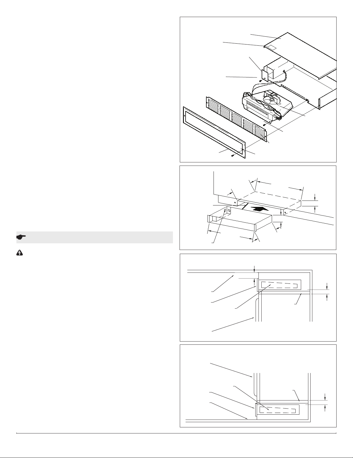
2. Cut 22 ⅜ in (568 mm) x 3 ⅝ in (92 mm) opening
(Figure 2). Keep clearance area free of obstructions.
3. Bring in service cable to left or rear of 10 in (254 mm)
minimum area as shown in Fig. 2.
4. Remove heater cover and appropriate knockout.
Attach service cable to unit with approved connector
and connect colour to colour in outlet box. To change
wattage or voltage connections, see Figure 5.
5. Replace cover, slide unit into opening, and secure
each side (Figure 1).
!
NOTE: Make sure unit is installed right side up.
Refer to “TOP” label.
For inspection of eld wiring, see instruction under
“Electrical Inspection”.
Soft or Stair Riser Installation
1. Cut opening as for heater installation (22 ⅜ in
(568 mm) x 3 ⅝ in (92 mm)). Allow ¾ in (19 mm)
clearance below cabinet doors. Add supports for unit
(Figure 3).
2. Proceed as for heater installation. After securing unit
in opening, install combination of frame and grille
(Figure 1).
FIGURE 1
Top Label
Screw ‘A’
FIGURE 2
Service
SERVICE
CABLE
Cable
Heater Cover
Junction Box Cover
Screw ‘C’
10" MIN.
10" MIN.
Screw‘B’
Grille
Optional Grille Frame
22-3/8"
22 3/8"
Heater
Element
3-5/8"
3 5/8"
Operation
WARNING: This heater must be properly installed
before it is used.
1. Prior to energization remove all construction dirt
(plaster, sawdust, etc.) from interior and exterior of
heater.
2. Adjust thermostat with pliers. This unit is also
controllable from a line voltage wall thermostat or
eld installed built-in tamperproof single or double
pole thermostat kit.
Dimplex Under Cabinet heaters are designed and tested
for safe and trouble-free operation and are protected
against overheating by a built-in thermal cutout. Free
airow throughout the heater is extremely important for
the most efcient operation of the heater. Restricted
airow may cause the thermal overload protector to
cycle the heater “ON and OFF”. A cycling heater will not
supply sufcient heat to the room.
Avoid direct contact of paper, fabric, or furniture with
heater.
KNOCKOUTS
Knockouts
FIGURE 3
CEILING
GRILLE
CABINET
DOOR
FIGURE 4
CABINET
DOOR
GRILLE
FLOOR
HEATER
HEATER
22"
22"
3-1/2"
3 1/2"
9-1/2"
9 1/2"
CLEARANCE 5" MIN.
PARTITION
OR ADDED
SUPPORT
PARTITION
OR ADDED
SUPPORT
3/4"
MIN.
3/4
MIN.
www.dimplex.com2
Page 3

Maintenance
WARNING: Disconnect power and heater has cooled
before attempting any maintenance or cleaning to
reduce the risk of re, electric shock or damage to
persons.
Remove grille and frame by removing screws “A”. Remove
two screws “B”, and slide out heating assembly. When
re-assembling, reverse the procedure above.
Cleaning
!
NOTE: This heater should not be operated with an
accumulation of dust or dirt on or in the unit, as this can
cause a build up of heat and eventual damage. For this
reason the heater must be inspected regularly, depending
upon conditions and at least at yearly intervals.
FIGURE 5
FACTORY CONNECTION
208/240 VOLT 675/900 WATTS
3.2 A / 3.7A
FIELD CONNECTION
208/240 VOLT 1350/1800 WATTS
6.5 A / 7.5 A
• With grille in place - Use vacuum cleaner hose to
suck out lint and dirt around grille. Reverse hose
on vacuum to use as a blower to move dust out of
enclosure. Reverse hose back to suck out dirt at
front area of heater.
• With grille removed - Remove two screws “B” at
bottom front of heating element assembly. Pull gently
to remove it from enclosure. Swing assembly out.
Vacuum inside of enclosure and around heating
element assembly. Reverse procedure above to reassemble unit.
FIELD CONNECTION
120 VOLT
M
FAN
IMPORTANT: RETIGHTEN ALL LEADS WITH CABLE CLAMP AFTER RECONNECTING
UNINSULATED ENDS OF UNUSED LEADS WITH WIRE NUTS
FAN
M
SAFETY SWITCH SAFETY SWITCHSAFETY SWITCH
FAN
M
RATING CONNECT
450W/ 3.75A 7-8 (AS SHOWN)
900W/ 7.5A 7-8, 1-2
1350W/ 11.2A 7-8, 1-2, 3-4
1800W/ 15A 7-8, 1-2, 3-4, 5-6
FIGURE 5a
NOTE: If installing unit with factory thermostat, see supplemental wiring diagram, Fig. 5a.
THERMOSTAT
Page 4

Warranty
The Manufacturer warrants the heating elements and
components of the enclosed product against any defect
in material or workmanship for a period of one year from
the date of purchase. In full satisfaction of any claims
under this Warranty the Manufacturer will repair or
replace without charge, in its factory or in the eld as
it alone may decide, any parts which in its opinion are
defective.
The Manufacturer shall not be responsible for any
transportation or shipping costs in relation to such repair
or replacement except as specically assumed by it.
Misuse of this product or repairs by persons other than
the Manufacturer’s authorized personnel without the
Manufacturer’s written approval, will void this Warranty.
This Warranty is in lieu of all other warranties or
conditions whether expressed or implied including but
not limited to those of merchantability or tness for
purpose and shall constitute the sole remedy of the
Purchaser and the sole liability of the Manufacturer
in respect of the sale of the product, whether in the
nature of breach or breach of fundamental term, or of
negligence or otherwise.
The Manufacturer shall not be liable for any special,
indirect or consequential damages or for any damages
resulting from removal or replacement of a heater
subject to warranty claim without the Manufacturer’s
authorization.
This Warranty is transferable by the original
consumer purchaser of the product. Any claims
under this Warranty must be submitted in writing
to the Service Manager, Dimplex North America
Ltd., 1367 Industrial Rd., Cambridge, Ontario
N3H 4W3, Canada.
Replacement Parts
Motor 2000280400RP
Fan Blade 5300210100RP
Element 22003260100RP
Cut out (Manual) 03005035RP
Cutout (Automatic) 211A619RP
Grill Kit (Black) CKHABG
Grill Kit (White) CKHAWG
Grill Kit (Silver) CKHASG
1367 Industrial Road Cambridge ON Canada N3H 4W3
1-888-346-7539 www.dimplex.com
In keeping with our policy of continuous product improvement, we reserve the right to make changes without notice.
© 2018 Dimplex North America Limited
 Loading...