

Dimplex RFV-800, RFV831551, RFV831551W, RFV831581, RFV831581W Installation & Operation Manual
...Page 1
7201010001rev10In keeping with our policy of continuous product development, we reserve the right to make changes without notice.
Dimplex North America Limited
1367 Industrial Road Cambridge ON Canada N1R 7G8
1-800-668-6663 www.dimplex.com
Installation, Operation &
Maintenance Instructions
Forced Air Heater
Series “D” RFV-800
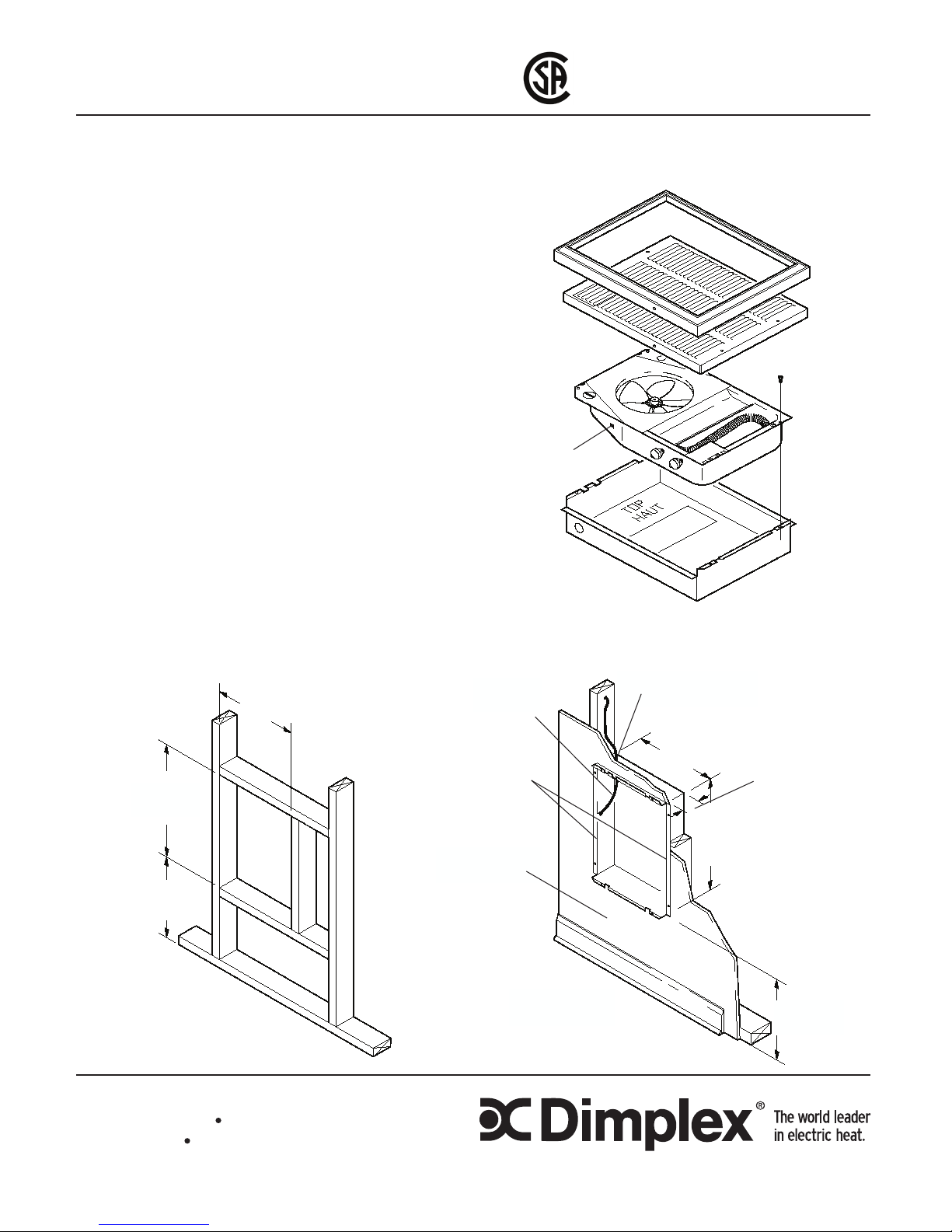
Remove heater from carton. The front grill and trim can
be lifted off assembly, and placed in carton to prevent
damage. Remove screws securing heater assembly to
the recess box and separate (Fig. 1).
NOTE: Mount the heater a minimum of 12 inches (30.5
cm) from the nished oor.
Recessed Installation
1. The recess box provided with the heater is designed
for attachment between studs placed on 16” (40.6cm)
centres. If different spacing exists, construct frame
to suit the box in order to avoid any vibration and
noise caused by loose mounting (Fig. 2a).
2. Note orientation of box (“TOP” shown on recess box)
and secure to studs using four holes provided on side
anges, ensuring these anges are ush with
nished surface of wall (Fig. 2b).
Surface Installation
1. Secure optional surface mount box (Part No. RFP8D)
by angling screws through holes provided in rear of
surface box into studs or nished surface.
2. Position recess box into surface box and secure with
four screws provided in parts bag of surface box.
Fig. 1
Ground
Screw
Front Panel (Grill)
& Trim Frame
Heater
Assembly
Recess Box
Fig. 2
19 3/4”
(50 cm)
MIN. 12”
(30.5 cm)
14 1/4”
(36 cm)
(a) (b)
Side
Flanges
15”
(38 cm)
Finished Wall
Surface
7/8” (22 mm) Dia.
Knockout
14 1/4”
(36 cm)
19 3/4”
(50 cm)
3 5/8”
(9 cm)
Finished
Floor
MIN. 12”
(30.5 cm)
NOTE: Dimensions are shown as
size of rough opening in stud wall
Page 2
Supply Wiring and Heater Installation
1. Insert approximately 15” (38cm) of supply wire into recess box
through knockout provided in upper left hand corner (Fig. 2b).
Wire should be rated for a minimum of 75°C (167°F)
2. Connect power supply to terminals provided marked L1 and L2.
Ground wire should be secured to green ground screw provided
on side of heater assembly (Fig. 1).
3. All units are factory prewired for operation with built-in thermostat.
If remote thermostat operation is required follow appropriate
wiring diagram located on inside of recess box.
NOTE: All wiring must comply with National Electrical Code and
local codes.
4. Secure heater assembly to recess box using four (4) M4 screws
removed at the start of these instructions.
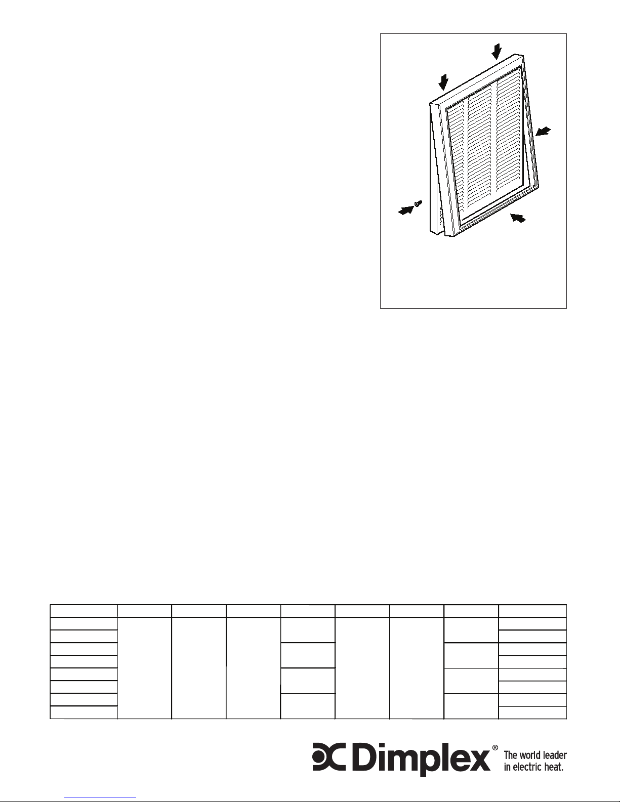
Front Panel Installation
1. Remove trim frame from front panel assembly.
2. If tamperproof built-in or remote thermostat operation is required,
secure the louvered door to the front panel using two (2) M3
screws (not included) through the holes provided. The knob can
then be removed and adjustment of the thermostat can be made using a slotted screwdriver through the front
panel.
3. Check to see that the fan blade is free to turn and that no residue remains in the unit. Front panel can then
be secured to assembly using four (4) M4.8 x 37 screws provided.
4. Follow the steps in Fig. 3.
Operation and Maintenance
1. Set thermostat to desired temperature and both fan and heat should come on. Note that when desired
temperature is reached the fan operation will continue for a short period after the elements have de energized in order to remove residual heat from the unit.
2. The fan motor is permanently lubricated and sealed at the factory and is maintenance free.
3. It is suggested that at the beginning of each season the front panel is removed and the wire connection
condition is checked and the unit is cleaned of dust and dirt with a vacuum cleaner.
NOTE: Always open the circuit breaker to disconnect power to the unit prior to performing any maintenance or
service operation.
WARNING: Should the Over Temp light come on, disconnect power to the heater or turn down the thermostat
fully counterclockwise and call a licenced electrician. DO NOT USE HEATER UNTIL PROBLEM IS
DETERMINED AND FIXED.
CATALOGUE NO. MOTOR CAPACITOR FAN BLADE ELEMENT CUT-OUT FAN DELAY THERMOSTAT FRONT PANEL KIT
RFV831551 RFVFPA
RFV831551W RFVFPW
RFV831581 RFVFPA
RFV831581W RFVFPW
RFV842051 RFVFPA
RFV842051W RFVFPW
RFV842081 RFVFPA
RFV842081W RFVFPW
2600060400RP
16210094RP
00029001RP
3200070100RP
REPLACEMENT PART
2000260100RP
00010034RP
16210091RP
00009114RP
00033002RP
2600060400RP
16210093RP
00029001RP
16210092RP
Fig. 3
A
B
C
C
(A) Place frame over top of tabs.
(B) Push in at bottom until frame is ush
with front panel.
(C) Insert two (2) screws to hold frame in
place.
 Loading...