

Dimplex RFI815D31-KIT, RFI820D31W-KIT, RFI815D31W-KIT, RFI820D31-KIT, RFI820D41-KIT Installation Instructions Manual
...Page 1
Forced Air Heater
RFI Series
IMPORTANT INSTRUCTIONS
When using electrical appliances, basic precautions should
always be followed to reduce the risk of re, electric shock
and injury to person, including the following:
Read all instructions before using this heater.1.
A heater has hot and arcing or sparking parts inside. Do 2.
not use it in areas where gasoline, paint or ammable
liquids are used or stored.
This heater is hot when in use. To avoid burns, do not let 3.
bare skin touch hot surfaces. If provided, use handles
when moving this heater. Keep combustible materials
such as: furniture, pillows, bedding, papers, clothes and
curtains away from heater.
To prevent a possible re, do not block air intakes or 4.
exhaust in any manner. Do not use on soft surfaces like
a bed where openings may become blocked.
Do not insert or allow foreign objects to enter any venti-5.
lation or exhaust opening as this may cause an electric
shock or re, or damage the heater.
SAVE THESE INSTRUCTIONS
Installation Instructions
WARNING: Wiring procedures and connections should
be in accordance with the National Electric code (NEC &
CEC) and local codes.
!
NOTE: Each heater comes as two packages: the main
heater assembly and the associated grille kit.
CAUTION: Do not operate heater without the Grille
installed.
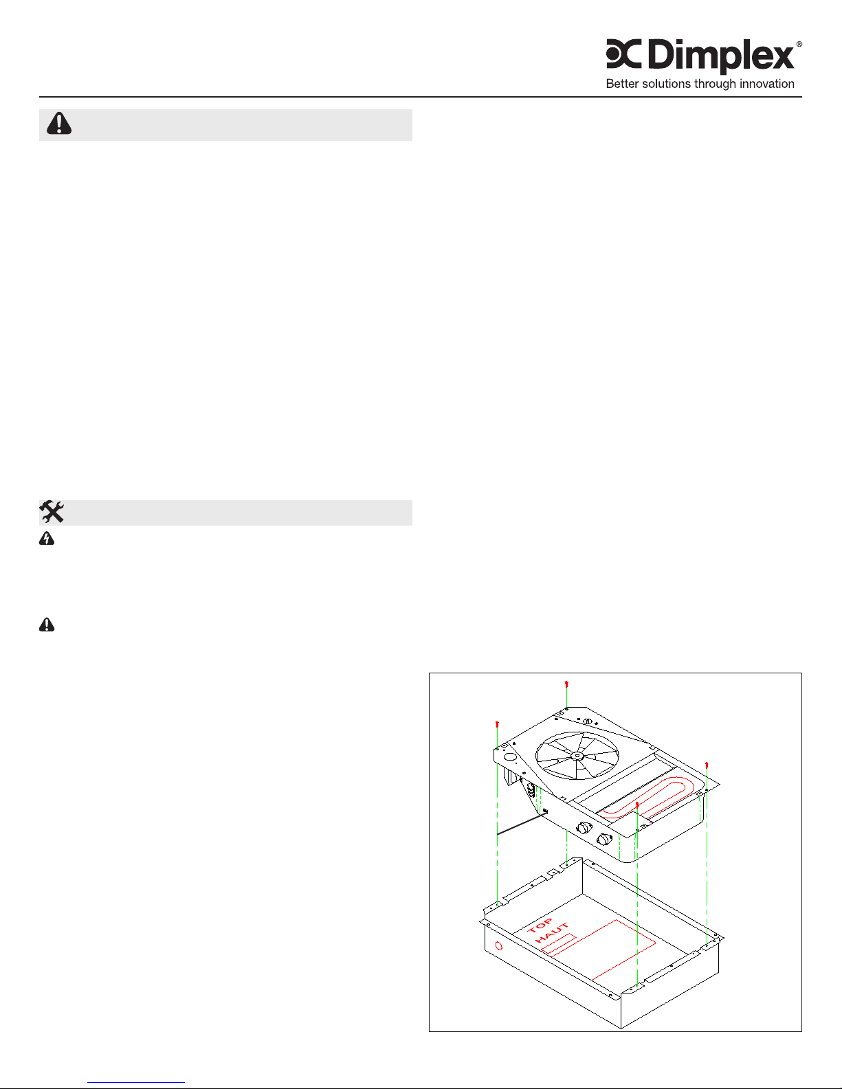
Remove the main heater assembly from the carton. Re-1.
move the screws securing heater assembly and retaining
brackets to the recess box and separate. (Figure 1) .
!
NOTE: Mount the heater a minimum of 12” (30.5cm)
from the nished oor, and a minimum of 6” (15cm) from any
vertical surface if installed in the ceiling.
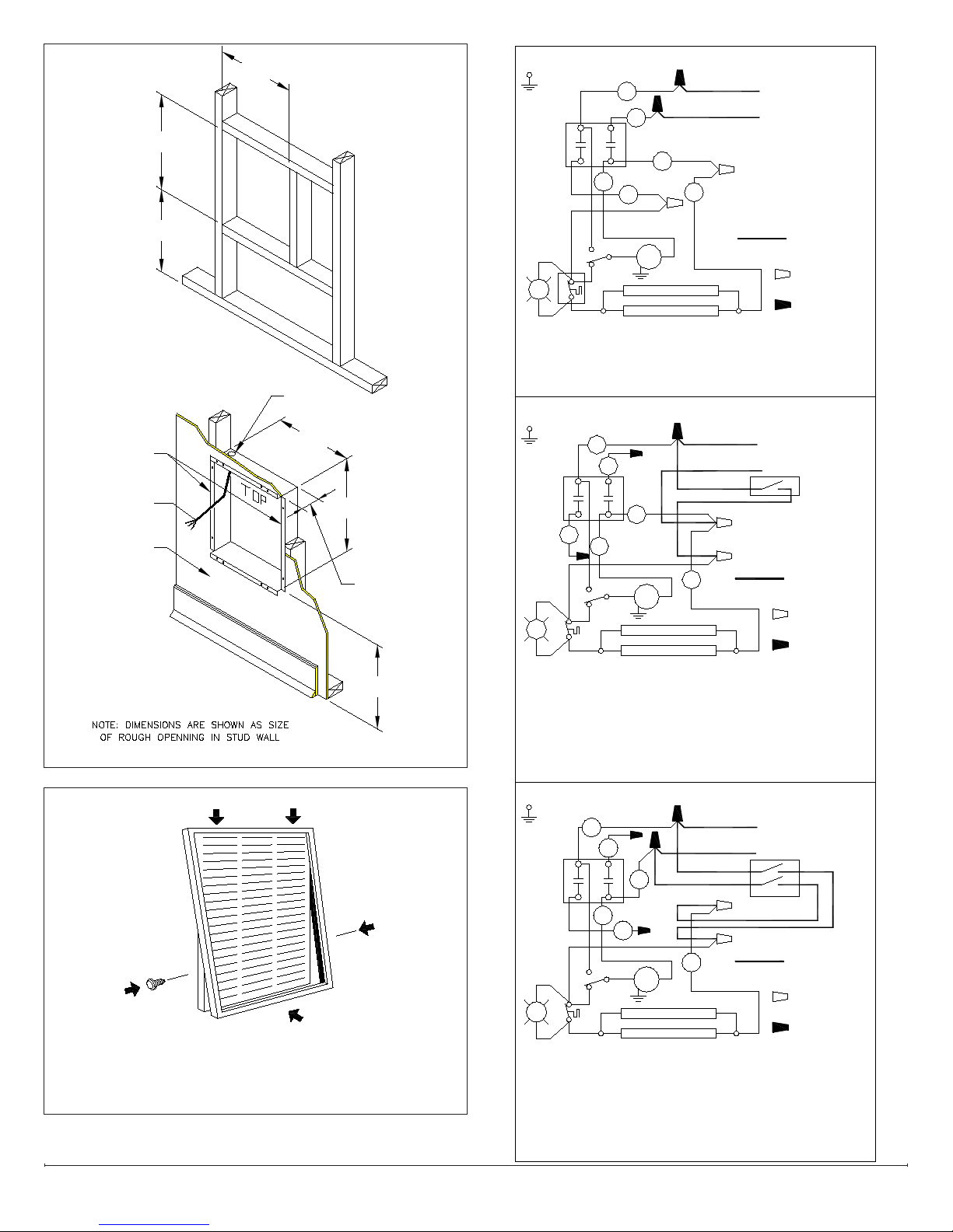
Recessed Installation
The recess box provided with the heater is designed for 2.
attachment between studs placed on 16” (40.6cm) centres. If different spacing exists, construct frame to suit
the box in order to avoid any vibration and noise caused
by loose mounting (Figure 2a).
Note the orientation of box (“TOP” shown on recess 3.
box) and secure to studs using four holes provided on
side anges, ensuring these anges are ush with nished surface of wall or ceiling (Figure 2b).
Surface Installation
2. Secure optional surface mount box (Part No. RFP8D)
by angling screws through holes provided in rear of
surface box into studs or nished surface.
3. Position recess box into surface box and secure with
four screws provided in parts bag of surface box.
Supply Wiring and Heater Installation
Insert approximately 15” (38cm) of supply wire into 4.
recess box through knockout provided in upper left hand
corner (Figure 2b). Wire should be rated for a minimum
of 75°C (167°F)
Connect power supply to terminals provided marked L1 5.
and L2. Ground wire should be secured to green ground
screw provided on side of heater assembly (Figure 1).
All units are factory prewired for operation with built-in 6.
thermostat. If remote thermostat operation is required
follow appropriate wiring diagram located on inside of
recess box.
!
NOTE: It is recommended that for ceiling mount applications a remote thermostat be used in order to provide superior temperature control.
!
NOTE: All wiring must comply with National Electrical
Code and local codes.
Secure heater assembly into recess box using the four 7.
M4 screws previously removed.
Front Panel Installation
Remove trim frame and front panel (grille) from the 8.
carton.
If tamper proof built-in or remote thermostat operation 9.
is required, secure the louvered door to the front panel
using 2 M3 screws (not included) through the holes provided. The knob can then be removed and adjustment
of the thermostat can be made using needle nose pliers
through the front panel.
Install the front panel on the heater assembly. Check to 10.
see that the fan blade is free to turn and that no residue
remains in the unit. Front panel can then be secured to
assembly using four M4.8 x 37 screws provided.
Follow the steps as shown in Figure 3.11.
Figure 1
HEATER
ASSEMBLY
GROUND
SCREW
RECESS BOX
7211900100R00
Page 2
FINISHED WALL
SURFACE
SIDE FLANGES
15"
[38cm]
min. 12"
[30.5cm]
3 5/8"
[9cm]
14 1/4"
[36cm]
19 3/4"
[50cm]
7/8"[22mm] DIA
KNOCKOUT
FINISH FLOOR
19 3/4"
[50cm]
14 1/4"
[36cm]
min. 12"
[30.5cm]
Figure 2
L
L
L
WIRING
CUSTOMER
SUPPLY
BUILT-IN THERMOSTAT (FACTORY WIRED)
OFF
CYCLE
GRND.
UNIT
THERMOSTAT
L1L2
3
2
1
M
UNIT
GRND.
S.P. "LINE" VOLTAGE REMOTE THERMOSTAT
D.P. "LINE" VOLTAGE REMOTE THERMOSTAT
GRND.
UNIT
L2
L1
A
B
FACTORY
SUPPLIED
SUPPLIED
CUSTOMER
CUSTOMER
SUPPLIED
SUPPLIED
FACTORY
B
A
L1
L2
M
1
2
3
L2 L1
THERMOSTAT
CYCLE
OFF
SUPPLY
CUSTOMER
WIRING
REMOTE
SP STAT
DP STAT
REMOTE
WIRING
CUSTOMER
SUPPLY
OFF
CYCLE
THERMOSTAT
L1L2
3
2
1
M
L2
L1
A
B
FACTORY
SUPPLIED
SUPPLIED
CUSTOMER
NOTE:
THIS WIRING REPRESENTS THE UNIT AS FACTORY WIRED.
PLEASE CONSULT THE OTHER DIAGRAMS SHOWN AS TO
WHAT OPTION IS REQUIRED. PLEASE ASSURE THAT ALL
1. MARR/TAPE WIRE LABELLED "L1" FROM THERMOSTAT
AS SHOWN.
2. DISCONNECT WIRE "B" FROM MARR CONNECTOR "B",
REMOVE FROM THERMOSTAT CONNECTOR AND DISCARD.
3. CONNECT INCOMING SUPPLY "L1" TO CONNECTOR "A"
4. CONNECT LOAD SIDE OF REMOTE LINE VOLTAGE
THERMOSTAT TO MARR CONNECTOR "B" AS SHOWN.
5. CONNECT INCOMING POWER WIRE "L2" TO BOTH THE LINE
1. MARR/TAPE WIRE LABELLED "L1" FROM THERMOSTAT
AS SHOWN.
2. DISCONNECT WIRE "B" FROM MARR CONNECTOR "B",
REMOVE FROM THERMOSTAT CONNECTOR AND DISCARD.
3. CONNECT LOAD SIDES OF REMOTE WALL THERMOSTAT TO
MARR CONNECTORS "A" AND "B" AS SHOWN IN DIAGRAM.
CONNECTIONS MADE ARE SECURE AND THAT ALL ELECTRICAL
CLEARANCES ARE MET.
A
B
C
B
A
C
D
B
C
L1
L2
L2
L1
L1
L2
SIDE OF REMOTE WALL THERMOSTAT AND WIRE ATTACHED
TO BUILT IN THERMOSTAT WIRE LABELLED "L2" AS SHOWN.
4. CONNECT WIRE "A" TO INCOMING SUPPLY "L1".
5. CONNECT THE OTHER INCOMING POWER SUPPLY LINE TO
THE OTHER LINE SIDE OF REMOTE WALL THERMOSTAT
AS SHOWN.
D
A
D
B
C
C
A
A
B
Figure 3
(A) Place frame over top of tabs.
(B) Push in at bottom until frame is ush with front panel.
(C) Insert two screws to hold frame in place.
www.dimplex.com2
Page 3

Operation and Maintenance
Set thermostat to desired temperature and both fan and 1.
heat should come on. Note that when desired temperature is reached the fan operation will continue for a short
period after the elements have de-energized in order to
remove residual heat from the unit.
The fan motor is permanently lubricated, sealed at the 2.
factory and is maintenance free.
It is suggested that at the beginning of each season the 3.
front panel is removed and the wire connection condition
is checked and the unit is cleaned of dust and dirt with a
vacuum cleaner.
!
NOTE: Always open the circuit breaker to disconnect
power to the unit prior to performing any maintenance or
service operation.
WARNING: Should the Over Temp light come on, discon-
nect power to the heater or turn down the thermostat fully
counterclockwise and call a licensed electrician. DO NOT
USE HEATER UNTIL THE CAUSE OF THE PROBLEM IS
DETERMINED AND FIXED.
Warranty
The Manufacturer warrants the heating elements and components
of the enclosed product against any defect in material or
workmanship for a period of one year from the date of purchase. In
full satisfaction of any claims under this Warranty the Manufacturer
will repair or replace without charge, in its factory or in the eld as it
alone may decide, any parts which in its opinion are defective.
The Manufacturer shall not be responsible for any transportation
or shipping costs in relation to such repair or replacement except
as specically assumed by it. Misuse of this product or repairs by
persons other than the Manufacturer’s authorized personnel without
the Manufacturer’s written approval, will void this Warranty.
This Warranty is in lieu of all other warranties or conditions
whether express or implied including but not limited to those of
merchantability or tness for purpose and shall constitute the sole
remedy of the Purchaser and the sole liability of the Manufacturer in
respect of the sale of the product, whether in the nature of breach or
breach of fundamental term, or of negligence or otherwise.
The Manufacturer shall not be liable for any special, indirect or
consequential damages or for any damages resulting from removal
or replacement of a heater subject to warranty claim without the
Manufacturer’s authorization.
This Warranty is transferable by the original consumer purchaser
of the product. Any claims under this Warranty must be submitted
in writing to the Service Manager, Dimplex North America Ltd., 1367
Industrial Rd., Cambridge, Ontario N1R 7G8, Canada.
Replacement Parts
Fan Blade . . . . . . . . . . . . . . . . . . . . . . . . . . . . . . . . . . 00010034RP
Cut Out . . . . . . . . . . . . . . . . . . . . . . . . . . . . . . . . . . . . 00009112RP
Thermostat . . . . . . . . . . . . . . . . . . . . . . . . . . . . . . . . . 13678001RP
Thermostat Knob ............................. 13691001RP
CATALOGUE
NO.
RFI815D31-KIT
RFI815D31W-KIT RPIFPW
RFI820D31-KIT
RFI820D31W-KIT RPIFPW
RFI820D41-KIT
RFI820D41W-KIT RPIFPW
RFI830D31-KIT
RFI830D31W-KIT RPIFPW
RFI830D41-KIT
RFI830D41W-KIT RPIFPW
RFI840D21-KIT
RFI840D21W-KIT RPIFPW
RFI840D31-KIT
RFI840D31W-KIT RPIFPW
RFI840D41-KIT
RFI840D41W-KIT RPIFPW
RFI848D31-KIT
RFI848D31W-KIT RPIFPW
MOTOR CAPACITOR ELEMENT FAN DELAY
00013004RP
2000260600RP 3200070100RP
00013002RP
2000260200RP 3200070400RP 00013008RP 00033002RP
2000260600RP 3200070100RP 00013004RP 00033001RP
2000260200RP 3200070400RP 00013007RP 00033002RP
00013001RP
2000260600RP 3200070100RP
00013002RP
2000260200RP 3200070400RP 00013008RP 00033002RP
2000260600RP 3200070100RP 00013005RP 00033001RP
00033001RP
00033001RP
FRONT PANEL
KIT
RFIFPA
RFIFPA
RFIFPA
RFIFPA
RFIFPA
RFIFPA
RFIFPA
RFIFPA
RFIFPA
1367 Industrial Road Cambridge ON Canada N1R 7G8
1-888-346-7539 www.dimplex.com
In keeping with our policy of continuous product improvement, we reserve the right to make changes without notice.
© 2012 Dimplex North America Limited
3
 Loading...