

Page 1
1
2
3
4
RF Receiver
Installation and Operating Instructions
RFRE234001 Issue 1
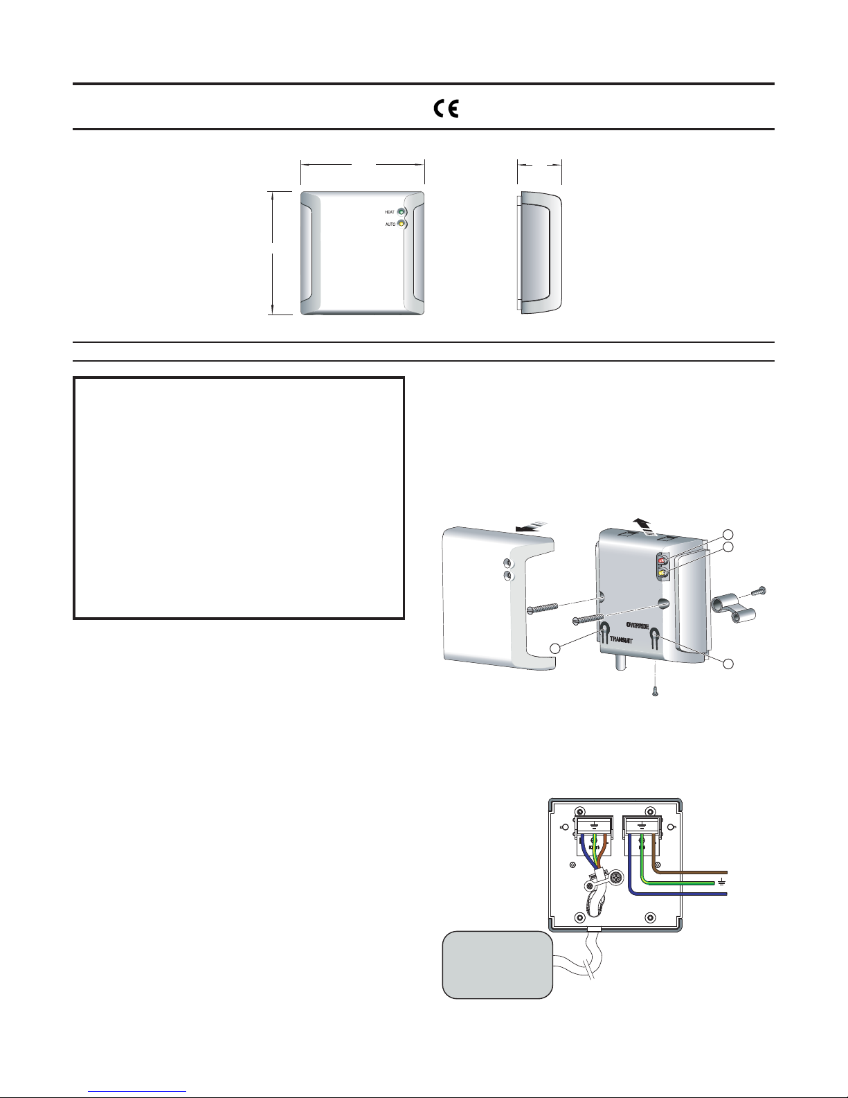
Fig. 1
IMPORTANT : THESE INSTRUCTIONS SHOULD BE READ CAREFULL Y AND RET AINED FOR FUTURE REFERENCE
Important Safety Advice
When using electrical appliances, basic precautions should
always be followed to reduce the risk of fire, electrical
shock, and injury to persons, including the following:
This product is splash proof to IP24 standard and may be
used in bathrooms in Zones 2 & 3 only, however not in the
immediate vicinity of baths, showers, water connections,
wash basins or swimming pools.
This unit must only be used on an A.C Mains supply of 230/
240V with products up to a maximum of 2kW.
Ensure that supply cables to the product are of adequate
current carrying capacity.
This product is used to control separate heating appliances.
Please note the safety guidelines of the controlled product
must be adhered to at all times.
General
The RF Receiver is to be used in conjunction with the RF Controller Unit
to provide wireless room temperature control for use with multiple heating
appliances. Note: Each appliance requires a Receiver Unit.
The Receiver can be used in conjunction with heating appliances with a
maximum heating capacity of 2kW. The Controller Unit cannot be used
with a Quartz Halogen heater without a suitable in-line contactor.
Installation
Before undertaking installation work, ensure the electricity supply is
disconnected from any relevant fixed wiring.
· All wiring should be carried out by a qualified electrician in accordance
with the current IEE wiring regulations.
· The Receiver unit is designed to be fitted to a standard single BS
backing box with a depth of at least 25mm. The backing box (not
supplied) should already be recessed into the wall.
Alternatively a surface mounted wall box may be used.
· Ensure the top and bottom lugs (if fitted) of metal backing boxes are
removed prior to installation.
Receiver
a) If the heating appliance to be used in conjunction with the Receiver
is fitted with a plug, please remove the plug and strip the wires to the
appropriate length.
b) Remove the screw from the underside of the unit . The front facia is
held in place by clips at the top. It must be removed by lifting the top
of the facia upwards and then outwards - see Fig. 2. The cable
clamp on the rear of the Receiver should then be removed.
c ) The cable of the heating appliance is fed through an opening on the
underside of the unit (see Fig. 3).
d) The cable from the heating appliance is then wired to the terminal
block labelled (out). Please ensure the wires are connected in
accordance with the marked terminals - see Fig. 3.
e) The cable from the heating appliance is then clamped to the rear of
the Receiver unit using the cable clamp previously removed.
f) Connect the fixed wiring of the premises from the backing box to the
clearly marked terminals on the Receiver unit (see Fig. 3). Please
ensure that the unit is earthed to the backing box.
g) Secure to the back box using the screws provided (located on rear
moulding) - see Fig. 2.
Note: The Receiver front facia should not be refitted until the unit has
been set up (see ‘Unit Set-Up’).
Receiver - see Fig. 2
1. ‘HEAT’ Indicator
2. ‘AUTO’ Indicator
3. ‘OVERRIDE’ button
4. ‘TRANSMIT’ button
Receiver Wiring - see Fig. 3
Fig. 3
Fig. 2
95
38
95
L
N
230/240V AC
L
N
L
N
HEATING
APPLIANCE
Page 2

Unit Set-Up
The Receiver must be synchronised to suit your individual Controller.
1. Remove the front facias from both the Controller and Receiver units.
(see ‘Installation’).
2. Ensure both the Controller and Receiver(s) are powered up. To
activate the Controller press the standby button see ‘1’ in Fig. 2.
When activated, the ‘ON’ (Green) light will illuminate.
3. Press the ‘TRANSMIT’ button on the Receiver. The Receiver goes
into synchronise mode. This is indicated by both the ‘AUTO’ (yellow)
and the ‘HEAT’ (Red) lights flashing. If more than one Receiver is to
be controlled by a single Controller all Receivers must similarly be put
into synchronise mode. Each Receiver will remain in synchronise
mode for approximately one minute.
4. With the Receiver(s) in the synchronise mode the ‘TRANSMIT’ button
on the Controller is then pressed. This puts the Controller in
synchronise mode, this is indicated by the Controller ‘HEAT’ (red)
and ‘BOOST’ (blue) lights flashing. The Controller will remain in
synchronise mode for approximately ten seconds.
5. The Receiver will automatically go into auto mode once a signal has
been received from the Controller. The Controller is ready once the
‘AUTO’ (yellow) light is lit on the Receiver.
6. The front facias should then be replaced on both the Controller and
Receiver, ensuring the bottom screw is replaced.
Operating Instructions
Please refer to ‘RF Controller Unit Instructions’.
Cleaning
WARNING: ALWAYS PLACE THE CONTROLLER IN STAND BY MODE
BEFORE CLEANING .
Do not use detergents, abrasive cleaning powders or polish of any kind
on the controller.
Wipe with a dry cloth to remove dust and a damp cloth (not wet) to clean
off stains. Be careful not to allow moisture into the heater.
Recycling
For electrical products sold within the European Community.
At the end of the electrical products useful life it should not be
disposed of with household waste. Please recycle where
facilities exist. Check with your Local Authority or retailer for
recycling advice in your country.
After sales service
Should you require after sales service or should you need to purchase
any spares, please contact the retailer from whom the appliance was
purchased. Please do not return a faulty product to us in the first instance
as this may result in loss or damage and delay in providing you with a
satisfactory service. Please retain your receipt as proof of purchase.
 Loading...