

Page 1
Ceiling-mounted Heater (with ConnexTM)
RCH5031CXW
IMPORTANT INSTRUCTIONS
When using electrical appliances, basic precautions should always
be followed to reduce the risk of re, electric shock and injury to person, including the following:
1. Read all instructions before using this heater.
2. The heater is hot when in use. To avoid burns, do not let bare
skin touch hot surfaces. Keep combustible materials, such as
furniture, pillows, bedding, papers, clothes, and curtains at least
a 3 ft. (1 m) from the front of the heater and keep them away
from the sides.
3. Wiring procedures and connections should be in accordance
with the National Electric Code (NEC & CEC) and local codes.
4. Extreme caution is necessary when any heater is used by or
near children or invalids and whenever the unit is left operating
and unattended.
5. Do not operate any heater after it malfunctions. Disconnect
power at service panel and have heater inspected by a certied
electrician before reusing.
6. To disconnect heater, turn off power to heater circuit at main dis-
connect panel.
7. Do not use outdoors.
8. Use this heater only as described in this manual. Any other use
not recommended by the manufacturer may cause re, electric
shock, or injury to persons.
9. A heater has hot and arcing or sparking parts inside. Do not use
it in areas where gasoline, paint or ammable liquids are used
or stored.
10. This heater is hot when in use. To avoid burns, do not let bare
skin touch hot surfaces. Keep combustible materials such as:
furniture, pillows, bedding, papers, clothes and curtains away
from heater.
11. Do not insert or allow foreign objects to enter any ventilation or
exhaust opening as this may cause an electric shock or re, or
damage the heater.
12. To prevent a possible re, do not block air intake or exhaust in
any manner.
!
NOTE: This equipment has been tested and found to comply with the limits
for a Class B digital device, pursuant to Part 15 of the FCC Rules. These limits
are designed to provide reasonable protection against harmful interference
in a residential installation. This equipment generates, uses and can radiate
radio frequency energy and, if not installed and used in accordance with
the instructions, may cause harmful interference to radio communications.
However, there is no guarantee that interference will not occur in a particular
installation. If this equipment does cause harmful interference to radio or
television reception, which can be determined by turning the equipment off
and on, the user is encouraged to try to correct the interference by one of the
following measures:
• Reorient or relocate the receiving antenna.
• Increase the separation between the equipment and receiver.
• Connect the equipment on a circuit different from that to which the
receiver is connected.
• Consult the dealer or an experienced radio/TV technician for help.
This device complies with Part 15 of the FCC Rules. Operation is subject
to the following two conditions: (1) This device may not cause harmful
interference, and (2) this device must accept any interference received,
including interference that may cause undesired operation.
FCC CAUTION: Any changes or modications not expressly approved by
the party responsible for compliance could void the user’s authority to operate
this equipment.
This device complies with Industry Canada licence-exempt RSS standard(s).
Operation is subject to the following two conditions: (1) this device may not
cause interference, and (2) this device must accept any interference, including
interference that may cause undesired operation of the device.
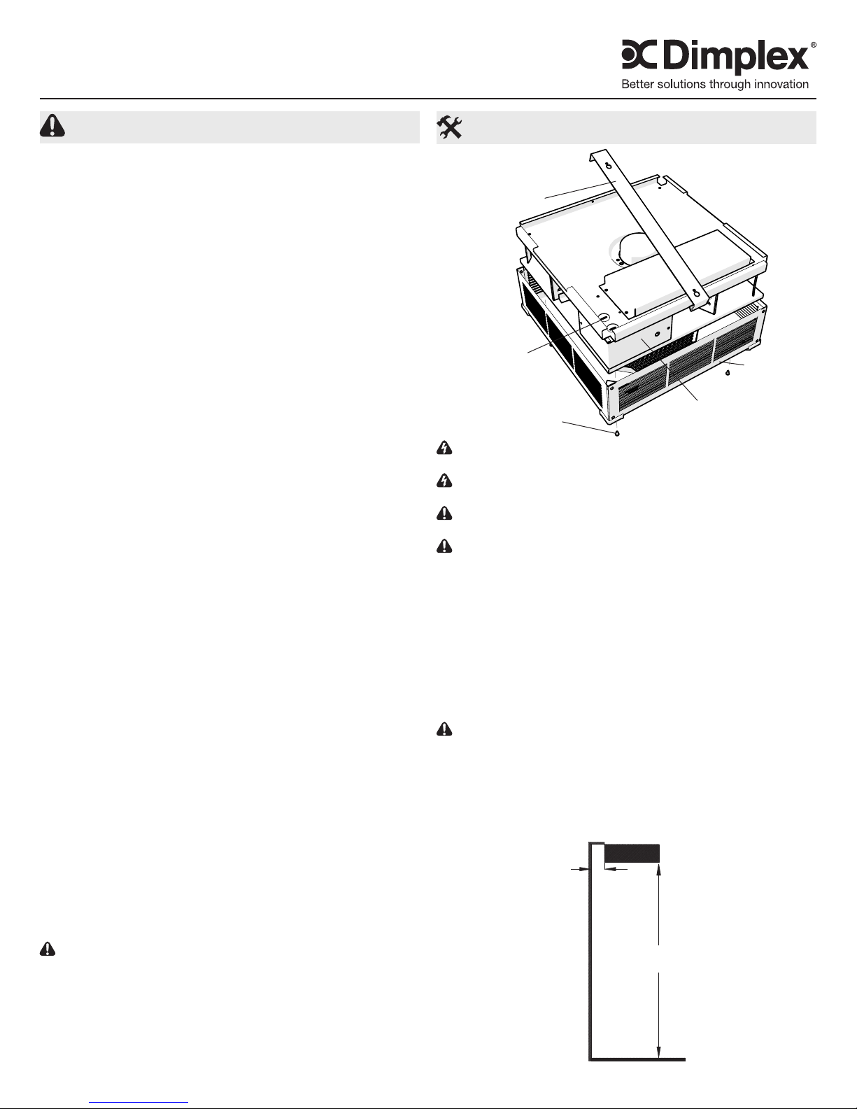
Installation Instructions
Figure 1
Mounting
Bracket
Electrical
Knockouts
Securing
Screws
WARNING: Wiring procedures and connections should be in ac-
cordance with the National Electric code (NEC) and local codes.
WARNING: To reduce the risk of re, do not store or use gasoline
or other ammable vapors and liquids in the vicinity of the heater.
CAUTION: The heater should be mounted for DOWNWARD dis-
charge only.
CAUTION: High temperature, risk of re, keep electrical cords,
drapery, furnishings, and other combustibles at least 3 feet (0.9m)
from the front of the heater and away from the side and rear.
1. Unpack the heater from the carton.
2. With the unit outlet pointing up, using the provided allen key,
remove the 4 screws to remove the grill box off of the unit.
3. Flip the unit over and loosen 1 screw to remove the mounting
bracket.
4. Determine the desired location, keeping in mind the minimum
clearances indicated in Figure 2.
5. Secure the mounting bracket to the ceiling.
CAUTION: The ceiling and mounting hardware must have adequate strength to support the heater. Attachment to a rm support
is a necessity.
6. Loosen 2 screws to remove the wiring compartment cover. (Fig-
ure 1)
7. Remove the desired knockout from the terminal box.
!
NOTE: It is only necessary to remove the knockout(s) that will
Wiring Compartment
Cover
Figure 2
MINIMUM
6" (15.3 cm)
MINIMUM
8' (244 cm)
Grill Box
SAVE THESE INSTRUCTIONS
7213980100R01
Page 2
feed the power supply wiring, keeping in mind the heater mounting
1
G
location and supply wire location.
8. Hang the heater from the hooked edge of the mounting bracket.
9. Connect power supply the wires to the wires in the unit - black
(L1) and white (L2). Ground wire should be secured to the green
wire provided inside of the heater.
WARNING: All wiring must be installed by a certied electrician
according to the electrical safety. The ceiling heater must be ground-
ed in accordance with all national and local building codes.
CAUTION: Ensure that the wires are located as to not cover or
apply pressure on the temperature sensor.
10. Replace the wiring compartment cover and replace with the 2
screws.
11. Swing the heater upwards to secure the opposite side of the
heater to the bracket and secure with previously removed
screws.
12. Replace the grill box.
WARNING: TO PREVENT THE RISK OF FIRE OR INJURY, DO
NOT OPERATE THE HEATER UNLESS IT IS FULLY ASSEMBLED.
Initial Set Up
After the unit has been installed, calibration of the unit to the area
will be required. This can be done by closing all doors and windows
to the room and turning the unit ON. When the unit is initially turned
on there is a 28 minute period of calibration of the unit where the
software runs at full power for 20 minutes, then runs for 8 minutes to
cool the heater down.
If the unit is relocated or the size of the area that it is installed in chan-
ges, it is recommended that the unit be reset to the factory default to
allow the unit to recalibrate.
Factory Default
1. Press and hold the V for 3 seconds. Both the and icons
will begin to ash.
2. Within 5 seconds press ✚, then ✚, then –, then –, then V,
then –.
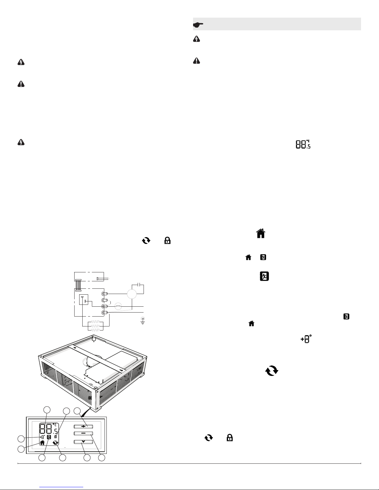
Wiring Diagram
POWER PCB
SENSORCONTROL PCB
T3
T4
K1
T1
T2
CUTOUT
M
L
L2
Operation Instructions
WARNING: This heater is factory pre-wired for operation with the
built-in thermostat. THIS HEATER IS NOT TO BE USED WITH A
REGULAR WALL THERMOSTAT.
CAUTION: This heater must be properly installed before it is used.
The RCH is designed with heating elements that will turn on and off
based on the built-in temperature sensor to maintain a constant room
temperature.
!
NOTE: The element retains heat after shutdown, there is a built
in cool down period of 5 minutes before the fan shuts off completely.
Manual Controls
(See Figure 3 for display reference)
When power is rst supplied to the RCH the Set point Temperature will
ash in the temperature display area. At any time either the ✚ or – but-
ton can be pressed to have the temperature set point displayed again.
A. Setting/Temperature Display
The RCH is designed to control the temperature of a room from 41104°F (5-40 °C). By pressing the ✚ or – will increase or decrease
the desired temperature for the room to be heated by 0.5° (in either
°C or °F).
When adjusting the Set point Temperature the display will switch
back to display the ambient temperature after 5 seconds.
!
NOTE: The unit can be set to run continuously as a fan by setting
the temperature at 41 °F (5 °C). At this temperature the heater will
not turn on.
!
NOTE: Pressing the ✚ and – at the same time will toggle be-
tween °C and °F.
B. Comfort Setting
The Comfort Setting icon will be displayed when the heater is in normal operation based on the Set point Temperature for the room.
!
NOTE: Either the or icon will always be visible, dependent
on the setting being used.
C. Economy Setting
The Economy Setting can be used to change the Set point Temperature for a user determined period of time. By pressing the V the
Economy Setting will be enabled - signied by the icon ashing. After
the Set Back Temperature has been set, the icon will become solid
after three seconds and the Set Back Temperature will be enabled.
To return back to the Comfort Setting press the V button. The icon
will disappear and the icon will appear.
Figure 3
A - Setting/Temperature Display
A
H
F
D
B
C
E
I
B - Comfort Setting Icon
C - Economy Setting Icon
D - Set Back Temperature Setting
E - Synchronized Icon
F - Lock Icon
G - Decrease Button
H - Increase Button
I - Menu Button
G
D. Set Back Temperature Setting
The Set Back Temperature Setting is used during periods when the
Economy setting feature is active. This temperature adjustment can
be set by pressing the V followed by the ✚ or –.
E. Synchronized Icon
The RCH features CONNEXTM, a wireless technology that works with
Dimplex single and multi-zone CONNEXTM controllers to provide simple whole home connectivity and comfort (a single zone controller is
included). CONNEXTM controllers are available to control one or multiple CONNEX
for the controller to have this function the RCH and the controller will
need to be synchronized. To do this:
1. On the RCH press and hold the V button for 3 seconds, both the
2. Press the – , ✚ and then V, on the RCH.
3. Within 10 seconds press any button once on the
CONNEXTM Controller.
TM
series heaters within a 50’ (15 m) radius. In order
and icons will begin to ash.
www.dimplex.com2
Page 3

!
NOTE: There is a 3 second delay between pressing the last button
on the controller and the RCH.
!
NOTE: To desynchronize a RCH from the synchronized CON-
NEXTM Controller; on either the RCH or the controller:
1. Press and hold the V for 3 seconds.
2. Press the V, ✚ and then –.
Nothing will need to be done to the other component.
The Dimplex multi-zone CONNEXTM controller is sold separately and
is available for purchase from your authorized Dimplex dealer.
To nd your local Dimplex dealer, visit www.dimplex.com.
F. Lock Icon
The RCH has a Lock feature to prevent settings from accidentally
being changed.
1. Press and hold the V for 3 seconds. Both the and Icons
will begin to ash.
2. To Enable: Within 5 seconds press ✚, then –, then ✚, then –.
The icon will appear
To Disable: Within 5 seconds press –, then ✚, then –, then ✚.
The icon will disappear.
!
NOTE: The RCH can be locked in either the Comfort or Economy
Setting. Ensure that the desired icons are present when locking is
complete.
Warranty
The Manufacturer warrants the RCH series ceiling heaters and components of the enclosed product against any defect in material or
workmanship for a period of one year from the date of purchase. In
full satisfaction of any claims under this Warranty the Manufacturer
will repair or replace without charge, in its factory or in the eld as it
alone may decide, any parts which in its opinion are defective.
The Manufacturer shall not be responsible for any transportation or
shipping costs in relation to such repair or replacement except as
specically assumed by it. Misuse of this product or repairs by persons other than the Manufacturer’s authorized personnel without the
Manufacturer’s written approval, will void this Warranty.
This Warranty is in lieu of all other warranties or conditions whether
express or implied including but not limited to those of merchantability or tness for purpose and shall constitute the sole remedy of
the Purchaser and the sole liability of the Manufacturer in respect of
the sale of the product, whether in the nature of breach or breach of
fundamental term, or of negligence or otherwise.
The Manufacturer shall not be liable for any special, indirect or consequential damages or for any damages resulting from removal or
replacement of a heater subject to warranty claim without the Manufacturer’s authorization.
This Warranty is transferable by the original consumer purchaser
of the product. Any claims under this Warranty must be submitted
in writing to the Service Manager, Dimplex North America Ltd., 1367
Industrial Rd., Cambridge, Ontario N1R 7G8, Canada.
Maintenance Instructions
WARNING: Always disconnect power at the circuit breaker to the
unit prior to performing any maintenance or service operation.
CAUTION: Allow adequate time for the element and body casing
to cool before attempting to work on the heater.
It is suggested that the heater be inspected regularly, for cleanliness
of the fan intake and exhaust grilles, to ensure optimal performance
is maintained. The grilles can be cleaned either by vacuuming off
all dust and dirt or, washing the grille box in warm, soapy water and
allowing to dry thoroughly before reinstalling. Once cleaning is com-
plete replace the grille and restore power.
WARNING: TO PREVENT THE RISK OF FIRE OR INJURY, DO
NOT OPERATE THE HEATER UNLESS IT IS FULLY ASSEMBLED.
At least at yearly intervals the wire connection condition should be
inspected to ensure full electrical continuity and optimal performance
is maintained.
WARNING: The user can perform cleaning ONLY. All other servic-
ing should be performed by qualied service personnel.
Replacement Parts
Cutout .................................RCH-CUTOUT-RP
Fan Blade ..................................RCH-FAN-RP
Motor ...................................RCH-MOTOR-RP
Housing Cover .........................RCH-COVER-CX-RP
Display Board .......................CMH-DISPLAYPCB-RP
Power Board .........................RCH-POWERPCB-RP
Temperature Sensor .........................2500620200RP
CONNEXTM Controllers
Single Controller ............................DPCRWS
Multi-zone Controller ..........................CX-MPC
1367 Industrial Road Cambridge ON Canada N1R 7G8
1-888-346-7539 www.dimplex.com
In keeping with our policy of continuous product improvement, we reserve the right to make changes without notice.
© 2015 Dimplex North America Limited
 Loading...