

Page 1
Service Manual
Model
RBF30
RBF36
RBF36P
RBF42
Part Number
6909780100
6909790100
6909790200
6909800100
IMPORTANT SAFETY INFORMATION: Always read this manual rst before attempting to service this rebox. For your
safety, always comply with all warnings and safety instructions contained in this manual to prevent personal injury or property damage.
Dimplex North America Limited
1367 Industrial Road Cambridge ON Canada N3H 4W3
1-888-346-7539 www.dimplex.com
In keeping with our policy of continuous product development, we reserve the right to make changes without notice.
© 2017 Dimplex North America Limited
REV PCN DATE
00 - 12-JAN-17
7400970000R00
Page 2

TABLE OF CONTENTS
Operation ...........................................................3
Maintenance .........................................................5
Exploded Parts Diagram ...............................................6
Replacement Parts List ................................................6
Wiring Diagram ......................................................7
Log Set Assembly Replacement ........................................8
Flame Screen Replacement ............................................8
Ember LED Light Replacement .........................................9
Flame Base LED Replacement ..........................................9
Back Log LED Replacement ............................................9
Flicker Motor Replacement. . . . . . . . . . . . . . . . . . . . . . . . . . . . . . . . . . . . . . . . . . . . 10
Main Control Board Replacement ......................................10
Power Supply Replacement ...........................................11
Blower Assembly Replacement ........................................11
Element Replacement ................................................12
Cutout Replacement .................................................13
Main Control Assembly Replacement ...................................13
Thermistor Replacement .............................................14
Top Front Lights Replacement .........................................14
Troubleshooting Guide ...............................................15
Always use a qualied technician or service agency to repair this rebox.
!
NOTE: Procedures and techniques that are considered important enough to emphasize.
CAUTION: Procedures and techniques which, if not carefully followed, will result in damage to the equipment.
WARNING: Procedures and techniques which, if not carefully followed, will expose the user to the risk of re, serious
injury, or death.
2 www.dimplex.com
Page 3
OPERATION
Figure 1
Figure 3
A
H
C
F
E
B
D
I
G
J
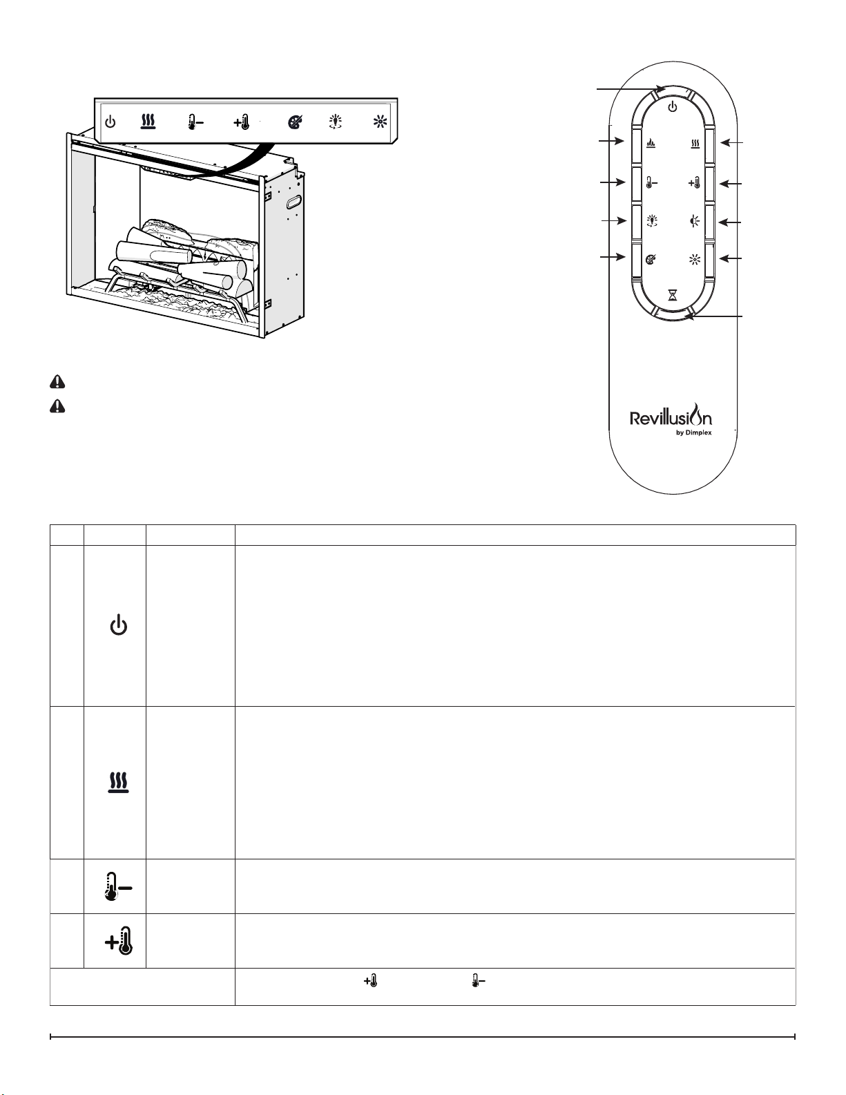
Touch Panel and Remote Controls
TM
WARNING: The Revillusion
CAUTION: Except for installation and cleaning described in this manual, an authorized service representative should
perform any other servicing.
The manual controls for the RevillusionTM Built-in Electric Firebox are located on the front panel. Touch an icon to activate.
The selected setting displays on the left side of the panel.
A multi-function remote control also is provided. The remote control has a range of approximately 30 ft (9 m). To operate
correctly, the remote control must be pointed toward the front of the built-in electric rebox.
Icon Function Description
A
B
Power/
Standby
Heat
Built-in Electric Firebox must be installed properly before it is used.
Press to activate the current standby state (On/Off).
•Standby State On
Press to turn everything Off. Press again to activate the previous state.
•Standby State Off
Press to activate the previous state.
- If the ame effect was On, the previous heat setting will be activated (On or Off).
- If the ame effect was Off, the previous heat setting will be activated (High or Low).
Press again to turn everything Off.
• Heat On
Press to turn heat On (indicated by 1 short beep and the icon appearing on the display).
Displays current heater temperature setting. Use the Temp Up/Down icon to change the
heater temperature setting.
• Heat Off
Press to turn heat Off (indicated by 1 short beep).
C
D
Change Fahrenheit (0 F) to
Celsius (0 C)
Temp Down
Temp Up
NOTE: After the heater is switched off, the fan will continue on for 60 seconds before
!
turning off.
Press multiple times to lower the heater temperature in 10 F (10 C) increments. Displays
current temperature; lowest temperature is 410 F (50 C). This feature is active whenever
the heat is enabled.
Press multiple time to raise the heater temperature in 10 F (10 C) increments. Displays
current temperature; highest temperature is 990 F (370 C). This feature is active whenever
the heat is enabled.
Press both Temp+ ( ) and Temp– ( ) on the unit.
3
Page 4
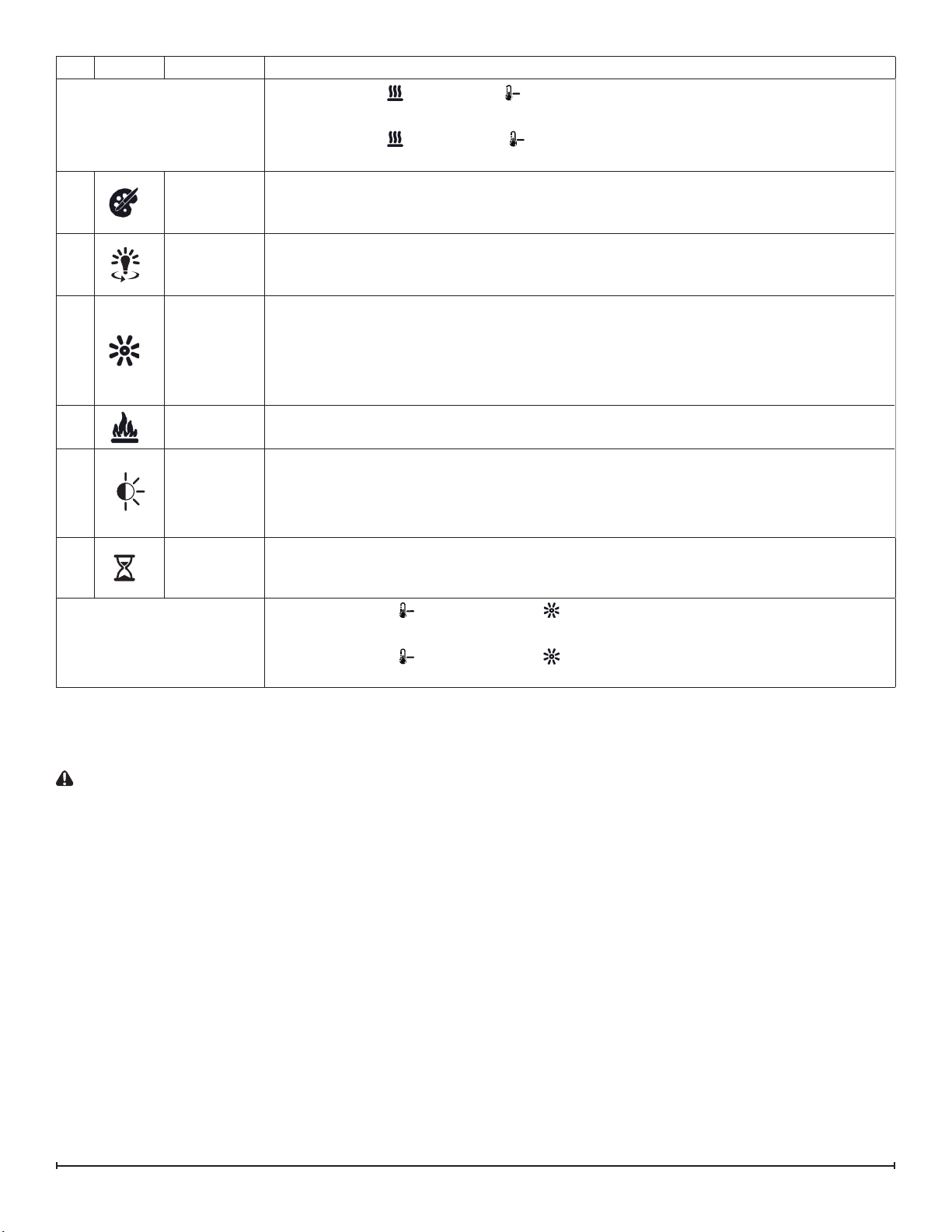
Icon Function Description
Heat Enable
Hold both Heat ( ) and Temp– ( ), on the unit, for 2 seconds. Temperature displays
on the screen.
Heat Disable
E
F
G
H
I
J
Color
Themes
360o Light
Brightness
Flame
Light
Sensor
Timer
Hold both Heat ( ) and Temp– ( ), on the unit, for 2 seconds, when temperature is
adjusted "---" displays on the screen.
Press multiple times to change the ame base colors from Red to Blue to Off. (The rst
segment on the display will change from "r" to "b" to blank) This feature is active only
when the ame effect is On.
Press multiple times to change the LEDs on the sides and back of the unit from Midnight
mode to white to yellow to red. (The middle segment on the display will change through
0 - 3 respectively. This feature is active only when the Flame is ON.)
Press to change the LED lights from High to Low. (The last segment on the display will
change from "H" to "L") The RealogTM LEDs remain On when the heater is ON and the
ame effect is Off.
NOTE: When the Light Sensor is activated, High and Low ickering brightness
!
settings are also available (Flashing "H" and "L").
Press to light the log set and start the ame effect. Press again to turn feature Off.
Press to activate the ambient light sensor (ALS ON). Press again to turn the sensor off
(ALS OFF).
NOTE: The light sensor will adjust the brightness of the replace based on the
!
ambient light in the room.
Press multiple times to change the sleeper timer in 0.5 hr increments from 0.5 hr to 8.0 hr
before turning off. The remaining time on the sleep timer displays.
Control Lock
Control Unlock
Hold both Temp– ( ) and Brightness ( ), on the unit, for 2 seconds to disable the
manual controls.
Hold both Temp– ( ) and Brightness ( ), on the unit, for 2 seconds to enable the
manual controls.
Resetting the Temperature Cutoff Switch
Should the heater overheat, an automatic cut out will turn the heater off and it will not come back on without being reset. It
can be reset by disconnecting power at the main electrical panel and waiting 5 minutes before plugging the unit back in.
CAUTION: If you need to con tinuously reset the heater, unplug the unit and call technical support at 1-888-346-7539.
4 www.dimplex.com
Page 5

MAINTENANCE
General Maintenance
Inspect the built-in electric rebox regularly, depending
upon conditions, and at a minimum yearly intervals.
Remove dust and clean the logs, grate, and base as
required.
WARNING: Disconnect power and allow heater to cool
before attempting any maintenance or cleaning to reduce
the risk of re, electric shock, or injury.
CAUTION: Except for installation and cleaning
described in this manual, an authorized service
representative should perform any other servicing.
Clean Logs and Base
The built-in electric rebox set should not be operated with
an accumulation of dust or dirt on or in the rebox, as this
can cause a build up of heat and eventual damage.
Dust and vacuum the rebox as needed. Use a damp cloth
and a mild detergent to clean painted surfaces of the built-
in electric rebox. Never use abrasive cleaners.
CleanReectorScreen
The reector screen is cleaned in the factory during the
assembly operation. During shipment, installation, handling,
etc., the screen may collect dust particles; these can be
removed by dusting lightly with a clean dry cloth.
To remove ngerprints or other marks, clean the reector
screen damp cloth. Never use abrasive cleaners. Dry the
screen completely with a lint free cloth to prevent water
spots.
Remote Battery Replacement
To replace the battery:
1. Push down on the battery cover located on the back of
the remote control. Slide the battery cover open.
2. Install 3V (CR2032) Lithium battery in the battery
holder. The positive (+) side of the battery faces up.
3. Close the battery cover.
The old battery must be recycled or disposed of properly.
Check with your Local Authority or Retailer for recycling
advice in your area.
CAUTION: When transporting or storing the heater and cord,
keep in a dry place, free from excessive vibration and store so as
to avoid damage.
5
Page 6
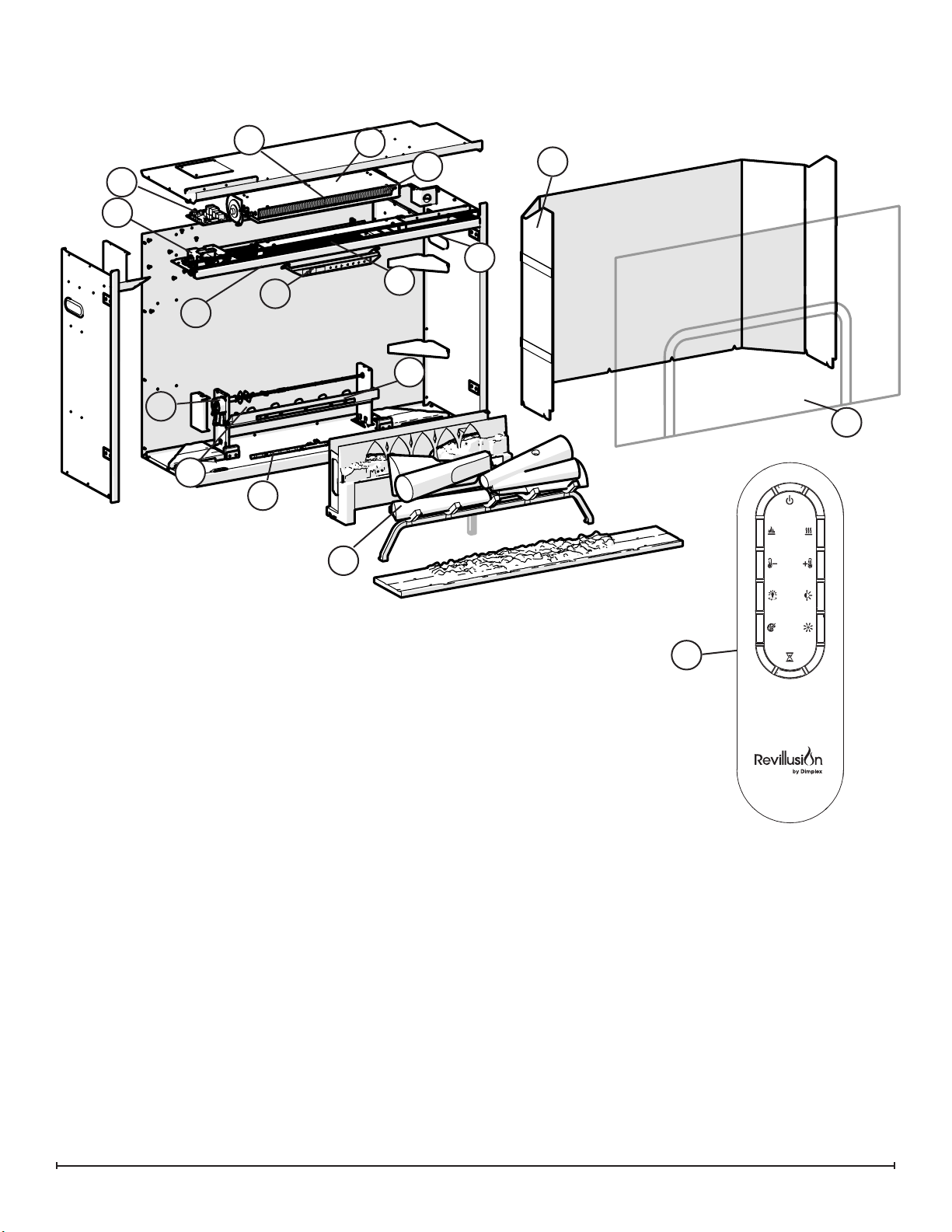
EXPLODED PARTS DIAGRAM
6
4
5
17
2
1
14
9
3
13
10
7
15
11
12
16
REPLACEMENT PARTS LIST
1. Power Supply . . . . . . . . . . . . . . . . . . . . . . . . . 2100250100RP
2. Main Control Board ....................3001810101RP
3. Control Assembly . . . . . . . . . . . . . . . . . . . . . . 3001830100RP
4. Blower Assembly ......................5300110500RP
5. Heater Elements. . . . . . . . . . . . . . . . . . . . . . . 2200510700RP
6. Cutout. . . . . . . . . . . . . . . . . . . . . . . . . . . . . . . 2300201900RP
7. Flicker Motor. . . . . . . . . . . . . . . . . . . . . . . . . . 2000501000RP
8. Remote Control .......................3001710100RP
9. Thermistor ...........................3001560800RP
10. Flame Base (RGB) RBF30. . . . . . . . . . . . . . . 3001790100RP
RBF36, RBF36P, RBF42
11. Back log LED RBF30 . . . . . . . . . . . . . . . . . . . 3001760200RP
RBF36, RBF36P, RBF42
12. Ember LED RBF30. . . . . . . . . . . . . . . . . . . . . 3001820100RP
RBF36, RBF36P, RBF42
13. Top Back Light (RGB). . . . . . . . . . . . . . . . . . . 3001570100RP
3001790200RP
.....3001760300RP
. . . . . . . 3001820200RP
8
14. Top Front Lights (2 sets) RBF30 ..........3001570600RP
RBF36, RBF36P 3001570500RP
RBF42. . . . . . . . . . . 3001570401RP
15. Flame Screen RBF30. . . . . . . . . . . . . . . . . . . 5903010100RP
RBF36. . . . . . . . . . . . . . . . . . . 5903020100RP
RBF36P .................5903020300RP
RBF42. . . . . . . . . . . . . . . . . . . 5903020200RP
16. Log Set Assembly RBF30 ...............0442100100RP
RBF36, RBF36P, RBF42
17. Brick Panels RBF30 (LH & RH) ...........5902970001RP
RBF36 (LH) ................5902950001RP
RBF36P. . . . . . . . . . . . . . . . . . . 5903060001RP
RBF42 (LH) ................5902960001RP
0442110100RP
6 www.dimplex.com
Page 7

WIRING DIAGRAM
M
M
7
Page 8

LOG SET ASSEMBLY REPLACEMENT
Tools Required: Philips head screwdriver
FLAME SCREEN REPLACEMENT
Tools Required: Philips head screwdriver
WARNING: If the rebox was operating prior to servic-
ing, allow at least 10 minutes for the heating elements to
cool off to avoid accidental burning of skin.
WARNING: Disconnect power before attempting any
maintenance to reduce the risk of electric shock or damage
to persons.
1. Remove the front glass or any accessories that are
around the replace and will inhibit your ability to fully
access the unit.
2. Locate and remove the screw behind each of the front
legs of the rebox. (Figure 3)
!
IMPORTANT: Only handle the log-set by the plastic
grate, not the logs themselves.
3. Slide the rebox assembly forward and lift out.
!
NOTE: It may be necessary to slide the ember mat
forward and backward, and possibly out, as well to assist
with the removal.
4. Trace the wire from the back of the harness to the con-
nector that will be located in the middle slightly under
the ame screen.
5. Disconnect the old log set assembly and connect the
new one.
6. Place the connector back under the ame screen.
7. Install the replacement logs and secure with the two
screws that were previously removed.
8. Re-assemble the remainder of the rebox in reverse
order from the instructions above.
WARNING: If the rebox was operating prior to servic-
ing, allow at least 10 minutes for the heating elements to
cool off to avoid accidental burning of skin.
WARNING: Disconnect power before attempting any
maintenance to reduce the risk of electric shock or damage
to persons.
1. Remove the front glass or any accessories that are
around the replace and will inhibit your ability to fully
access the unit.
2. Locate and remove the screw behind each of the front
legs of the rebox. (Figure 3)
!
IMPORTANT: Only handle the log-set by the plastic
grate, not the logs themselves.
3. Slide the log set assembly forward and lift the log set
assembly and the ember mat out. (Figure 3)
!
NOTE: The log set assembly has a wire attached to
the unit which can be temporarily disconnected for easier
access.
4. On either side of the rebox gently remove the brick
panels by placing you nger in the gap and pulling
forward. The brick panels are held in place by magnets
and need minimal force to be removed.
5. Locate the two brackets securing the ame panel in the
unit at the bottom and remove the 4 screws.
6. Gently lift the ame panel out and replace with the new
one.
7. Re-assemble the unit in reverse order from the instruc-
tions above.
Figure 3
Log Set
Assembly
Flicker
Motor
Back Log
Back Log
LED
Flame Panel
Brackets
Ember
LED Light
Flame
Base LED
8 www.dimplex.com
Page 9

EMBER LED LIGHT REPLACEMENT
Tools Required: Philips head screwdriver
Needle-nose pliers
WARNING: If the rebox was operating prior to servic-
ing, allow at least 10 minutes for the heating elements to
cool off to avoid accidental burning of skin.
WARNING: Disconnect power before attempting any
maintenance to reduce the risk of electric shock or damage
to persons.
1. Remove the front glass or any accessories that are
around the replace and will inhibit your ability to fully
access the unit.
2. Locate and remove the screw behind each of the front
legs of the rebox. (Figure 3)
!
IMPORTANT: Only handle the log-set by the plastic
grate, not the logs themselves.
3. Slide the log set assembly forward and lift the log set
assembly and the ember mat out. (Figure 3)
!
NOTE: The log set assembly has a wire attached to
the unit which can be temporarily disconnected for easier
access.
4. Locate the two ember LED light assemblies and the
connector at the left hand side. (Figure 3)
5. Disconnect the connector.
6. Squeeze the mounting tabs located along the board
with the needle-nose pliers, to release the tabs and lift
off.
7. Replace the LED light assemblies with the new assem-
blies.
8. Re-assemble the unit in reverse order from the instruc-
tions above.
FLAME BASE LED REPLACEMENT
Tools Required: Philips head screwdriver
WARNING: If the rebox was operating prior to servic-
ing, allow at least 10 minutes for the heating elements to
cool off to avoid accidental burning of skin.
WARNING: Disconnect power before attempting any
maintenance to reduce the risk of electric shock or damage
to persons.
1. Remove the front glass or any accessories that are
around the replace and will inhibit your ability to fully
access the unit.
2. Locate and remove the screw behind each of the front
legs of the rebox. (Figure 3)
!
IMPORTANT: Only handle the log-set by the plastic
grate, not the logs themselves.
3. Slide the log set assembly forward and lift the log set
assembly and the ember mat out. (Figure 3)
!
NOTE: The log set assembly has a wire attached to
the unit which can be temporarily disconnected for easier
access.
4. On either side of the rebox gently remove the brick
panels by placing you nger in the gap and pulling
forward. The brick panels are held in place by magnets
and need minimal force to be removed.
5. Locate the two brackets securing the ame panel in the
unit at the bottom and remove the 4 screws. (Figure 3)
6. Gently lift the ame panel out, set aside in a safe location.
7. Remove the back log assembly by removing the two
screws along the front of the log and the screw on
either end.
8. Lift the back log assembly out of the unit.
9. Locate the ame base LED assembly and remove the
light strip by pressing in the tab in the center of the
stand offs to release the center pin out the back and lift
the light strip off. (Figure 3)
10. DIsconnect the light strip by pulling the connector out of
the assembly on the left hand side.
11. Connect the new light strip.
12. Re-assemble the unit in reverse order from the instructions above.
BACK LOG LED REPLACEMENT
Tools Required: Philips head screwdriver
Needle-nose pliers
WARNING: If the rebox was operating prior to servic-
ing, allow at least 10 minutes for the heating elements to
cool off to avoid accidental burning of skin.
WARNING: Disconnect power before attempting any
maintenance to reduce the risk of electric shock or damage
to persons.
1. Remove the front glass or any accessories that are
around the replace and will inhibit your ability to fully
access the unit.
2. Locate and remove the screw behind each of the front
legs of the rebox. (Figure 3)
!
IMPORTANT: Only handle the log-set by the plastic
grate, not the logs themselves.
3. Slide the log set assembly forward and lift the log set
assembly and the ember mat out. (Figure 3)
!
NOTE: The log set assembly has a wire attached to
the unit which can be temporarily disconnected for easier
access.
4. On either side of the rebox gently remove the brick
panels by placing you nger in the gap and pulling
forward. The brick panels are held in place by magnets
and need minimal force to be removed.
5. Locate the two brackets securing the ame panel in the
unit at the bottom and remove the 4 screws. (Figure 3)
6. Gently lift the ame panel out, set aside in a safe loca-
tion.
7. Remove the back log assembly by removing the two
screws along the front of the log and the screw on
9
Page 10

either end.
8. Lift the back log assembly out of the unit.
9. Locate the ame base LED assembly and squeeze the
mounting tabs located along the board with the needlenose pliers, to release the tabs and lift off.
10. DIsconnect the light strip by pulling the connector out of
the assembly on the left hand side.
11. Connect the new light strip.
12. Re-assemble the unit in reverse order from the instructions above.
FLICKER MOTOR REPLACEMENT
Tools Required: Philips head screwdriver
WARNING: If the rebox was operating prior to servic-
ing, allow at least 10 minutes for the heating elements to
cool off to avoid accidental burning of skin.
WARNING: Disconnect power before attempting any
maintenance to reduce the risk of electric shock or damage
to persons.
1. Remove the front glass or any accessories that are
around the replace and will inhibit your ability to fully
access the unit.
2. Locate and remove the screw behind each of the front
legs of the rebox. (Figure 3)
!
IMPORTANT: Only handle the log-set by the plastic
grate, not the logs themselves.
3. Slide the log set assembly forward and lift the log set
assembly and the ember mat out. (Figure 3)
!
NOTE: The log set assembly has a wire attached to
the unit which can be temporarily disconnected for easier
access.
4. On either side of the rebox gently remove the brick
panels by placing you nger in the gap and pulling
forward. The brick panels are held in place by magnets
and need minimal force to be removed.
5. Locate the two brackets securing the ame panel in the
unit at the bottom and remove the 4 screws. (Figure 3)
6. Gently lift the ame panel out, set aside in a safe loca-
tion.
7. Remove the back log assembly by removing the two
screws along the front of the log and the screw on
either end.
8. On the left hand side, locate the motor cover and
remove the two screws securing it to the rebox. The
cover can be gently tilted back and lifted out to access
the wire connections. (Figure 3)
9. Remove the two screws that secure the motor to the
unit.
10. Disconnect the icker rod and rubber grommet from the
icker motor.
11. Disconnect the wire connectors, noting the location of
the wires and connect the new motor wires.
12. Re-assemble the unit in reverse order from the instruc-
tions above.
WARNING: Ensure wires do not get pinched while rein-
stalling the motor cover.
MAIN CONTROL BOARD REPLACEMENT
Tools Required: Philips head screwdriver
Flat Head Screwdriver
WARNING: If the rebox was operating prior to servic-
ing, allow at least 10 minutes for the heating elements to
cool off to avoid accidental burning of skin.
WARNING: Disconnect power before attempting any
maintenance to reduce the risk of electric shock or damage
to persons.
1. Remove the front glass or any accessories that are
around the replace and will inhibit your ability to fully
access the unit.
2. Slide the log set assembly forward and lift the log set
assembly and the ember mat out. (Figure 3)
!
NOTE: The log set assembly has a wire attached to
the unit which can be temporarily disconnected for easier
access.
3. On either side of the rebox gently remove the brick
panels by placing you nger in the gap and pulling
forward. The brick panels are held in place by magnets
and need minimal force to be removed.
4. Locate the two brackets securing the ame panel in the
unit at the bottom and remove the 4 screws. (Figure 3)
5. Gently lift the ame panel out, set aside in a safe loca-
tion.
6. Remove the 2 hex head screws on either side of the
controls and the 4 hex head screws along each side
of the panel and gently lower the internal assembly.
(Figure 4)
7. Disconnect the two main wire connectors - one on each
side of the unit.
8. Disconnect the hanging straps at the front, ensuring
that you support the entire assembly, and lift the back
of the assembly up and off of the hook at the back. At
this point you should be able to gently set the assembly
on the surface infront of the unit to easily replace the
main control board.
9. Transfer the wire connectors from the terminals on the
original board to the same location on the replacement
board. (Figure 4)
!
NOTE: Use a at head screwdriver to gently pry be-
tween the end of the connector and the main control board
to release the wires.
10. Remove the screws in each of the corners of the board
and lift the board off.
11. Install the new board..
12. Re-assemble the remainder of the rebox in reverse
order from the instructions above.
10 www.dimplex.com
Page 11

Figure 4
Main Control
Board
Power
Supply
Thermistor
Main Control
Assembly
Cutout
Element
Blower
Assembly
Hex Head
Screws
Top Front Lights
WARNING: Ensure wires do not come in contact with
moving parts by securing wires in wiring tie wraps.
POWER SUPPLY REPLACEMENT
Tools Required: Philips head screwdriver
Flat Head Screwdriver
WARNING: If the rebox was operating prior to servic-
ing, allow at least 10 minutes for the heating elements to
cool off to avoid accidental burning of skin.
WARNING: Disconnect power before attempting any
maintenance to reduce the risk of electric shock or damage
to persons.
1. Remove the front glass or any accessories that are
around the replace and will inhibit your ability to fully
access the unit.
2. Slide the log set assembly forward and lift the log set
assembly and the ember mat out. (Figure 3)
!
NOTE: The log set assembly has a wire attached to
the unit which can be temporarily disconnected for easier
access.
3. On either side of the rebox gently remove the brick
panels by placing you nger in the gap and pulling
forward. The brick panels are held in place by magnets
and need minimal force to be removed.
4. Locate the two brackets securing the ame panel in the
unit at the bottom and remove the 4 screws. (Figure 3)
5. Gently lift the ame panel out, set aside in a safe loca-
tion.
6. Remove the 2 hex head screws on either side of the
controls and the 4 hex head screws along each side
of the panel and gently lower the internal assembly.
(Figure 4)
7. Disconnect the two main wire connectors - one on each
side of the unit.
8. Disconnect the hanging straps at the front, ensuring
that you support the entire assembly, and lift the back
of the assembly up and off of the hook at the back. At
this point you should be able to gently set the assembly
on the surface infront of the unit to easily replace the
main control board.
9. Locate the power supply located below the main control board. (Figure 4)
10. Remove the 4 screws that secure the main control
board to the unit.
11. Remove the 4 screws on the assembly to release the
bracket that secures the power supply to the unit.
12. Trace the wires to the main control board and the wire
nuts and replace the old connections with the new connections.
13. Reinstall the support bracket over the new power supply.
14. Re-assemble the remainder of the rebox in reverse
order from the instructions above.
WARNING: Ensure wires do not come in contact with
moving parts by securing wires in wiring tie wraps.
BLOWER ASSEMBLY REPLACEMENT
Tools Required: Philips head screwdriver
Flat Head Screwdriver
WARNING: If the rebox was operating prior to servic-
ing, allow at least 10 minutes for the heating elements to
cool off to avoid accidental burning of skin.
WARNING: Disconnect power before attempting any
maintenance to reduce the risk of electric shock or damage
11
Page 12

to persons.
1. Remove the front glass or any accessories that are
around the replace and will inhibit your ability to fully
access the unit.
2. Slide the log set assembly forward and lift the log set
assembly and the ember mat out. (Figure 3)
!
NOTE: The log set assembly has a wire attached to
the unit which can be temporarily disconnected for easier
access.
3. On either side of the rebox gently remove the brick
panels by placing you nger in the gap and pulling
forward. The brick panels are held in place by magnets
and need minimal force to be removed.
4. Locate the two brackets securing the ame panel in the
unit at the bottom and remove the 4 screws. (Figure 3)
5. Gently lift the ame panel out, set aside in a safe loca-
tion.
6. Remove the 2 hex head screws on either side of the
controls and the 4 hex head screws along each side
of the panel and gently lower the internal assembly.
(Figure 4)
7. Disconnect the two main wire connectors - one on each
side of the unit.
8. Disconnect the hanging straps at the front, ensuring
that you support the entire assembly, and lift the back
of the assembly up and off of the hook at the back. At
this point you should be able to gently set the assembly
on the surface infront of the unit to easily replace the
main control board.
9. From the top panel of the heating assembly housing,
locate and remove the 6 screws that hold the blower/
fan assembly to the housing panel. Separate the
blower assembly from the housing panel. (Figure 4)
CAUTION: When removing the blower assembly mount-
ing screws support the assembly to prevent any damage to
the unit.
10. Disconnect the wiring connections noting their original
locations.
!
NOTE: Using a at head screwdriver gently pry
between the end of the connectors and the blower/fan to
release the wires.
11. Properly orient the new blower/fan assembly and con-
nect all of the wiring connections.
12. Re-assemble the remainder of the rebox in reverse
order from the instructions above.
WARNING: Ensure wires do not come in contact with
moving parts by securing wires in wiring tie wraps.
ELEMENT REPLACEMENT
Tools Required: Philips head screwdriver
Flat Head Screwdriver
WARNING: If the rebox was operating prior to servic-
ing, allow at least 10 minutes for the heating elements to
cool off to avoid accidental burning of skin.
WARNING: Disconnect power before attempting any
maintenance to reduce the risk of electric shock or damage
to persons.
1. Remove the front glass or any accessories that are
around the replace and will inhibit your ability to fully
access the unit.
2. Slide the log set assembly forward and lift the log set
assembly and the ember mat out. (Figure 3)
!
NOTE: The log set assembly has a wire attached to
the unit which can be temporarily disconnected for easier
access.
3. On either side of the rebox gently remove the brick
panels by placing you nger in the gap and pulling
forward. The brick panels are held in place by magnets
and need minimal force to be removed.
4. Locate the two brackets securing the ame panel in the
unit at the bottom and remove the 4 screws. (Figure 3)
5. Gently lift the ame panel out, set aside in a safe loca-
tion.
6. Remove the 2 hex head screws on either side of the
controls and the 4 hex head screws along each side
of the panel and gently lower the internal assembly.
(Figure 4)
7. Disconnect the two main wire connectors - one on each
side of the unit.
8. Disconnect the hanging straps at the front, ensuring
that you support the entire assembly, and lift the back
of the assembly up and off of the hook at the back. At
this point you should be able to gently set the assembly
on the surface infront of the unit to easily replace the
main control board.
9. From the top panel of the heating assembly housing,
remove the 4 screws that hold the element cover to the
housing panel. (Figure 4)
10. Disconnect wires from the ends of the elements noting
their original locations.
!
NOTE: Using a at head screwdriver gently pry be-
tween the end of the connectors and the element to release
the wires.
!
NOTE: Some of the wires may have a “piggy-back”
connector that allows a second wire to connect to the same
prong as the rst wire. Try and keep the “piggy-back” connection together when pulling the wires off the element.
11. Using a 3/8” ratchet or wrench remove the hex head
screw from both sides of the element. Remove elements from the element housing and replace with the
new elements.
12 www.dimplex.com
Page 13

12. Re-assemble the remainder of the rebox in reverse
order from the instructions above.
WARNING: Ensure wires do not come in contact with
moving parts by securing wires in wiring tie wraps.
14. Re-assemble the remainder of the rebox in reverse
order from the instructions above.
WARNING: Ensure wires do not come in contact with
moving parts by securing wires in wiring tie wraps.
CUTOUT REPLACEMENT
Tools Required: Philips head screwdriver
Flat Head Screwdriver
WARNING: If the rebox was operating prior to servi-
cing, allow at least 10 minutes for the heating elements to
cool off to avoid accidental burning of skin.
WARNING: Disconnect power before attempting any
maintenance to reduce the risk of electric shock or damage
to persons.
1. Remove the front glass or any accessories that are
around the replace and will inhibit your ability to fully
access the unit.
2. Slide the log set assembly forward and lift the log set
assembly and the ember mat out. (Figure 3)
!
NOTE: The log set assembly has a wire attached to
the unit which can be temporarily disconnected for easier
access.
3. On either side of the rebox gently remove the brick
panels by placing you nger in the gap and pulling
forward. The brick panels are held in place by magnets
and need minimal force to be removed.
4. Locate the two brackets securing the ame panel in the
unit at the bottom and remove the 4 screws. (Figure 3)
5. Gently lift the ame panel out, set aside in a safe loca-
tion.
6. Remove the 2 hex head screws on either side of the
controls and the 4 hex head screws along each side
of the panel and gently lower the internal assembly.
(Figure 4)
7. Disconnect the two main wire connectors - one on each
side of the unit.
8. Disconnect the hanging straps at the front, ensuring
that you support the entire assembly, and lift the back
of the assembly up and off of the hook at the back. At
this point you should be able to gently set the assembly
on the surface infront of the unit to easily replace the
main control board.
9. Remove the 3 heater assembly mounting screws from
underneath the top panel along the front. (Figure 4)
10. Lower the heater assembly so that the 3 support tabs,
in the top panel, can be easily released.
11. Remove temperature limit switch screw from heater
bracket assembly and disconnect the temperature limit
switch wire from heater element and from the wire connectors, noting their original location.
12. Properly orient the new temperature limit switch and
secure it to the heater bracket assembly with the small
screw from the original cutout.
13. Reconnect the wires in their original locations.
MAIN CONTROL ASSEMBLY REPLACEMENT
Tools Required: Philips head screwdriver
Flat Head Screwdriver
WARNING: If the rebox was operating prior to servic-
ing, allow at least 10 minutes for the heating elements to
cool off to avoid accidental burning of skin.
WARNING: Disconnect power before attempting any
maintenance to reduce the risk of electric shock or damage
to persons.
1. Remove the front glass or any accessories that are
around the replace and will inhibit your ability to fully
access the unit.
2. Slide the log set assembly forward and lift the log set
assembly and the ember mat out. (Figure 3)
!
NOTE: The log set assembly has a wire attached to
the unit which can be temporarily disconnected for easier
access.
3. On either side of the rebox gently remove the brick
panels by placing you nger in the gap and pulling
forward. The brick panels are held in place by magnets
and need minimal force to be removed.
4. Locate the two brackets securing the ame panel in the
unit at the bottom and remove the 4 screws. (Figure 3)
5. Gently lift the ame panel out, set aside in a safe loca-
tion.
6. Remove the 2 hex head screws on either side of the
controls and the 4 hex head screws along each side
of the panel and gently lower the internal assembly.
(Figure 4)
7. Locate the main control assembly and remove the 2
screws on either side to release the assembly. (Figure
4)
8. Trace the wire from the main control assembly to the
main control board and disconnect the wire, noting the
location on the board.
9. Run the wire from the main control assembly, following
the same path as the wire that was removed. Attach
the new wire to the board.
10. Install the replacement control assembly and secure
with the 4 screws that were previously removed.
11. Re-assemble the remainder of the rebox in reverse
order from the instructions above.
WARNING: Ensure wires do not come in contact with
moving parts by securing wires in wiring tie wraps.
13
Page 14

THERMISTOR REPLACEMENT
Tools Required: Philips head screwdriver
Flat Head Screwdriver
WARNING: If the rebox was operating prior to servic-
ing, allow at least 10 minutes for the heating elements to
cool off to avoid accidental burning of skin.
WARNING: Disconnect power before attempting any
maintenance to reduce the risk of electric shock or damage
to persons.
1. Remove the front glass or any accessories that are
around the replace and will inhibit your ability to fully
access the unit.
2. Slide the log set assembly forward and lift the log set
assembly and the ember mat out. (Figure 3)
!
NOTE: The log set assembly has a wire attached to
the unit which can be temporarily disconnected for easier
access.
3. On either side of the rebox gently remove the brick
panels by placing you nger in the gap and pulling
forward. The brick panels are held in place by magnets
and need minimal force to be removed.
4. Locate the two brackets securing the ame panel in the
unit at the bottom and remove the 4 screws. (Figure 3)
5. Gently lift the ame panel out, set aside in a safe loca-
tion.
6. Remove the 2 hex head screws on either side of the
controls and the 4 hex head screws along each side
of the panel and gently lower the internal assembly.
(Figure 4)
7. Locate the thermistor and tie wrap securing it to the
standoff. (Figure 4)
8. Trace the wire from the thermistor to the main control
board and disconnect the wire, noting the location on
the board.
9. Run the wire from the thermistor, following the same
path as the wire that was removed. Attach the new wire
to the board.
10. Install the replacement thermistor and secure.
11. Re-assemble the remainder of the rebox in reverse
order from the instructions above.
WARNING: Ensure wires do not come in contact with
moving parts by securing wires in wiring tie wraps.
around the replace and will inhibit your ability to fully
access the unit.
2. Slide the log set assembly forward and lift the log set
assembly and the ember mat out. (Figure 3)
!
NOTE: The log set assembly has a wire attached to
the unit which can be temporarily disconnected for easier
access.
3. On either side of the rebox gently remove the brick
panels by placing you nger in the gap and pulling
forward. The brick panels are held in place by magnets
and need minimal force to be removed.
4. Locate the two brackets securing the ame panel in the
unit at the bottom and remove the 4 screws. (Figure 3)
5. Gently lift the ame panel out, set aside in a safe loca-
tion.
6. Remove the 2 hex head screws on either side of the
controls and the 4 hex head screws along each side
of the panel and gently lower the internal assembly.
(Figure 4)
7. Locate the 2 top front light assemblies and from the
backside of the standoff press the center out to release
the center pin and more the light assembly. (Figure 4)
8. Disconnect the connection on each end, replace with
the new light assembly and secure.
9. Re-assemble the remainder of the rebox in reverse
order from the instructions above.
WARNING: Ensure wires do not come in contact with
moving parts by securing wires in wiring tie wraps.
TOP FRONT LIGHTS REPLACEMENT
Tools Required: Philips head screwdriver
Flat Head Screwdriver
WARNING: If the rebox was operating prior to servic-
ing, allow at least 10 minutes for the heating elements to
cool off to avoid accidental burning of skin.
WARNING: Disconnect power before attempting any
maintenance to reduce the risk of electric shock or damage
to persons.
1. Remove the front glass or any accessories that are
14 www.dimplex.com
Page 15

TROUBLESHOOTING GUIDE
PROBLEM CAUSE SOLUTION
General
Circuit breaker trips or fuse
blows when unit is turned on
Lights dim in room while the unit
is on
Power cord gets warm (if using
RBFPLUG kit)
Appearance
Firebox does not turn on in
Manual Mode
Firebox does not turn on in
Remote Mode
One or all logs in log set dim, not
glowing
Back log dim, not glowing Loose connection Check wiring connections
Flame dim or not appearing Improper operation Refer to Operation Section
Flame Frozen Loose wiring Check wiring connections
Flame Shudder Defective Flicker Motor Replace Flicker Motor
Back lighting dim or not
appearing
Colour themes dim or not appearing
Short in unit wiring. Trace wiring in unit.
Improper circuit current rating Additional appliances may exceed the current rating
of the circuit breaker or fuse. Plug unit into another
outlet or install unit on a dedicated 15 amp circuit.
Unit is drawing close to circuit current
rating
Normal Operation The power cord may get slightly warm to the touch
Defective power cord Replace power cord if cord gets hot to the touch.
Improper operation Refer to cperation section
No incoming power from the electrical
wall socket
Defective main control assembly Replace main control assembly
Defective main control board Replace main control board.
Improper operation Refer to Operation Section
Loose wiring Check wiring connections
Remote Control not working Install new battery into the Remote Control.
Defective main control assembly Replace main control assembly
Defective main control board Replace main control board.
Loose connection Check wiring connections
Defective log set wiring Replace log set assembly
Defective back log wiring Replace back log assembly
Loose connection of ame LEDs Check wiring connections
Defective ame LED wiring Replace ame LED assembly
Defective main control board Replace main control board.
Defective Flicker Motor Replace Flicker Motor
Improper operation Refer to Operation Section
Loose connection of back light LEDs Check wiring connections
Defective back light LED wiring Replace back light LED assembly
Defective main control board Replace main control board.
Improper operation Refer to Operation Section
Loose connection of coloured LEDs Check wiring connections
Defective coloured LED wiring Replace coloured LED assembly
Defective main control board Replace main control board.
Move the unit to another outlet or install unit on a dedicated 15 amp circuit
when the heater is on
Check fuse/breaker panel
15
Page 16

PROBLEM CAUSE SOLUTION
Heater
Heater is not turning Off Improper operation Refer to Operation Section
Defective main control board Replace main control board.
Heater is not turning On Improper operation Refer to Operation Section
Loose wiring Check wiring connections
Defective heater assembly Replace heater assembly
Heater is turning off after a
couple of minutes of operation
Heater emits an odor Normal Operation Normal operation is when the heater emits an odor
Heater fan turns on but heater
lacks heat
Heating element is glowing red Normal Operation Small glowing sections of the element are considered
Heater fan runs continuously Loose wiring Trace wiring in unit
Noise
Excessive noise with the heater onDirty heater assembly Ensure that exterior intake louvers and rebox cavity
Build up of dirt/dust in heater assembly Ensure that exterior intake louvers and rebox cavity
are free of dirt/dust.
Defective Heater Assembly Replace Heater Assembly
for a brief period after the heater is initially turned on.
The heater is burning off any dust accumulated during
manufacturing or operation.
Defective heater assembly Replace heater assembly
Improper operation Refer to Operation Section
Loose wiring Trace wiring in unit
Defective heater assembly Replace heater assembly
normal.
Defective heater assembly If larger glowing sections are causing the heater to trip
the thermal cutout, unplug unit, discontinue use and
replace heater assembly.
Defective heater assembly Replace heater assembly
are free of dirt/dust.
Defective heater assembly Replace heater assembly
16 www.dimplex.com
 Loading...