

Page 1
08/50798/0 (UK) Issue 0
Ravello RVO20
The product complies with the European Safety Standards EN60335-2-30 and the European Standard Electromagnetic Compatibility (EMC) EN55014, EN60555-2
and EN60555-3 These cover the essential requirements of EEC Directives 2006/95/EC and 2004/108/EC
UKRU
UK RU
Page 2
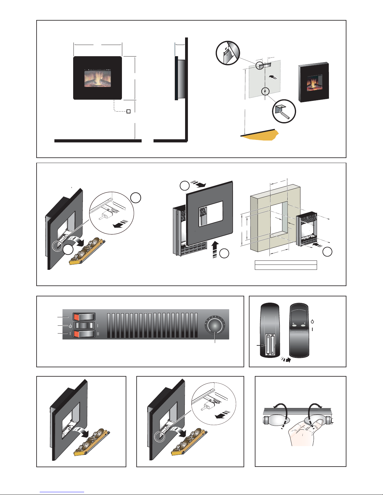
Fig.1
620
300 Min.
600 Recommended
240
1120
Recommended
700
152
Fig.5
Fig.6
Fig.7
Fig.3
A B C D E
410 600 400 424 110
1
4
3
B
C
A
D
E
5
2
Fig.2
1
2
3
M
A
X
T
M
IN
O
F
F
O
N
= Standby
= On
Fig.4
Page 3

Important Safety Advice
When using electrical appliances, basic precautions
should be followed to reduce the risk of fire, electric
shock, and injury to persons, including the following:
If the appliance is damaged, check immediately with the
supplier before installation and operation.
Do not use this heater in the immediate surroundings of
a bath, shower or swimming pool.
Do not use outdoors.
This heater must not be located immediately above or
below a fixed socket outlet or connection box.
Do not cover or obstruct in any way the heat outlet grille
located underneath the heater. Overheating will result if
the heater is accidentally covered.
In the event of a fault unplug the heater.
Unplug the heater when not required for long periods.
The supply cord must be placed on the right hand side
of the heater away from the heat outlet underneath the
heater.
Although this heater complies with safety standards, we
do not recommend its use on deep pile carpets or on
long hair type of rugs.
This appliance is not intended for use by children or
other persons without assistance or supervision if their
physical, sensory or mental capabilities prevent them
from using it safely. Children should be supervised to
ensure that they do not play with the appliance.
The appliance must be positioned so that the plug is
accessible.
If the supply cord is damaged it must be replaced by the
manufacturer or service agent or similarly qualified
person in order to avoid a hazard.
Caution: In order to avoid a hazard due to inadvertent
resetting of the thermal cut-out, this appliance must not
be supplied through an external switching device, such
as a timer, or connected to a circuit that is regularly
switched on and off by the utility.
General
Unpack the heater carefully and retain the packaging for possible
future use, in the event of moving or returning the fire to your
supplier.
The fire incorporates a flame effect, which can be used with or
without heating, so that the comforting effect may be enjoyed at
any time of the year. Using the flame effect on its own only requires
little electricity.
Before connecting the heater check that the supply voltage is
the same as that stated on the heater.
Please note: Used in an environment where background noise
is very low, it may be possible to hear a sound which is related to
the operation of the flame effect. This is normal and should not
be a cause for concern.
Ravello RVO20 Wall Fire
IMPORTANT: THESE INSTRUCTIONS SHOULD BE READ CAREFULLY AND RETAINED FOR FUTURE REFERENCE
Electrical connection
WARNING – THIS APPLIANCE MUST BE EARTHED
This heater must be used on an AC ~ supply only and the voltage
marked on the heater must correspond to the supply voltage.
Before switching on, please read the safety warnings and
operating instructions.
Wall fixing - see Fig. 1
The appliance should be securely fixed to the wall using the wall
plugs and screws supplied for block walls.
Note – for studded walls special fasteners are required, see
diagram for recommended position of fixing screws.
Recessed Installation - see Fig. 2
Please note that this appliance can also be wall-mounted so
that it is recessed. This can be installed in a large fireplace
opening or a purpose built wall. See Table 1 for size of recess
required and hole fixing dimensions.
This fireplace insert does NOT require venting.
In order to ensure its future safety in use, it is essential that this
fire is securely fixed to the wall.
IT IS IMPORTANT THAT THE FIXING DEVICE CHOSEN IS
APPROPRIATE TO THE WALL MATERIAL TO WHICH THE
FIRE IS BEING FIXED. SOME MODERN INTERNAL BUILDING
MATERIALS ARE VERY LOW DENSITY BLOCK AND REQUIRE
SPECIALIZED FIXING DEVICES TO PROVIDE A SAFE,
SECURE INSTALLATION.
The installation of this fire should be carried out by a competent
person. If in doubt please consult your local builder. This section
provides step by step instructions for selecting a location and
preparing the site to install the fireplace into the following:
Existing Fireplace
1. Make sure that the fire is located on a flat surface.
2. Seal all draughts and vents to prevent chimney debris from
falling onto the Fireplace Insert. Do not install into an existing
fireplace that is prone to dampness.
3. Remove the front/trim by following the steps as outlined above.
4. Locate the 4 fixing holes, position the fire accordingly, and
firmly fix the appliance to the wall using the appropriate screws
5. Replace the front/trim.
New Support Structure Construction
When planning where to position your purpose built support
structure the following steps must be observed:
1. Place the fire in the desired location to see how it will look in
the room.
2. Mark the desired location for the new support structure in the
room and store the fire in a safe, dry and dust free location.
3. Using timber studs to support the fire, devise and construct a
suitable means of supporting the product within the wall
partition and provide electrical power for the fire to be HARD
wired. For recommended sizes of height, width and depth of
opening for recess and hole fixing dimensions for each model
4. Remove the front/trim by following the steps as outlined above.
5. Locate the 4 fixing holes, position the fire accordingly, and
firmly fix using the appropriate screws.
6. Replace the front/trim.
NOTE: The appliance should be HARD wired to an electrical
power outlet when placed in a recessed installation. Please
consult a qualified electrician for appropriate wiring requirements.
Where an appliance is Recessed, necessity to allow
disconnection of the appliance from the electrical supply
is required. Incorporate a switch in the fixed wiring in
accordance with the Wiring regulations.
Page 4

Controls - see Fig. 3
The product can be controlled both manually and by remote
control.
Manual Controls
Three switches provide a choice of heat setting. A switch is in
the ON position when the side with the markings on is pushed
in..
Switch 1 Controls the electricity supply to the heater.
Note: This switch must be in the ON position for the heater to
operate with or without heat.
Switch 2 Controls the function of the fire.
Press once to the right give flame effect only.
Press again to give heat and flame effect.
Press again to go back to flame effect only.
Pressing the button in the opposite direction at any
stage turns the fire to standby mode.
Switch 3 Controls the heat output from 1kw to 2kw. The 2kw
output is achieved when in ( II ) position.
Note: To turn fire completely off use Switch 1.
Thermostat - T
In order to maintain a certain room temperature, set the controller
to ‘max.’. Operate the appliance at full power until the required
room temperature is reached. Set back the thermostatic controller
until the appliance switches off. This temperature will be kept
almost constant by the thermostatic control switching on and off
automatically.Please note that the appliance can only be switched
on when the thermostat setting is higher then the room
temperature.
Initializing the Remote Control - see Fig. 4
Note: The remote control is packed separately in the carton.
1. Slide open the battery cover on the back of the remote
transmitter.
2. Install the AAA batteries into the remote control
3. Replace battery cover.
Dispose of batteries in the proper manner according to Provincial
and local regulations. Any battery may leak electrolyte if mixed
with a different battery type, if inserted incorrectly, if all the
batteries are not replaced at the same time, if disposed of in a
fire or if an attempt is made to charge a battery not intended to
be recharged
.
Remote Control Operation
Warning: It takes some time for the receiver to respond to the
transmitter. Do not press the buttons more than once within two
seconds for correct operation. On the control panel, switch 1
must be in the ‘ON’ position in order for the PCB to operate.
Setting
Operation
Flame effect Press ‘I’ button once
Flame effect and heat Press ‘I’ button again
By continuously pressing the ‘I’ button the fire will cycle between
flame effect and flame effect plus heat.
To turn off any of the settings press the ‘
’ button once.
The remote control may be placed, when not in use, in the wallmounted holster provided .
Safety cut-out
For your safety, this appliance has been fitted with thermal cutout. In the event that the product overheats, the cut-out switches
the heat off automatically.
To bring the heat back into operation, remove the cause of the
overheating, then unplug or turn off the electrical supply to the
heater for up to 10 minutes.
When the heater has cooled sufficiently, re-connect and switch
on the heater.
Maintenance
WARNING: ALWAYS DISCONNECT FROM THE POWER
SUPPLY BEFORE ATTEMPTING ANY MAINTENANCE.
Instructions for removing fuel effect
Carefully remove the log effect from the fire by lifting it up and
moving it out. (See Fig.5) Disconnect the 9way connector to
completley detach the logset from the fire (See Fig.6).
Lamp Replacement - see Fig. 7
Warning – Always disconnect from the power supply before
removing lamps.
The lamps reach high temperatures during operation. For this
reason, allow the lamps to cool down after switching off the
appliance. The lamps are located under the fuel effect
Carefully remove the fuel effect from the fire.The defective lamps
should be replaced with a 60W E14 SES clear candle bulb.
UKRU
Cleaning
WARNING – ALWAYS DISCONNECT FROM THE POWER
SUPPLY BEFORE CLEANING THE HEATER.
For general cleaning use a soft clean duster – never use abrasive
cleaners. The glass viewing screen should be cleaned carefully
with a soft cloth. DO NOT use proprietary glass cleaners.
To remove any accumulation of dust or fluff the soft brush
attachment of a vacuum cleaner should occasionally be used to
clean the outlet grille of the fan heater.
Recycling
For electrical products sold within the European
Community.
At the end of the electrical products useful life it
should not be disposed of with household waste.
Please recycle where facilities exist. Check with
your Local Authority or retailer for recycling advice in your country.
After Sales Service
Your product is guaranteed for one year from the date of
purchase.
Within this period, we undertake to repair or exchange this product
free of charge (excluding lamps & subject to availability) provided
it has been installed and operated in accordance with these
instructions.
Your rights under this guarantee are additional to your statutory
rights, which in turn are not affected by this guarantee.
Should you require after sales information or assistance with
this product please go to www.dimplex.co.uk where you will
find our self help guide by clicking on “After Sales” or ring our
helpdesk on 0845 600 5444 (UK) or 01 842 4833 (R.O.I.) .
Spare parts are also available on the website
www.dimplex.co.uk
Please retain your receipt as proof of purchase.
Dimplex UK Ltd.
Millbrook House
Grange Drive
Hedge End
Southampton
Hampshire. SO30 2DF
www.dimplex.co.uk
Republic of Ireland Tel. 01 8424833
[c] Dimplex UK Limited
All rights reserved. Material contained in this publication may not be reproduced in whole or in part, without prior permission in writing of Dimplex UK Limited.
 Loading...