

Page 1
ELECTRICAIRE
WARM AIR HEATING SYSTEM
Models: R7 - 7kW / 46kWh, R8 - 8kW / 57kWh, R10 - 10kW / 69kWh,
R12 - 12kW / 80kWh, R15 - 15kW / 103kWh
INSTALLATION INSTRUCTIONS
IMPORTANT
PLEASE READ THIS LEAFLET CAREFULLY AND RETAIN FOR
FURTHER USE. NOTE ALSO THE INFORMATION GIVEN ON THE HEATER
IMPORTANT - IN EVERY CASE THE UNIT MUST BE FITTED ON
TOP OF A PLENUM CHAMBER FOR CORRECT OPERATION
• The installation must be carried out by trained personnel.
• A means for disconnection must be incorporated in the fi xed wiring in accordance with the wiring rules.
• The heater must not be installed immediately below a socket outlet.
• The heater is not suitable for connectin to a 30A ring circuit.
• Do not position the heater under windows where curtains can contact the heater casing.
• WARNING - THE SURFACES ON THIS HEATER CAN BE HOT.
• This heater meets BS 3456 safety requirements. However, any heater type becomes hot in normal operation. Care
must be taken to ensure that prolonged skin contact with the heater does not occur.
WHERE YOUNG CHILDREN, INFIRM PERSONS, OR THE AGED ARE LIKELY TO BE LEFT UNSUPERVISED
IN THE VICINITY OF THE HEATER WE RECOMMEND THAT A GUARD IS FITTED. Contact your installer or the
manufacturer for further advice.
This appliance is not intended for use by persons (including children) with reduced physical, sensory or mental
capabilities, or lack of experience and knowledge, unless they have been given supervision or instruction concerning
use of the appliance by a person responsible for their safety.
Children should be supervised to ensure that they do not play with the appliance.
• THIS APPLIANCE IS EXTREMELY HEAVY. THE FLOOR MUST BE CHECKED TO ENSURE THAT IT IS CAPABLE
OF BEARING THE WEIGHT OF THE UNIT, UP TO 750KG (¾ TON). DO NOT UNDER ANY CIRCUMSTANCES
ATTEMPT TO MOVE OR REPOSITION THIS HEATER WITHOUT SEEKING EXPERT ADVICE.
• To maintain stability, it is essential that the heater is placed on a level surface.
• The heater must be installed where it is impossible for switches and other controls to be touched by a person using
a bath or shower.
• IMPORTANT - Due to the newness of materials the heater will produce a slight smell for the fi rst few days of
operation. ROOMS MUST BE WELL VENTILATED AND YOUNG CHILDREN, CAGED BIRDS, OR PERSONS
WITH RESPIRATORY COMPLAINTS MUST NOT REMAIN IN CLOSE PROXIMITY TO THE HEATER DURING
THE FIRST 48 HOURS OF THE COMMISSIONING PERIOD.
• IF, DURING ANY REASSEMBLY OF THE HEATER, A PART OF THE THERMAL INSULATION SHOWS DAMAGE
OR DETERIORATION WHICH MAY IMPAIR SAFETY, IT SHOULD BE REPLACED BY AN IDENTICAL PART.
• The heater must stand at least 50mm clear of any walls and 150mm below ceilings.
Page 2

INSTALLATION INSTRUCTIONS
PREPARATION
The heater will arrive separately from its storage
bricks, the following bricks will be required.
R 7 / 8 / 10 - 40 bricks
R12 - 48 bricks
R15 - 64 bricks
Electrical Supply
Two supplies are required for the operation of this heater -
for ‘on-peak’ and ‘off-peak’ supply. Both supplies should be
connected through isolator switches. A time clock / thermostat
control circuit may be required.
WARNING - This appliance
must be earthed
Only heat resisting cable (min. rating T85) should be used.
POSITIONING
Important - In every case the unit must be fi tted on top of a
plenum chamber for correct operation.
The unit can be installed free standing or in a suitable cupboard.
For minimum clearances all around the heater refer to Fig. E. The
fl oor must be checked to ensure that it is capable of bearing the
weight of the unit, see warning on front cover. Also the fl oor should
be fl at and level. A concrete plinth measuring 700x700mm can be
constructed. The plenum should be insulated from the fl oor or plinth
by at least 13mm of non-compressible insulation material.
Page 3
VENTILATION & DUCTING
INSTALLATION
Cupboard Ventilation - When the heater is installed in a cupboard,
two return grilles should be provided in the cupboard door or wall.
The top of the high level grille should be approximately 50mm
below the top of the cupboard and the bottom of the low level grille
approximately 25mm above the plenum top.
Return air grilles should be a minimum of 400mmx250mm. Grilles
must be positioned to return air from the heated areas.
Ducting will be required if the heater is positioned in a cupboard
and also in free standing installations if adjacent rooms are also to
be heated.
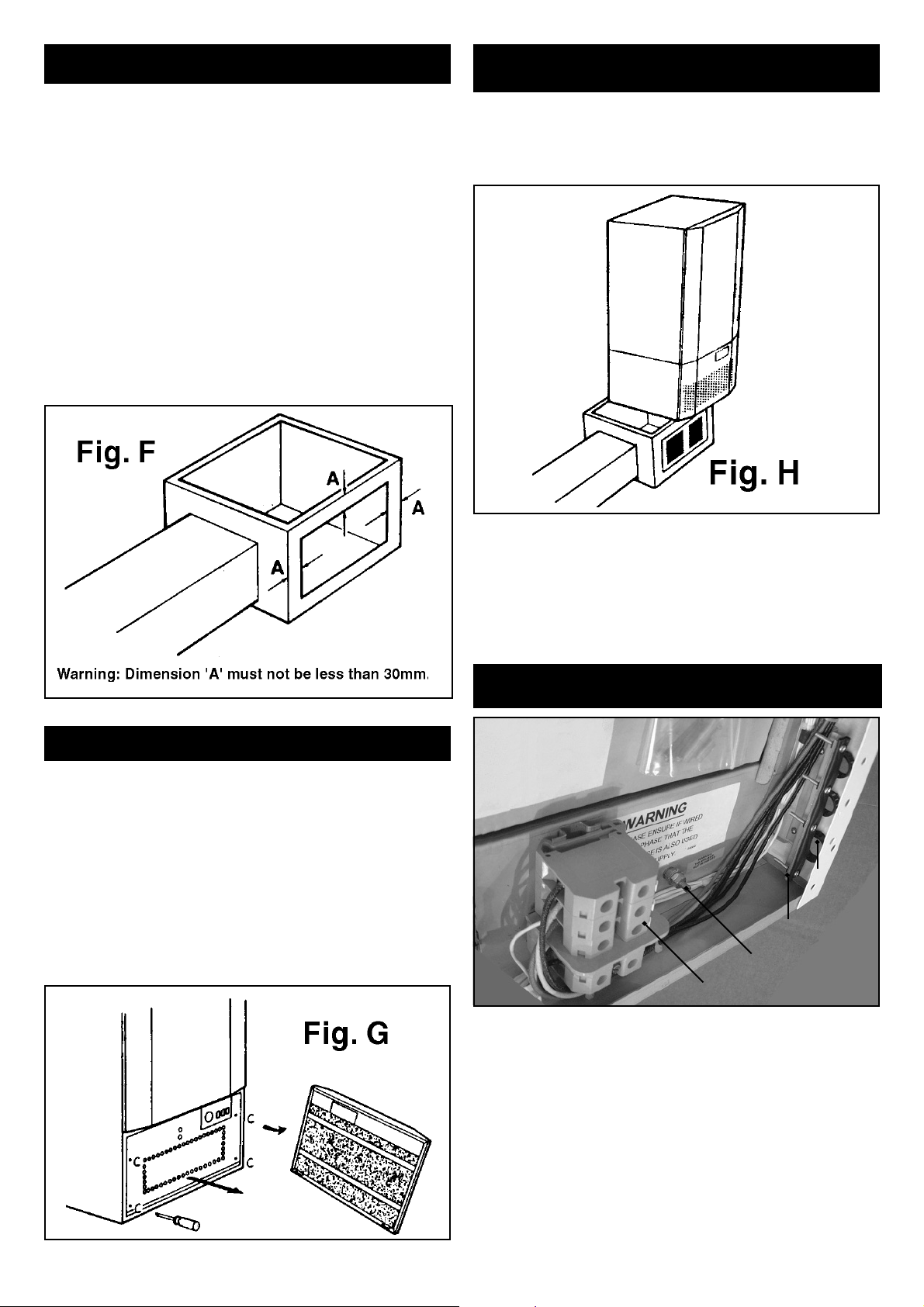
Holes to the required dimensions (to suit airducts used) should be
cut in the sides of the plenum chamber prior to siting. Holes should
not be cut closer than 30mm to either sides, top or bottom of the
plenum - see Fig F. The chamber can then be placed in position.
The ductwork can now be fi rmly attached to the plenum internally,
be means of ‘bent over’ fl anges or externally by pop rivets. Ensure
that all joints are sealed by 50mm wide tape.
1. Lift the heater onto the plenum and work it gently backwards
to its correct location, see Fig. H. Position the heater exactly over
the plenum with sides and rear fl ush to ensure stability. If fi tted in
a cupboard please ensure that the heater is facing the cupboard
door to allow for ease of access.
2. CONNECTION OF THE MAINS CABLE
Cable entry to the unit is at the bottom right hand corner when viewed
from the front. See Fig. I. Conductors are to be fed through bushings
and the clamping bar before being terminated in the terminal blocks
on the lower wiring panel. Several blanking plugs are provided for
any cable entry bushings that are not used.
Important - All mains supplies have to be installed with
independent isolators.
WARNING - This appliance must be earthed
INSPECTION BEFORE INSTALLATION
Having removed the heater from its packing inspect it for possible
damage caused in transit. Note - two sheets of mica insulation will
be found underneath the heater. Retain these in a safe place, see
Section 6. An inspection of the core bricks should also be made
at this stage.
Remove the fi lter panel by pulling the top end away from the heater,
and lift out of location hooks - see Fig G.
Remove the grille mesh by fi rst unscrewing the fi xing screws, then
spring out one end - the grille should now lift clear.
Check that all wiring connections are secure and that the fan rotates
freely.
Fig. I
Bushing
Clamping Bar
Earth
Terminal Block
Main element supplies can be provided from either single phase or
3 phase supplies.
If 3 phase is chosen, the switching circuit must use the red
phase.
An auxiliary or pilot circuit is also required, see Point 3. Control of
the fan operation by a time clock or thermostat is also an option.
Use wiring diagrams for more detail - Figs. A, B and C.
Important
Clarify if the day energy provided by the main heating element is
required. See Point 4.
Carry out the following instructions with care.
Page 4

Main Element Supply - Single Phase
Connect the live (coloured red or brown) of the main supply cable (i.e.
that cable supplying the heating elements) to the D.I.N. connector
block marked ‘L1’ and the neutral lead (coloured blue or black)
to the neutral terminal marked ‘N’. Connect all earth leads (bare
conductors or coloured green or green and yellow) to the earth
terminal marked with the symbol ah. All bare earth conductors must
be sleeved with earth sleeving.
Fit the D.I.N. connector linking bar assembly, see Fig. J, across
D.I.N. connectors marked L1, L2, L3. The linking bar assembly
drops into the centre groove in the top of the connector blocks once
the transit screws, where fi tted, are removed. It is essential that all
screws are fi tted and tightened securely.
Where centre control of the fan is required with the day energy option
the fan supply from the D.I.N. connectors will need to be removed.
Another circuit is required.
Important
Ensure that all cables are routed neatly to the cable clamp, that
no excess wire is left inside the heater and that no wire is left so
that it can ‘foul’ the air mixing fl ap. Tighten the clamp fi rmly on all
incoming cables.
b) Day Energy
The installation design may require the use of the day energy facility
provided by the main heating elements. This facility can be easily
selected using the 8 way snap connectors on the left hand corner
of the lower wiring panel, see Fig. L and Fig. D.
Main Element Supply - Three Phase Connection
Connect each phase of the incoming mains supply cable to the
respective live terminal in the D.I.N. connector blocks i.e. red phase
to L1, yellow phase to L2, blue phase to L3. (Note that the internal
wiring is colour coded red, yellow, blue). Connect the neutral of the
incoming mains supply, coloured black, to the terminal marked ‘N’
on the D.I.N. connector blocks.
Connect all earth leads (bare conductor or coloured green or green
and yellow) to the earth terminal marked with the symbol E. All
bare conductors must be sleeved with earth sleeving.
3. CONNECTION OF AUXILIARY SUPPLY
(FAN OR PILOT)
Connect the live lead of the fan or pilot supply (if day energy is
required, see Point 4), coloured red or brown to the terminal marked
L(u) and likewise the neutral coloured blue or black to the terminal
marked N(u). These terminals are located in the four-way connector
block placed in the centre of the bottom wiring panel. See Fig. K.
and Fig. D
i) Day Energy Operation - If the day energy facility is required the
supply to the mains block will have to be permanently live.
Locate the 8-way connector block and position the two strips so that
the ‘W’s stamped on the strips line up.
ii) Standard Operation - For standard operation position the 8-way
connector so that the ‘S’s stamped on the strips line up.
NOTE: The heater is normally shipped set up for Day Energy
Operation.
5. PREPARATION FOR CORE ASSEMBLY -
i) Remove two screws securing bottom of outer front panel and
lift upwards to withdraw. The ceramic tube for the phial of the
input controller will be taped to a vertical terminal panel - Fig.
M. Remove and keep in a safe place as it will be required when
reassembling the heater - see section 8(e).
Fusible Link
Inner Front
Ceramic Tube
Capillary
of Charge
Controller
4. OPTIONS -
a) Time Clock / Thermostat
Remove the loop of wire from the terminals in the four-way
connector block adjacent to the pilot supply terminal block, see
Fig. K. Remake this connection with the leads from the time clock
and/or thermostat.
Fig. M
ii) Remove the fusible links located halfway up the inner front
panel.
iii) Bend the capillary back to ensure that the inner front panel can
be removed without damaging either capillary or phial.
Page 5

iv) Remove the inner front panel by removing the securing screws.
This panel can now be pulled forward and then withdrawn by tilting
the top outwards and lifting.
v) Note carefully the correct location of the hole in the next layer
of insulation and remove. Check that the interior insulation has not
been disturbed in transit.
vi) Raise the plastic spacers separating the moulded air passages
slightly and remove packs containing elements and sealing strips.
Do not remove spacers until bricks have been built up to same level
as this helps to keep insulation in place - Fig. N.
Ensure both pieces of base insulation have not be disturbed
in transit.
The fi rst layer is constructed from 4 bricks running front to back and
the grooves on top as shown in Fig. S (a). Ensure these sit fi rmly
on the base and locate neatly between the moulded air ducts.
Handle the element with great care. Carefully locate each leg of
the element in a groove of the brick. The second layer can now
be positioned with the brick running from side to side as layer b.
(Except R15 Models - see Fig. T).
Refer to the table and sketch - see Fig. T and fi t the brick exactly as
shown. Element positions are indicated by the numbers.
IMPORTANT - Mica insulation sheets are provided to insulate
between phases. These must be fi tted between the brick layers at
the points indicated on the diagram. Additional labels are also fi tted
to the terminal panels of the heater.
Fig. N
Sealing
Strips
Box
containing
Elements
Spacers
7. CONNECTING THE ELEMENTS
It is important that no part of the bare element wire is exposed or is
close to the brick. The elements are insulated with porcelain fi sh-
spine beads and can be pushed over the wire to ensure there are no
gaps. Locate each element tail in the appropriate groove and route it
round against the side and thread it through the ceramic bush in the
vertical terminal panel. Connect the end of the tail to the appropriate
terminal block. See Fig. O. Note: there is a maximum of two element
tails per terminal block. Check the wiring at this stage for electrical
continuity and insulation resistance. To ensure that the elements are
correctly tightened into the terminal block it is imperative to tighten
it again. This should be done at least three times.
Fig. O
Ensure base
insulation has
not moved during
transit.
Do not cover air inlet
and outlet holes.
vii) Inspect each element and the charge controller for damage
during transit.
6. CORE ASSEMBLY - see Fig. T
NOTE: It is essential that the thermal insulation, especially
the moulded air passages, are not damaged during assembly.
Follow these instructions carefully.
Care must be taken to ensure that the bricks, when fi tted, do not
intrude into the space allowed for air passages around the core. Air
inlet and outlet holes in the bottom of the core must not be covered.
Avoid excess gaps in the core by placing the bricks as close as
possible during assembly.
Follow the instructions below and refer to Fig. T to ensure safe
installation.
Each layer uses 4 double sized bricks. Build the core a layer at a
time and include the elements at the appropriate position as shown
by the number indicated in Fig. T.
Page 6

8. REASSEMBLY OF THE UNIT
i) Fit side insulation strips on each side between the cold tails and
the inner front panel - Fig. P.
ii) Replace inner front insulation. Ensure that when insulation is
fi tted the hole for the charge controller lines up with the grooves in
the second and third layer of bricks down from
the top. In the R15/104 unit only, the charge
controller is entered in grooves between the
fourth and fi fth layers from the top - Fig. Q
Fig.P
Sealing
Strip
Fig. Q
Inner Front
Insulation
iii) Replace inner front panel and secure with screws. Ensure that
hole for charge controller in this panel lines up with that in the inner
front insulation.
iv) Reconnect the fusible links and check for electrical continuity.
Ensure that the fusible links fi t properly into the support bracket.
v) A special ceramic tube houses the phial of the input controller.
Fit the ceramic tube by inserting it through the hole in the safe door
pushing it in the full length - Fig. R.
vi) Fit the input controller phial into the ceramic tube until the end
of the phial bottoms in the tube. About 150mm of the capillary also
goes into this tube. Secure the remainder of the capillary to the
safe door using the clips provided.
9. COMMISSIONING THE UNIT
When the heater has been completely assembled it will be necessary
to commission the unit. This entails checking that the unit is functioning
properly, that the airfl ow delivered is correct for the installation and
that the outlet air temperatures are acceptable.
Fan speeds and outlet temperatures are factory preset but the fan
speed can be adjusted by following the points below;
i) Switch on the heater with the charge controller set at Max and
allow to charge up overnight.
ii) Switch ‘on’ the fan at ‘Boost’ speed and run for fi fteen minutes.
iii) Check the airfl ow delivered and if incorrect adjust as follows;
Switch off mains supplies (both restricted and unrestricted).
Remove fi lter panel. Remove grille. Loosen the fi rst moveable
band from the left on the fan speed resistor (see Fig. D) and move
towards the left-hand end to increase the fan speed, towards the
right-hand end to decrease the fan speed. Tighten up the band on
the resistor and reassemble the heater. Switch on and check the
airfl ow. Repeat the adjustment if necessary.
iv) Switch the fan on to normal speed. After 15 minutes check the
airfl ow delivered, if it is incorrect adjust as above, but in this case it
is the second moveable band from the left which alters the speed.
Ceramic Phial
Holder
Clip
Capillary
Tube
Fig. R
vii) Replace the outer front panel.
viii) Replace the grille mesh.
ix) Replace the fi lter panel.
IMPORTANT - Recheck all electrical connections
for tightness.
Page 7

SPECIAL INSTRUCTIONS FOR CONVERSION FROM R10 TO R7 / R8 HEATER
Follow these instructions carefully to ensure the Electricaire units operate safely and reliably.
The build of the storage core for models R7, R8 and R10 is identical (see diagram Model No. R7/8/10). Elements must only be fi tted
as indicated below.
MODEL R7
Only four elements must be used for this specifi cation. Install elements in positions 3, 4, 5 and 6 only. See diagram Model No.
R7/8/10.
MODEL R8
Only fi ve elements are to be used for this specifi cation. Fit elements into positions 2, 3, 4, 5 and 6 only. See diagram Model No.
R7/8/10.
MODEL R10
All 6 elements are installed as per diagram Model No. R7/8/10.
Important
Self adhesive rating labels are supplied. Please ensure the correct rating label, identifying the correct model,
is fi tted. The rating label is fi xed to the mesh panel behind the detachable fi lter.
Page 8

Installer Note: Please ensure that the USER INSTRUCTIONS are handed
to the User when you have completed the installation if applicable, or left with the
heater if the building is unoccupied when the installation is carried out.
RECYCLING
For electrical products sold within the European Community. At the end of the electrical products useful life
it should not be disposed of with household waste. Please recycle where facilities exist. Check with your Local
Authority or retailer for recycling advice in your country.
ELECTRICAIRE
Customer Help Line 0845 600 5111
Mon–Thurs 08.30-17.00 and Fri 08.30-16.00 (Sept-April)
Mon–Thurs 08.30-17.00 and Fri 08.30-15.00 (May to August)
Fax 01489 773 050
Web-site www.dimplex.co.uk
e-mail technical.services@dimplex.co.uk
Republic of Ireland 01 842 4833
Dimplex UK Ltd,
Millbrook House,
Grange Drive,
Hedge End,
Southampton,
Hampshire,
SO30 2DF
© Dimplex UK Limited
All rights reserved. Material contained in this publication may not be reproduced in whole or part, without prior permission in writing from Dimplex UK Limited.
71186 Issue 8 : 02.09
 Loading...