

Page 1
Fan Forced Wall Heater
R23SH/R23DH/T23WH Series
IMPORTANT INSTRUCTIONS
When using electrical appliances, basic precautions should al-
ways be followed to reduce the risk of re, electric shock, and
injury to persons, including the following:
1. Read all instructions before using the heater.
2. The heater is hot when in use. To avoid burns, do not let
bare skin touch hot surfaces. The trim around the heater
outlet becomes hot during heater operation. Keep combustible materials, such as furniture, pillows, bedding, papers, clothes, and curtains at least 3 ft (0.9 m) from the
front of the unit and keep them away from the sides and
rear.
3. Extreme caution is necessary when any heater is used by
or near children or invalids and whenever the unit is left
operating and unattended.
4. Do not operate any heater after it malfunctions. Disconnect power at the service panel and have the heater inspected by a reputable electrician before reusing.
5. Do not use outdoors.
6. To disconnect the unit, turn the controls off, and then
switch off at main power supply panel.
7. Do not insert or allow foreign objects to enter any ventilation or exhaust opening as this may cause an electric
shock or re, or damage to the heater.
8. To prevent a possible re, do not block air intake or ex-
haust in any manner.
9. All electrical heaters have hot and arcing or sparking parts
inside. Do not use in areas where gasoline, paint, or ammable liquids are used or stored.
10. Do not modify this heater. Use it only as described in this
manual. Any other use not recommended by the manufac-
turer may cause re, electric shock or injury to persons.
SAVE THESE INSTRUCTIONS
Installation Instructions
WARNING: To reduce the risk of re, do not store or use
gasoline or other ammable vapors or liquids in the vicinity of
the heater.
CAUTION: High temperature, risk of re, keep electrical
cords, drapery, furnishings, and other combustibles at least 3
feet (0.9 m) from the front of the heater.
This heater is designed for permanent installation only. Care
should be taken to install according to the following instructions. All required clearances should be maintained. In addition all electrical wiring and connections should comply with
local electrical codes.
!
NOTE: It is extremely important to read all information labels. Care must be taken to ensure that the heater is rated the
same voltage as the electrical supply wires. Failure to do so
could result in unsafe heater operation as well as damage to the
unit. If replacing an existing heater, check the labels of the old
heater to ensure the voltage of the new heater is compatible.
Figure 1
Figure 2
!
All units should be controlled by means of a regulating thermostat. Certain models only are provided with built in thermostats. Check the Model Key Information section for veri-
cation. Wall thermostats should comply with the voltage and
wattage of all heaters on the circuit.
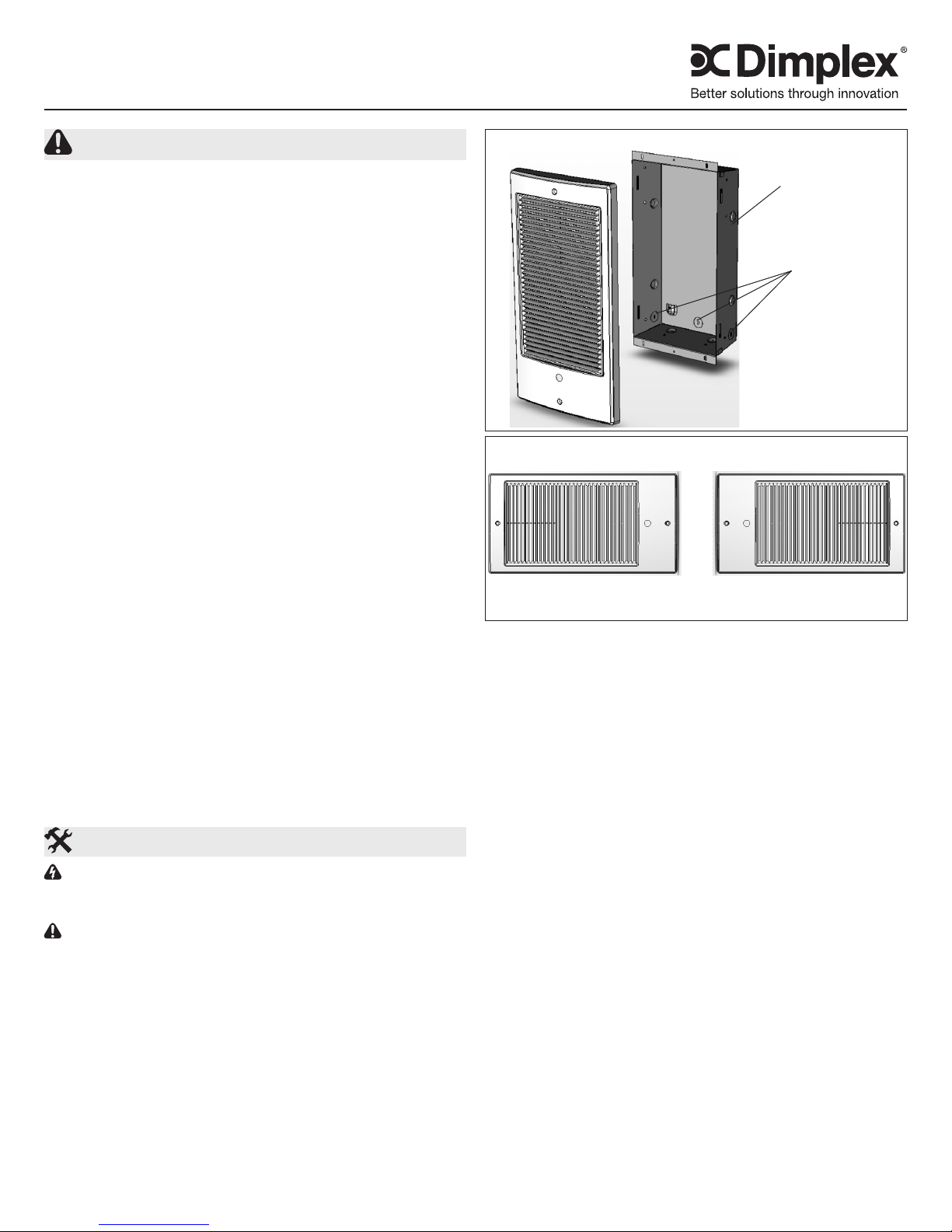
All installations require the following components:
1) Recess Box (Model 1011650100)
2) Heater Assembly (See nameplate Label)
3) Grille
An optional Surface Mount Box is available for installations
that are not recessed in wall cavity.
Step 1 – Placement
All units are designed for placement in either interior or exterior walls. Care should be taken to provide a minimum of
8" clearance from oors, ceilings and adjacent walls. Once
installed, the airow through the heater should not be blocked
in any way. Maintain 3’ (91.4cm) clearance of objects from the
front of unit. Maintain a spacing of 3’ (91.4cm) between heaters in order to prevent re-circulation of heated air. Insulation
surrounding the back and sides of the recess mount box will
not affect performance. Ensure insulation is rated for temperatures up to 185°F (85°C).
!
NOTE: Certain ooring and wall covering materials (par-
ticularly those incorporating clear vinyl materials tend to distort
at temperatures in the vicinity of 140°F (60°C). Material shall
be checked prior to installation to determine if discoloration
will occur. Units are not approved for placement in oors or
ceilings. Do not install in any area where combustible vapors,
Multi-Directional Grille Orientation
Recess Box
Wiring Access
Alternate Multi-Directional Grille Orientation
NOTE: Maintain a minimum clearance of 8” from adjacent
walls, oors and ceilings on all four sides of the grille
7207160100R09
Page 2
gases, dusts or liquids are present. Fire or explosion may occur.
Step 2 – Mounting The Recess Box
Determine the desired orientation of unit. Provide an opening
in wall 14 ¼” x 8 1/8" x 3" (36.2cm x 20.6cm x 7.6cm) deep,
minimum. Care should be taken to install the recess box in the
correct orientation to accommodate grille. Note the position
of the electrical entry knockouts and orient recess box
according to Figure 1. Ensure all required clearances are
met.
Ensure recess box anges are ush with the nished wall
surface. For new construction, the sides of the recess box
are marked with guidelines to allow for ½” (1.3cm) and 5/8“
(1.6cm) drywall thickness if drywall is to be added at a later
date. Secure recess box to studs with screws using holes pro-
vided on sides or ange of recess box. Remove appropriate
electrical knockout and secure supply wire using an approved
strain relief connector leaving 6” (15.2cm) of wire leads in the
recess box.
Step 3 - Mounting the Heater Assembly
Insert the heater assembly into the recess box ensuring that
the tab on the heater assembly slides into the slot in the recess box. Ensure the heater assembly is fully seated and secure to the recess box using the captive screw provided.
Be careful not to handle the heater where the cutout is located.
Step 4 –Electrical Connections
WARNING: Hazard of severe shock.
CAUTION: Disconnect all power coming to heater at main
service panel before wiring or servicing.
Turn off power supply at the electrical panel. Route supply
wires from circuit breaker through wall thermostat to heater.
For models with built in thermostat route from circuit breaker
to heater.
Supply wire must be of two wire plus ground variety, with a
rating capable of handling all loads on the circuit. Supply wire
should be rated for a minimum of 140°F (60°C). Make electrical connection according to relevant wiring diagrams. Make
connections using approved wire nut connectors and secure
the grounding wire to the ground screw on the heater chassis.
Step 5 – Secure the Front Panel
If your unit has a built in thermostat remove the plug on the
front panel. Fasten the Front Grille using the screws provided.
It is important to note that the front grille is oriented in the
required positions shown in Figure 1 and on the Multi – Directional grille. For units with built in thermostat push knob onto
thermostat shaft through plug hole.
Operation and Maintenance
WARNING: This heater must be properly installed before it
is used.
WARNING: Disconnect power and heater has cooled be-
fore attempting any maintenance or cleaning to reduce the
risk of re, electric shock or damage to persons.
!
NOTE: This heater should not be operated with an accumulation of dust or dirt on or in the unit, as this can cause
a build up of heat and eventual damage. For this reason the
heater must be inspected regularly, depending upon conditions and at least at yearly intervals.
For units with built in thermostats, rotate the thermostat knob
fully clockwise. Heater should activate. When the room reaches the desired temperature, slowly rotate the knob counterclockwise until unit shuts off. The heater will automatically
cycle around this preset temperature setting.
All units contain a Manual Reset High Temperature Cutout,
which will shut the heater off in the event of abnormally high
operating temperatures. The high temperature cutout can be
reset by switching the main power off and waiting ve minutes before switching it to back on. In addition a Red Warning Light will activate providing a visual warning. If this condition exists, disconnect all power to the unit and call a licensed
electrician for service. Do not use heater until the problem is
determined and corrected. ENSURE POWER TO THE UNIT
IS DISCONNECTED PRIOR TO SERVICING OR PERFORMING CLEANING.
Warranty
The Manufacturer warrants the heater and components of the enclosed product against any defect in material or workmanship for a
period of two years from the date of purchase, with the exception of
the elements which are warranted to be free from defect in material and workmanship for ten years. In full satisfaction of any claims
under this Warranty the Manufacturer will repair or replace without
charge, in its factory or in the eld as it alone may decide, any parts
which in its opinion are defective.
The Manufacturer shall not be responsible for any transportation or
shipping costs in relation to such repair or replacement except as
specically assumed by it. Misuse of this product or repairs by persons other than the Manufacturer’s authorized personnel without the
Manufacturer’s written approval, will void this Warranty.
This Warranty is in lieu of all other warranties or conditions whether
expressed or implied including but not limited to those of merchant-
ability or tness for purpose and shall constitute the sole remedy of
the Purchaser and the sole liability of the Manufacturer in respect of
the sale of the product, whether in the nature of breach or breach of
fundamental term, or of negligence or otherwise.
The Manufacturer shall not be liable for any special, indirect or consequential damages or for any damages resulting from removal or
replacement of a small wall heater subject to warranty claim without
the Manufacturer’s authorization.
This Warranty is transferable by the original consumer purchaser of
the product. Any claims under this Warranty must be submitted in
writing to the Service Manager, Dimplex North America Ltd., 1367
Industrial Rd., Cambridge, Ontario N1R 7G8, Canada.
www.dimplex.com2
Page 3

Model Key Information
PRODUCT LEGEND: X YY WW VV B T C Z
X YY WW VV B T C Z
R23 RETAIL SH SINGLE ELEMENT 05 500 07 240 B BULK PACKAGING T THERMOSTAT C WALL CAN W WHITE
T23 COMMERCIAL TRADE DH DOUBLE ELEMENT 07 750 10 240 A ALMOND
WH SINGLE ELEMENT 10 1000 11 120
12 1250 21 208
15 1500 31 240/208
20 2000
R23SH & T23WH Models Wiring Diagram
Basic Heater Field Connection
High Limit
Motor
!
Element
(120V Marked N)
NOTE: All units rated for 240/208 V provide 76% wattage of
Black
L1
Ground
White: 120V
Black: 240V/208V
240V rating when connected to 208 V.
Replacement Parts
Single Element Part Numbers
120V 208V 240V or 240V/208V
500W
750W
1000W
1250W
1500W
2000W
Double Element
Grille
Motors
Fan Blade ...............................5300130100RP
High Limit Cutout ........................2300330100RP
Recess Mount Box ............................T23WHC
Accessories
2200520100RP N/A 2200520700RP
2200520200RP N/A 2200520800RP
2200520300RP N/A 2200520900RP
2200521200RP 2200521300RP 2200521400RP
2200520400RP N/A 2200521000RP
2200520500RP 2200520600RP 2200521100RP
240/208V 2000/1500W .................2200540900RP
240/208V 1500/1125W .................2200540800RP
Multi - Directional Grille - Almond ...............T23WHA
Multi - Directional Grille - White ................T23WHW
120V models ..........................2000280300RP
208V models ..........................2000280200RP
240/208V models ......................2000280100RP
Single Pole Thermostat Kit .....................TWHT1
Double Pole Thermostat Kit .................... TWHT2
Surface Mount Box - Almond ..................TWHSBA
Surface Mount Box - White .................... TWHSBW
R23DH Models (Double element) Wiring Diagram
High Limit
Motor
!
Element
NOTE: For reduced heat output do not connect wire C to 240 V
Thermostat
Blue
Red
Black
240 Volt
Line (L1)
Optional *
240 Volt
Line (L2)
line (L2). Wire C must be capped off using a wire nut supplied by
the customer when not used.
Cat. No. Volts Wattage Connections
R23DH2010 240 2000W L1-A, L2-B & C
1000W L1-A, L2-B ONLY*
R23DH1507 240 1500W L1-A, L2-B & C
750W L1-A, L2-B ONLY*
Optional
Surface Box
Recess Box
Heater Assembly
Multi-Directional Grille
1367 Industrial Road Cambridge ON Canada N1R 7G8
1-888-346-7539 www.dimplex.com
In keeping with our policy of continuous product improvement, we reserve the right to make changes without notice.
© 2014 Dimplex North America Limited
 Loading...