

Dimplex QSH-70, QSH-100, QSH-125, QSH-150 Owner's Manual
Owner’s Manual
Quantum Storage Heater
Models:
Boost Output
208/240V~
Rated Input
208/240V~
Rated Output for 8hr
Charge Period
# of Bricks
(3 Bricks per Package)
Installed Weight
kWh 10.9 kWh 15.4 kWh 19.3 kWh 23.1 kWh
IMPORTANT SAFETY INFORMATION: Always read this manual rst before attempting to install or use this
Heating System. For your safety, always comply with all warnings and safety instructions contained in this
manual to prevent personal injury or property damage.
To view the full line of Dimplex products, please visit www.dimplex.com
QSH-70 QSH-100 QSH-125 QSH-150
473/630W 660/880W 848/1130W 1035/1380W
1170/1560W 1665/2220W 2070/2760W 2478/3300W
700W 1000W 1250W 1500W
18 24 30 36
91 kg
(200 lbs)
115 kg
(254 lbs)
142 kg
(313 lbs)
165 kg
(364 lbs)
7212670100R02
Table of Contents
Welcome & Congratulations ........................................................3
IMPORTANT INSTRUCTIONS ......................................................4
Quick Reference Guide ............................................................5
General Introduction ..............................................................5
The Benets of Quantum ..........................................................5
Choosing a Location ..............................................................5
Site Selection and Preparation ......................................................6
Installation Instructions ............................................................7
Electrical Connections ............................................................7
Building the Center Core ..........................................................8
Reassembly ....................................................................9
Operation ......................................................................10
Controls ......................................................................10
Control Functions ...............................................................10
Setting the Date and Time ........................................................11
Choosing and Setting a Timer Mode ................................................11
Options .......................................................................12
Child Lock .....................................................................12
User Information ................................................................13
Service Menu ..................................................................13
Maintenance ...................................................................13
Cleaning ......................................................................13
Warranty .....................................................................14
Always use a qualied technician or service
agency to repair this system.
!
NOTE: Procedures and techniques that are
considered important enough to emphasize.
CAUTION: Procedures and techniques which,
if not carefully followed, will result in damage to
the equipment.
WARNING: Procedures and techniques which,
if not carefully followed, will expose the user to
the risk of re, serious injury, or death.
2 www.renewables.dimplex.com
Welcome & Congratulations
Thank you and congratulations for choosing to purchase a Quantum Storage Heating
System from Dimplex.
Please carefully read and save these instructions.
CAUTION: Read all instructions and warnings carefully before starting installation.
Failure to follow these instructions may result in a possible electric shock, re hazard and
will void the warranty.
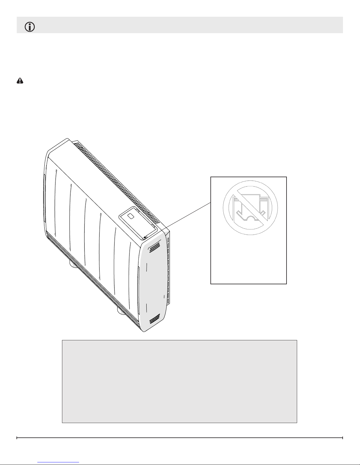
Please record your model and serial numbers below for future reference: model and serial numbers can be found on the Model and Serial Number Label of your heater.
DO NOT COVER
Model:
Serial:
Series:
Questions with operation or assembly? Require Parts Information?
Product Under Manufacturer’s Warranty?
Contact us at: www.renewables.dimplex.com/contact_us
For Troubleshooting and Technical Support
OR Toll-Free 1-888-DIMPLEX (1-888-346-7539)
Monday to Friday 8:00 a.m. to 4:30 p.m. EST
Please have your model number and product serial number ready. (See above)
3

IMPORTANT INSTRUCTIONS
When using electrical appliances, basic precautions should always be followed to reduce the risk of re, electric
shock and injury to person, including the following:
1. Read all instructions before using this heater.
2. Heater and controls should be installed by a qualied contractor. Wiring procedures and connections should
be in accordance with the National Electric Code (CEC & NEC) and local codes.
3. A heater has hot and arcing or sparking parts inside. Do not use it in areas where gasoline, paint or ammable
liquids are used or stored.
4. This heater is hot when in use. To avoid burns, do not let bare skin touch hot surfaces. Keep combustible materials such as: furniture, pillows, bedding, papers, clothes and curtains away from heater.
5. To prevent a possible re, do not block air intakes or exhaust in any manner. Do not use on soft surfaces like a
bed where openings may become blocked.
6. Do not insert or allow foreign objects to enter any ventilation or exhaust opening as this may cause an electric
shock or re, or damage the heater.
7. Do not install these heaters against combustible, low density cellulose bre surfaces or vinyl wall paper.
8. Do not locate these heaters below any electrical convenience receptacles.
9. Quantum heater are not suitable for installation in bathrooms or areas of high humidity.
10. Check nameplate ratings to be sure the heater voltage is the same as the service supply.
11. HIGH TEMPERATURES: Keep electrical cords, furniture, draperies or any other blocking material away from
the heater. See Installation Section for specic distances.
12. The heater is very heavy and must be secured to a wall to ensure that it cannot move.
SAVE THESE INSTRUCTIONS
4 www.renewables.dimplex.com
Quick Reference Guide
General Introduction
This storage heater heats its highly insulated storage core of dense ceramic material at preselected
times to meet the day’s heating requirements.
When heat is required throughout the day, the
heater releases its stored heat by a silent thermostatically controlled fan. The Dimplex control
system automatically stores more energy as it
gets colder, keeping you warm and comfortable
no matter the outdoor conditions. Additional boost
elements are incorporated to ensure consistent
comfort if the core ever runs low on energy.
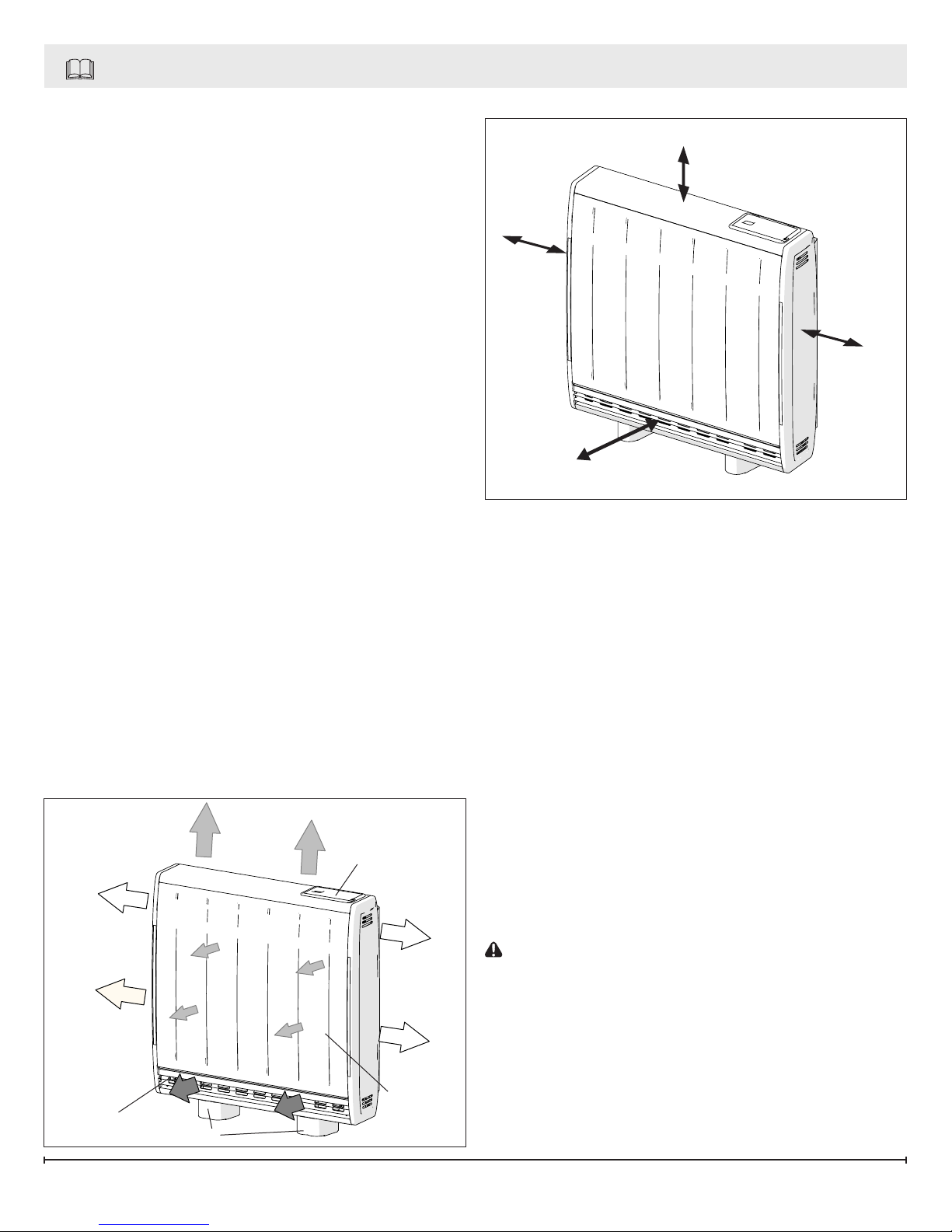
The Benets of Quantum
Quantum is designed to be a responsive heating
system that meets your comfort requirements while
optimizing energy use. The heater releases heat
in two ways:
• A small amount of heat is dispersed by ‘natural’ convection and radiation from the heater
case.
• The vast majority of heat is released using the
built-in fan that pushes hot air out from the
heat outlet grille at the bottom of the product.
Minimizing the release of stored heat from the
outer casing means that more energy is available
when warmth is required. This makes more efcient use of the stored energy as you can ‘turn off’
the heater when you are out or do not need it.
Figure 1
Controls
Figure 2
250 mm (9.8”)
100 mm
(3.9”)
100 mm
(3.9”)
300 mm (11.8”)
Choosing a Location
Compared with traditional storage heaters the
amount of energy released from the outer case
of the heater is signicantly reduced. This allows
more efcient running because the Quantum is
heating the room only when you want it to.
!
NOTE: Occasional clicking sounds during
operation are due to temperature changes in the
storage core.
When determining a location for the Quantum Storage Heater ensure that no objects are closer than
300 mm (11.8”) in front of the unit, 100 mm (3.9”)
on either side or 250 mm (9.8”) above the heater.
(Figure 2)
!
NOTE: The new material in the heater will pro-
duce a slight smell for the rst few days of operation.
Heat Outlet
Feet
Front
Panel
CAUTION: Rooms must be well ventilated and
your children, cages birds, or persons with respiratory complaints must not remain in close proximity
to the heater during the rst 48 hours of the startup period of each heater.
!
NOTE: During rst operation of the fan you may
notice a small amount of dust discharged from the
air outlet grille at the bottom of the product.
5
Site Selection and Preparation
1. Place the heater at on the ground with arrows
printed on the base of the carton pointing
upwards. Open the carton at the bottom,
slide the heater out of the carton exposing the
feet and the hardware kit located within the
packaging on the right hand side. Remove the
feet and the hardware kit.
2. Secure the feet to the heater, using the screws
provided in the hardware kit.
!
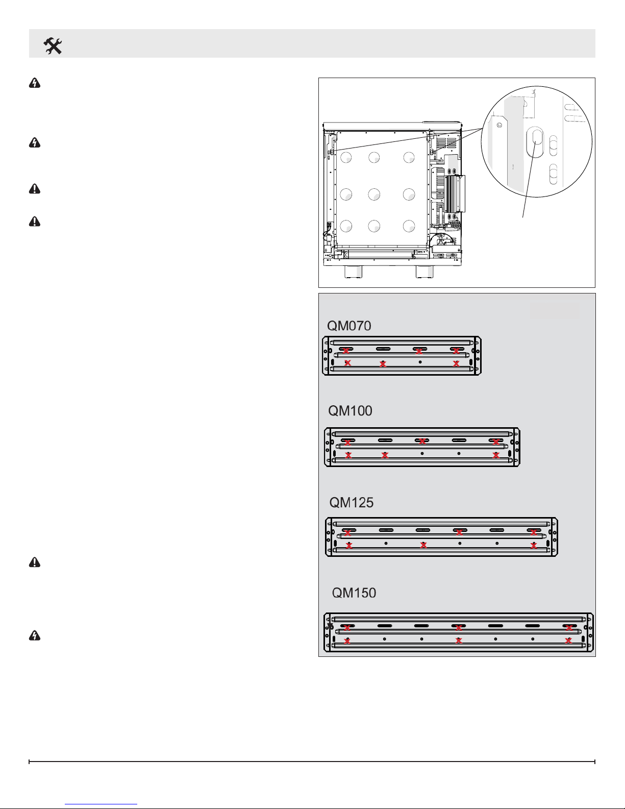
NOTE: For models QSH-70 and QSH-100
two locations are possible for mounting each
foot. They are indicated by an “X” and “Y”
marking visible on the base of the heater.
3. Ensure the feet are secured at the location
holes marked with an “X”, see Figure 3.
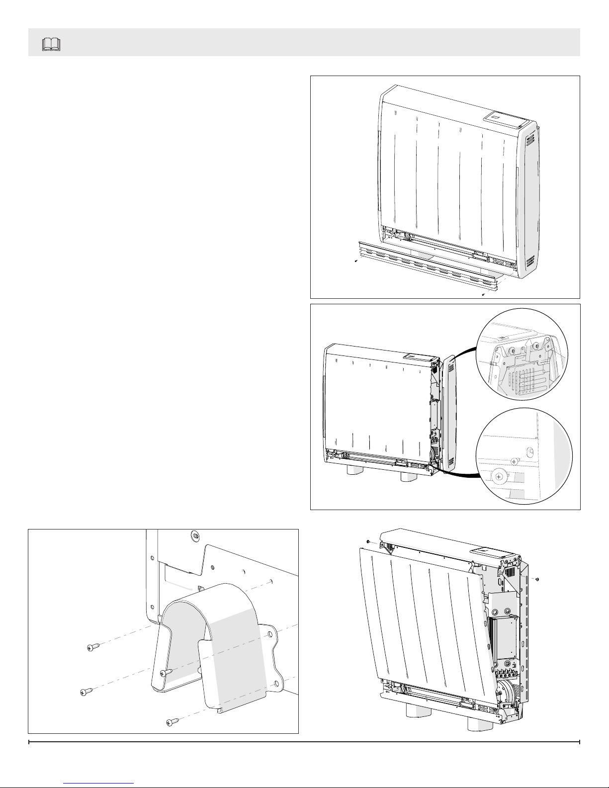
4. Stand the heater on its feet before removing
the packaging.
5. Once the feet have been secured and the unit
has been turned upright, remove the grille from
the side of the unit. (Figure 4)
Figure 4
Figure 5
B
6. Remove the two screws located towards the
bottom at each end of the heater, which retain
the heater sides. (Figure 5A)
7. Push the end panels vertically upwards to
release each side from its securing points.
(Figure 5B)
8. Remove the two screws securing the front
panel, located at the upper sides of the heater,
and swing the upper edge of the front panel
forwards and unhook it from along the heater
base. (Figure 6)
Figure 3
A
Figure 6
6 www.renewables.dimplex.com
Installation Instructions
WARNING: This appliance is heavy. The oor
must be checked to ensure that it is capable of
bearing the weight of the unit up to 177 kg (390
lbs).
WARNING: Do not under any circumstances
attempt to move or reposition this heater
without seeking expert advice.
CAUTION: The heater must be securely xed
to a wall before operation.
CAUTION: Do not install the unit on carpet or
any other soft surface. If installing in a carpeted
area remove the carpet and underlay so that the
feet rest directly on the oor. Ensure that the unit
is level.
1. Place the heater in its nal position and mark
the xing holes through the location holes
visible through the back of the heater.
Mark the xing positions at the two extreme
ends of the heater with the heater pushed tight
against the wall.
Remove the wall bracket from the heater by
removing the two screws at each end of the
bracket. Place the heater to one side and
position the bracket against the wall aligning it
with the location marks.
2. Six screw locations, on the bracket, must be
selected for each model. Mark the positions for
the screw holes. Remove the bracket from the
wall, drill the holes and mount the bracket using
the appropriate hardware for that particular type
of wall.
3. Secure the heater to the bracket using the
screws previously removed.
CAUTION: Under no circumstances should
these screws be removed without rst removing all
bricks from the heater.
Figure 7
Mounting Holes
Figure 8
Electrical Connections
WARNING: The installation of this appliance
should be carried out by a competent
electrician and be in accordance with National
Electrical Codes (NEC) and local codes.
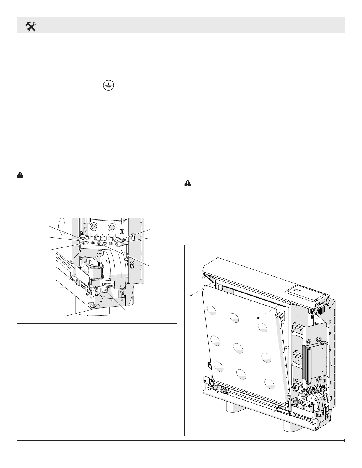
1. The heater is factory congured to operate with
one main power supply.
2. Storage/Fan Circuit:
• Ensure the black wire is connected to the
7
Installation Instructions
terminal marked L1.
• Ensure the red wire is connected to the
terminal marked L2.
• The ground wire should be connected to the
terminal marked E or .
!
NOTE: For 208V installations the wiring must be
modied for the motor to operate correctly.
• 208V installations ONLY: Disconnect one end
of the the blue wire on T6 and connect it to T5.
3. The main power entry clamp and terminal block
will be visible on the right hand side of the unit.
Insert the power cables through the opening at
the bottom of the heater and connect. (Figure
9)
CAUTION: Only heat resistant wiring should be
used, capable of withstanding temperatures up to
90°C (194°F).
Figure 9
208/240V Installations
Terminal
Block
L
2
T5
T6
Building the Center Core
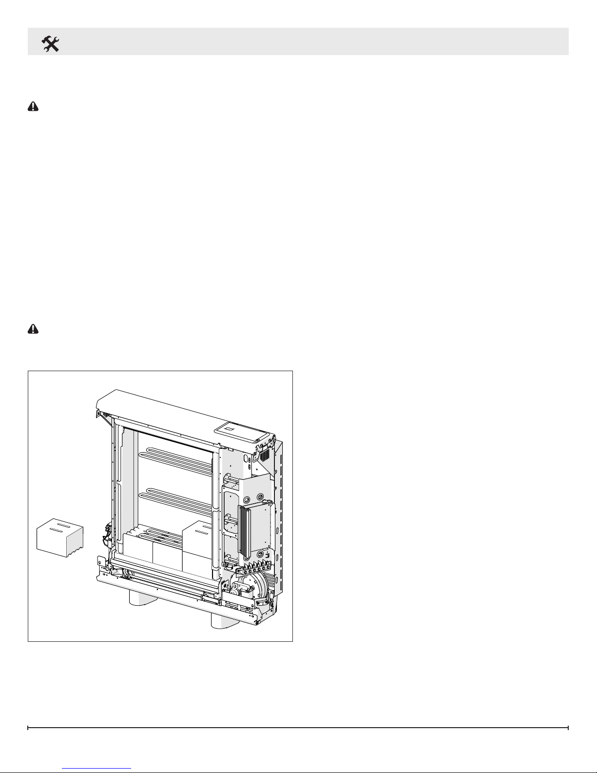
1. Remove the inner panel to access the core of
the heater. Lay the inner panel carefully to one
side to ensure it is not damaged. (Figure 10)
2. Remove any internal packaging.
3. The bricks have several grooves on one
surface for locating around the elements. The
two slots through the centre of the brick create
the air passages within the core.
4. Position the rst brick of the bottom row to the
right rmly pressed against the side insulation
with the element grooves facing upwards and
tting neatly around the element. Angle the
element upward to t the brick and the air
passages line up with the holes in the base
insulation.
CAUTION: Do not disconnect the element
terminals
5. Fit the remaining bricks in the bottom row being
careful not to damage or dislodge the element.
6. Position the second row of bricks so that they
are facing down and the element sits within the
grooves. (Figure 11)
L
1
Wire Entrance
Figure 10
G
Cable Clamp
8 www.renewables.dimplex.com
Installation Instructions
7. The third row of brick is positioned in a manner
similar to the rst row.
CAUTION: Be careful not to damage or
dislodge the element.
8. Repeat the pattern for the remaining rows.
9. Check that all the bricks are secure and evenly
located.
10. Close the core by replacing the inner panel
complete with insulation.
11. Ensure the bottom edge is located inside the
chassis and that the screws are tightly secured
at each edge.
!
NOTE: Double check all wiring connections
are secure and any excess cable is restrained
and cannot come in contact with any of the
heater casing. Under no circumstances should
any excess cable be pushed inside or behind the
heater.
CAUTION: Once installed do not attempt to
reposition the heater without rst unloading the
bricks.
Reassembly
1. Replace all the panels of the outer casing
reverse steps 5-8 of Site Selection and
Preparation Section.
2. Ensure all of the hardware has been tightened.
3. Clean the outlet grille and adjacent surfaces
after the rst operation as some dust may be
produced when the heater is rst used.
In cases where unauthorized persons may tamper with the control settings it is possible to set a
tamper-proof feature at the time of installation, by
pressing and holding the Back button and the Selector Dial simultaneously for three seconds, ‘Child
Lock’ will appear on the screen, repeat to reverse.
See the Operating Instructions for further details.
Figure 11
9
 Loading...