

Page 1
Montage- und
Gebrauchsanweisung
Installation and
Operating Instruction
Instruction d‘installation
et d‘utilisation
Bestell-Nr. / Order no. / No de commande : PSP 1000K DE / EN / FR · FD 9802
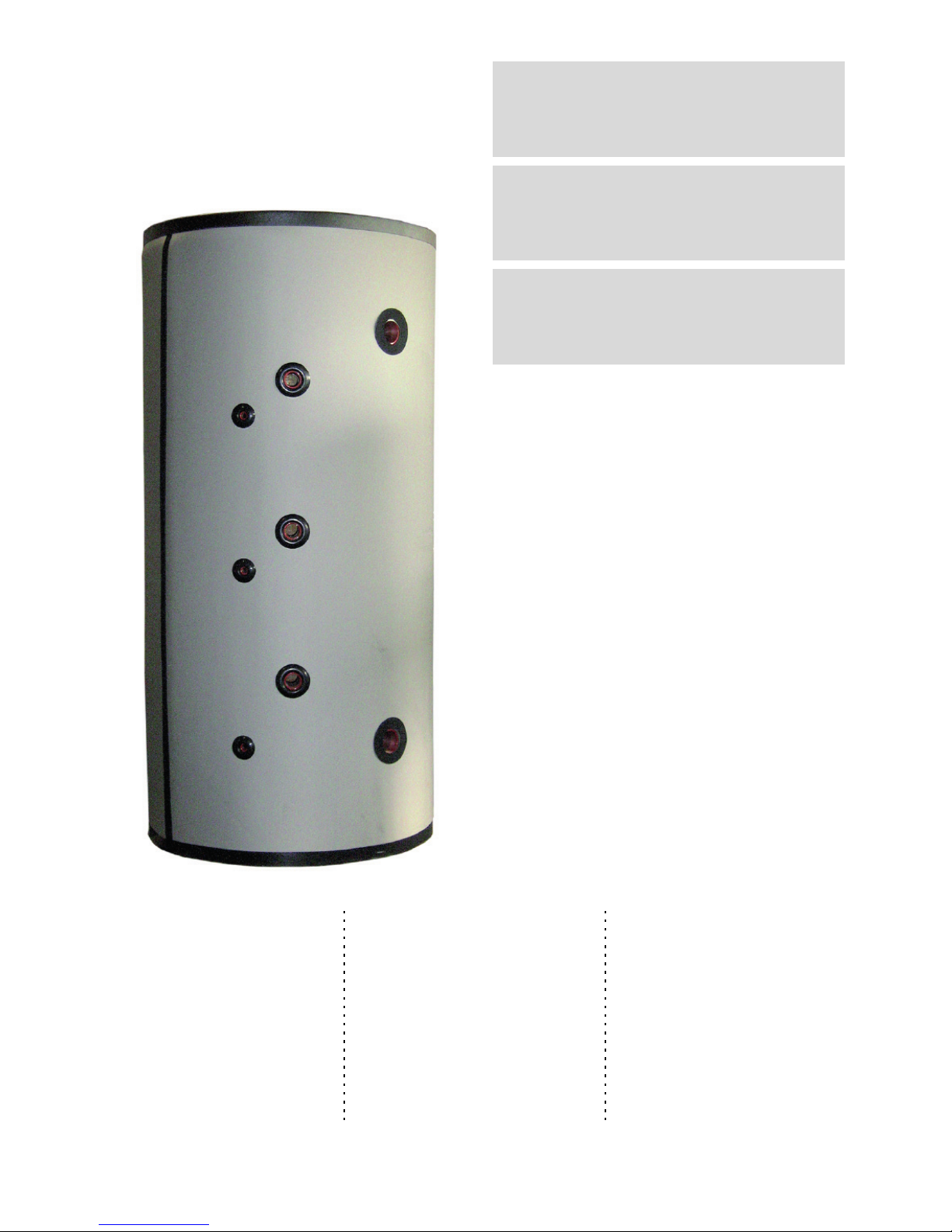
Pufferspeicher
1000 Liter zum
Heizen und
Kühlen
Buffer tank 1000
litres for heating
and cooling
Caractéristiques
techniques dimensions du
ballon tampon
PSP 1000K
Page 2

Page 3

PSP 1000K · FD 9802 DE-1
PSP 1000K Deutsch
Inhaltsverzeichnis
1 Bitte sofort lesen........................................................................................................................ DE-2
1.1 Allgemeine Hinweise ........................................................................................................................... DE-2
1.2 Bestimmungsgemäße Gebrauch ......................................................................................................... DE-2
2 Aufstellung und Installationshinweise..................................................................................... DE-3
2.1 Allgemein ............................................................................................................................................. DE-3
2.2 Sicherheitsventil................................................................................................................................... DE-3
2.3 Inbetriebnahme.................................................................................................................................... DE-3
3 Technische Daten - Abmessungen Pufferspeicher ................................................................ DE-4
4 Wartung Pufferspeicher ............................................................................................................ DE-5
5 Ersatzteile ................................................................................................................................... DE-5
Page 4

DE-2 PSP 1000K · FD 9802
Deutsch PSP 1000K
1 Bitte sofort lesen
1.1 Allgemeine Hinweise
Bitte lesen sie diese Anleitung vor der Installation des Speichers
sorgfältig durch und beachten Sie insbesondere die Sicherheitshinweise dieser Anleitung.
ACHTUNG!
!!
Für Schäden, die durch Nichtbeachtung dieser Anleitung entstehen,
übernehmen wir keine Haftung!
Bitte geben sie diese Montageanweisung und alle dem Speicherbehälter beiliegenden Unterlagen zur Aufbewahrung an den Anlagenbetreiber weiter.
Der Speicherbehälter entspricht der ErP-Richtlinie 2009/125/EG
(umweltgerechte Gestaltung) und 2010/30/EU (Energieeffizienz)
des Europäischen Parlaments.
Die delegierte Verordnung (EU) Nr. 814/2013 sowie die Verordnung (EU) Nr. 812/2013 der Kommission werden ebenfalls erfüllt.
1.2 Bestimmungsgemäße Gebrauch
Der Speicher dient ausschließlich zur Pufferung von Wasser in
geschlossenen Heizungs- und Kältekreisläufen. Er darf nur zu
diesem Zweck eingesetzt werden. Jede andere Verwendung
stellt einen Missbrauch dar und ist untersagt.
Der Pufferspeicher ist in Kombination mit Wärmepumpen zum
Heizen bzw. Heizen/Kühlen einzusetzen, auch eine Verwendung
in anderen Wasser-Heizungs- bzw. Kälteanlagen ist möglich.
Eine andere oder darüberhinausgehende Benutzung gilt als
nicht bestimmungsgemäß. Für daraus resultierende Schäden
haftet allein der Anwender.
Zur bestimmungsgemäßen Verwendung gehören ebenfalls das
Beachten der Montageanweisung und die Einhaltung der Wartungsintervalle.
HINWEIS
º
Der Pufferspeicher ist nicht emailliert und darf auf keinen Fall für die
Brauchwasser-Erwärmung verwendet werden.
Page 5
PSP 1000K · FD 9802 DE-3
PSP 1000K Deutsch
2 Aufstellung und Installationshinweise
2.1 Allgemein
Die Montage und Installation des Speichers muss durch
eine zugelassene Fachfirma erfolgen!
Die Aufstellung muss in einem frostsicheren Raum erfolgen,
die Leitungswege sind so kurz wie möglich zu halten.
Der Aufstellungsort des Speichers ist so zu wählen, dass
eine zweckmäßige Leitungsführung erfolgen kann.
Unebenheiten am Aufstellungsort sind auszugleichen da der
Speicher wegen Kippgefahr geradestehen muss.
Mittels Schrauben ist der Speicher auf der Transportpalette
befestigt. Durch Lösen der Schrauben (unter der abnehmbaren Speicherwärmedämmung) kann der Speicher zum
Aufstellort transportiert werden.
Alle nicht benötigten Anschlussmuffen müssen mit Ver-
schlussstopfen verschlossen werden.
Die auf dem Typenschild angegebenen Betriebsüberdrücke
dürfen nicht überschritten werden. Gegebenenfalls ist die
Montage eines Druckminderers erforderlich.
Elektroheizstäbe (Tauchheizkörper) dürfen nur von autori-
sierten Elektrofachkräften nach entsprechendem Schaltbild
angeschlossen werden. Die Vorschriften des EVU, VDE und
DIN 4751-2 sind zwingend einzuhalten.
HINWEIS
º
Beschädigungen an der Kältedämmung, insbesondere bei der
Installation vermeiden. Schon kleinste Beschädigungen führen zu
Kondensatausfall. Der Dämmschutz des Puffer-Speichers im Kühlbetrieb
ist dadurch nicht mehr gegeben.
HINWEIS
º
Alle Anschlüsse sind aus dem Speicher herausgeführt und bündig mit
dem Speichermantel der (abnehmbaren) Wärme-Dämmung. Die
Anschlussstutzen sind bis zum Gewinde mit einer 25 mm Kältedämmung
zur Vermeidung von Kondensat versehen. Alle für die Installation nicht
benötigten Anschlussstutzen (Vor- und Heizungsrücklauf, Tauchhülsen
und Muffen für E-Heizstäbe) müssen mit einem Blindstopfen
verschlossen und zwingend ebenfalls mit einer mind. 25 mm starken
Kältedämmung abgedichtet werden.
Alle abgehenden Rohrleitungen sind ebenfalls mit einer Kältedämmung zu versehen. Für einen optimalen Schutz vor Kondensatausfall sollten sich Rohr- und Speicherkälte-Dämmung an der
Schnittstelle überlappen.
Wird ein Anschlussstutzen nicht belegt ist er mit einem Stopfen
oder einer Kappe abzudichten.
HINWEIS
º
Die spätere Installation des Speichers muss mit aufgezogener WärmeDämmung/Verkleidung erfolgen.
HINWEIS
º
Wird die Speicher-Wärmedämmung in den kalten Monaten demontiert
muss diese vor der Montage bei Zimmertemperatur gelagert werden um
Schäden an der Dämmung und am Verschlussmechanismus zu
vermeiden!
HINWEIS
º
Am unteren Stutzen (Speicherboden) sollte eine Entleerungsvorrichtung
vorgesehen werden.
HINWEIS
º
Beigefügtes Typschild und Anschlussplan nach Aufstellung und
Montage der Dämmung sichtbar auf den Speichermantel aufkleben
2.2 Sicherheitsventil
Wird der Pufferspeicher mit einem oder mehreren Tauchheizkörpern ausgerüstet muss dieser zusätzlich mit einem baumustergeprüften, nicht absperrbaren Membran-Sicherheitsventil ausgestattet werden.
Der Anschlussdurchmesser muss mindestens Nennweite (NW)
20 betragen. Die Ausblasleitung darf keine Drucksteigerungen
ermöglichen.
Die Funktionssicherheit des Sicherheitsventils ist in regelmäßigen Abständen zu überprüfen.
2.3 Inbetriebnahme
Vor Inbetriebnahme prüfen, ob die Wasserzufuhr geöffnet und
der Speicher gefüllt ist.
Die Erstbefüllung und Inbetriebnahme muss von einer zugelassenen Fachfirma erfolgen.
Hierbei sind Funktion und Dichtigkeit der gesamten Anlage einschließlich der montierten Teile zu prüfen.
Page 6
DE-4 PSP 1000K · FD 9802
Deutsch PSP 1000K
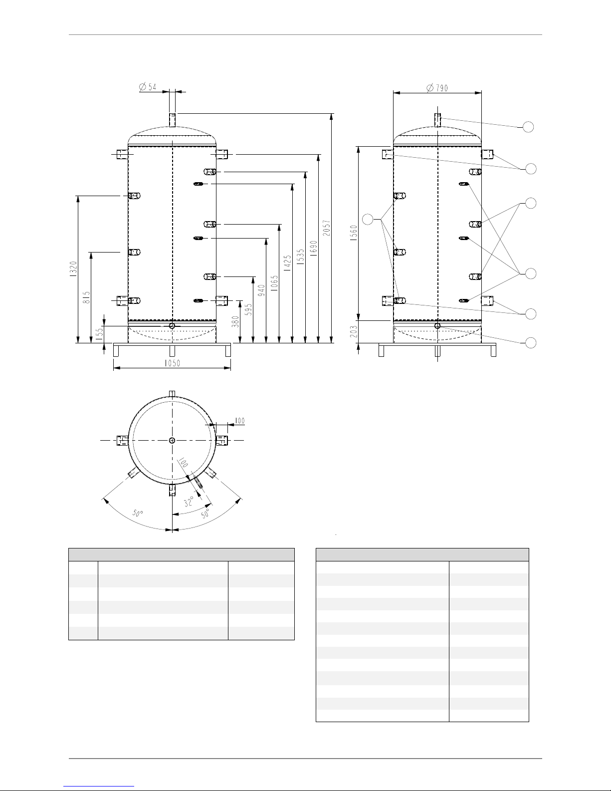
3 Technische Daten - Abmessungen Pufferspeicher
W
6
5
1
3
2
4
1
Anschlüsse
1
Heizstabeinsätze
1 ½“ IG
2
Anschluss für Entlüftung
G 1 ½“ IG
3
Anschluss für Entleerung
G 1 ½“ IG
4
Heizwasservorlauf
G 2 ½“IG
5
Heizwasserrücklauf
G 2 ½“ IG
6
Tauchhülse
Rp ½“
Technische Angaben
Nenninhalt 1000 Liter
Nutzinhalt 870 Liter
Kippmaß ohne Wärmedämmung 2035 mm
Höhe komplett 2067 mm
Durchmesser ohne Wärmedämmung 790 mm
Durchmesser mit Wärmedämmung 1000 mm
Dämmstärke Kältedämmung 25 mm
Dämmstärke Wärmedämmung 100 mm
Nettogewicht 120 kg
Wärmeverlust
1
1. Raumtemperatur 20 °C; Speichertemperatur 65 °C
3,3 kWh/24h
zul. Betriebstemperatur Heizwasser 95 °C
zul. Betriebsüberdruck Heizwasser 6 bar
Prüfdruck 9 bar
Page 7

PSP 1000K · FD 9802 DE-5
PSP 1000K Deutsch
4 Wartung Pufferspeicher
Die Voraussetzung für eine stete Betriebsbereitschaft, Zuverlässigkeit und hohe Lebensdauer ist eine regelmäßige Wartung
durch einen anerkannten Fachhandwerksbetrieb.
ACHTUNG!
!!
Niemals Wartungsarbeiten selbst durchführen. Beauftragen sie damit
einen anerkannten Fachhandwerksbetrieb.
Der Elektroeinsatz (falls vorhanden) ist jährlich, bei entspre-
chend hartem Wasser auch in kürzeren Abständen zu prüfen und ggf. zu entkalken. Hiermit ist eine Funktionskontrolle
zu verbinden.
Eine Überprüfung der Anlage wird 1x jährlich empfohlen.
HINWEIS
º
Alte oder beschädigte Dichtungen müssen ausgewechselt werden.
5 Ersatzteile
Eine Auflistung evtl. benötigter Ersatzteile ist auf unserer Webseite im Kundendienstportal hinterlegt. Weitere Informationen zu
Ersatzteilen erteilt ihnen unser Team vom Front-Office oder ihr
Kundendienstpartner.
Page 8

DE-6 PSP 1000K · FD 9802
Deutsch PSP 1000K
Page 9

PSP 1000K · FD 9802 EN-1
PSP 1000K English
Table of Contents
1 Please read immediately ........................................................................................................... EN-2
1.1 General information ............................................................................................................................. EN-2
1.2 Intended use ........................................................................................................................................ EN-2
2 Setup and installation instructions .......................................................................................... EN-3
2.1 General ................................................................................................................................................ EN-3
2.2 Safety valve ......................................................................................................................................... EN-3
2.3 Commissioning .................................................................................................................................... EN-3
3 Technical data - buffer tank dimensions ................................................................................. EN-4
4 Maintenance buffer tank............................................................................................................ EN-5
5 Spare parts ................................................................................................................................. EN-5
Page 10

EN-2 PSP 1000K · FD 9802
English PSP 1000K
1 Please read immediately
1.1 General information
Please read this manual carefully before installing the cylinder
and observe the safety notes in particular.
ATTENTION!
!
!
We do not assume any liability for damage resulting from failure to
observe this manual.
Please pass this installation manual and all documents accompanying the cylinder to the system operator for storage.
The cylinder corresponds to the ErP directive 2009/125/EC (environmentally-friendly design) and 2010/30/EU (energy efficiency) of the European Parliament.
The delegated regulation (EU) no. 814/2013 and the regulation
(EU) no. 812/2013 of the commission are also fulfilled.
1.2 Intended use
The cylinder is only used for buffering water in closed heating
and refrigerant circuits. It may only be used for this purpose. Any
other use is classed as misuse and is prohibited.
The buffer tank must be used in combination with heat pumps for
heating or heating/cooling, use in other water heating systems or
chillers is also possible.
Any other or further use is regarded as misuse. The user is solely
responsible for any resulting damage.
Intended use also includes observing the installation manual and
complying with the maintenance intervals.
NOTE
º
Buffer tanks are not enamelled and, for this reason, should never be used
for domestic water heating.
Page 11

PSP 1000K · FD 9802 EN-3
PSP 1000K English
2 Setup and installation instructions
2.1 General
The cylinder must be mounted and installed by an author-
ised specialist company!
The set-up must take place in a frost-protected room, the
cable paths must be kept as short as possible.
The installation location of the cylinder must be chosen so
that the lines can be routed sensibly.
Unevenness at the installation location must be evened out,
as the cylinder must stand level due to the risk of tipping.
The cylinder is fixed on the transport pallet with screws. The
cylinder can be transported to the installation location by
loosening the screws (below the removable thermal insulation of the cylinder).
All connecting sleeves which are not required should be
sealed with vent plugs.
The maximum permissible operating overpressure indicated
on the type plate must not be exceeded. It may be necessary to mount a pressure reducer.
Electric heating elements (immersion heaters) must only be
connected by authorised electricians according to the corresponding circuit diagram. All relevant requirements of the
utility company, the Association of German Engineers (VDE)
and DIN 4751-2 must be observed.
NOTE
º
Damage to the thermal insulation, in particular during installation, must
be avoided. Even minor damage can result in condensate fallout. This
means that the insulation protection of the buffer tank during cooling
operation is no longer effective.
NOTE
º
All connections lead out from the cylinder and are flush to the cylinder
casing of the (removable) thermal insulation. The connecting stubs are
fitted with a 25 mm thermal insulation to the thread to prevent
condensate. All connecting stubs not required for the installation (flow
and return, immersion sleeves and sleeves for electric heating elements)
must be closed with a sealing plug and sealed with thermal insulation
with a thickness of at least 25 mm.
All outgoing pipes must also be fitted with thermal insulation. To
achieve optimal protection from condensate fallout, pipe and cylinder thermal insulation should overlap on the interface.
If a connecting stub is not in use, it should be sealed using a cap
or sealing plug.
NOTE
º
The subsequent installation of the cylinder must take place with the
thermal insulation/panelling fitted.
NOTE
º
If the thermal insulation of the cylinder is removed in the cold months, it
must be stored at room temperature before installation in order to avoid
damage to the insulation and fastening mechanism.
NOTE
º
A means of draining the cylinder should be provided on the lower stub
(base of the cylinder).
NOTE
º
After the cylinder has been installed and the insulation fitted, affix the
supplied type plate and connection diagram so that they are visible on the
cylinder casing.
2.2 Safety valve
If the buffer tank is fitted with one or more immersion heaters, it
must additionally be equipped with a type-tested diaphragm
safety valve which cannot be shut off.
The connection diameter must have a nominal width (NW) of at
least 20. The air outlet pipe must not allow any pressure increase
to take place.
The operational reliability of the safety valve must be checked at
regular intervals.
2.3 Commissioning
Ensure that the water supply is turned on and the buffer tank is
filled before commissioning.
The first filling and commissioning must be performed by an authorised specialist company.
The entire system, including all installed components, should be
inspected to ensure that everything is working properly and that
there is no leakage.
Page 12

EN-4 PSP 1000K · FD 9802
English PSP 1000K
3 Technical data - buffer tank dimensions
6
5
1
3
2
4
1
Connections
1
Heating element inserts
1 ½“ internal thread
2
Connection for de-aeration
G 1 ½“ internal thread
3
Connection for drainage
G 1 ½“ internal thread
4
Heating water flow
G 2 ½“ internal thread
5
Heating water return
G 2 ½“ internal thread
6
Immersion sleeve
Rp ½“
Technical information
Nominal capacity
1000 litres
Usable capacity
870 litres
Tilt dimension without thermal insulation
2035 mm
Height complete
2067 mm
Diameter without thermal insulation
790 mm
Diameter with thermal insulation
1000 mm
Insulation thickness thermal insulation
25 mm
Insulation thickness thermal insulation
100 mm
Net weight
120 kg
Heat loss
1
1. Room temperature 20 °C; cylinder temperature 65?
3.3 kWh/24h
Permissible operating temperature, heating
water
95 °C
Permissible operating overpressure, heating water
6 bar
Test pressure
9 bar
Page 13

PSP 1000K · FD 9802 EN-5
PSP 1000K English
4 Maintenance buffer tank
A stable readiness for operation, reliability and long service life
requires regular maintenance by a recognized specialist company.
ATTENTION!
!!
Never carry out maintenance work yourself. Commission a recognized
specialist company to carry out the work.
The electrical insert (if present) should be checked and de-
scaled annually (or more frequently in hard water areas).
This should be combined with a functional test.
We recommended having the system checked once a year.
NOTE
º
Old or damaged seals must be replaced.
5 Spare parts
A list of any spare parts required can be found on our website in
the after-sales service portal. Further information on spare parts
is available from our team in the front office or your after-sales
service partner.
Page 14

EN-6 PSP 1000K · FD 9802
English PSP 1000K
Page 15

PSP 1000K · FD 9802 FR-1
PSP 1000K Français
Table des matières
1 À lire immédiatement..................................................................................................................FR-2
1.1 Remarques d’ordre général ................................................................................................................. FR-2
1.2 Utilisation conforme ............................................................................................................................. FR-2
2 Mise en place et consignes d'installation.................................................................................FR-3
2.1 Généralités .......................................................................................................................................... FR-3
2.2 Vanne de sécurité................................................................................................................................ FR-3
2.3 Mise en service.................................................................................................................................... FR-3
3 Caractéristiques techniques - dimensions du ballon tampon................................................FR-4
4 Maintenance du ballon tampon .................................................................................................FR-5
5 Pièces détachées ........................................................................................................................FR-5
Page 16

FR-2 PSP 1000K · FD 9802
Français PSP 1000K
1 À lire immédiatement
1.1 Remarques d’ordre général
Lisez soigneusement ces instructions de montage avant l'installation du ballon et respectez notamment les consignes de sécurité fournies avec elles.
ATTENTION !
!!
Nous n’assumons aucune responsabilité pour les dommages survenus
par suite du non-respect de ces instructions de montage !
Veuillez remettre ces instructions de montage et tous les documents fournis avec le ballon à l'exploitant de l'installation en vue
de leur conservation.
Le ballon est conforme à la directive ErP 2009/125/CE (écoconception) et 2010/30/UE (efficacité énergétique) du Parlement
européen.
Le règlement délégué (UE) n° 814/2013 ainsi que le règlement
(UE) n° 812/2013 de la Commission sont également respectés.
1.2 Utilisation conforme
Le ballon est exclusivement conçu pour le stockage d'eau dans
des circuits frigorifiques et de chauffage fermés. Il doit uniquement être utilisé à cette fin. Toute autre utilisation est considérée
comme non conforme et interdite.
Le ballon tampon doit être utilisé, en combinaison avec des
pompes à chaleur, pour le chauffage ou le chauffage/rafraîchissement. Une utilisation dans d'autres systèmes frigorifiques ou
de chauffage à l'eau est également possible.
Toute autre utilisation est considérée comme non conforme.
L'utilisateur est seul responsable des dommages en résultant.
L'utilisation conforme englobe également le respect des instructions de montage et des intervalles de maintenance.
REMARQUE
º
Le ballon tampon n'est pas émaillé et ne doit en aucun cas être utilisé
pour le réchauffement d’eau sanitaire.
Page 17

PSP 1000K · FD 9802 FR-3
PSP 1000K Français
2 Mise en place et consignes d'installation
2.1 Généralités
Le montage et l'installation du ballon doivent être effectués
par une entreprise spécialisée agréée !
L’installation doit être effectuée dans une pièce à l'abri du
gel. Veiller à réduire autant que possible la longueur des
conduites.
Installer le ballon à un emplacement permettant de poser les
conduites de manière adaptée.
Les inégalités de l'emplacement d'installation doivent être
compensées, le ballon devant être posé bien droit pour éviter tout risque de basculement.
Le ballon est fixé à la palette de transport au moyen de vis.
Après desserrage des vis (sous l'isolation thermique amovible du ballon), le ballon peut être transporté jusqu'au lieu
d'installation.
Tous les manchons de raccordement non utilisés doivent
être obturés avec des bouchons de fermeture.
Les surpressions de service indiquées sur la plaque signalé-
tique ne doivent pas être dépassées. Le cas échéant, le
montage d'un détendeur est nécessaire.
Seul un électricien qualifié est autorisé à raccorder les résis-
tances électriques (résistances immergées) selon le
schéma de câblage correspondant. Les prescriptions de la
société d'électricité ainsi que les prescriptions VDE et
DIN 4751-2 doivent être impérativement respectées.
REMARQUE
º
Éviter tout endommagement de l'isolation frigorifique, notamment lors de
l'installation. Les moindres dommages provoquent la formation de
condensats. La protection du ballon tampon par isolation n'est alors plus
assurée en mode rafraîchissement.
REMARQUE
º
Tous les raccords sortent du ballon et sont en affleurement avec
l'enveloppe de l'isolation thermique (amovible) du ballon. Les tubulures
de raccordement sont pourvues d'une isolation frigorifique de 25 mm
jusqu'au filet afin d'éviter les condensats. Toutes les tubulures de
raccordement qui ne sont pas nécessaires à l'installation (départ et
retour circuit de chauffage, doigts de gant et manchons pour les
résistances électriques) doivent être fermées au moyen d'un obturateur
et être aussi impérativement protégées au moyen d'une isolation
frigorifique de 25 mm d'épaisseur.
Tous les tuyaux sortants doivent eux aussi être pourvus d'une
isolation frigorifique. Pour une protection optimale contre la formation de condensats, l'isolation de tuyau et l'isolation frigorifique du ballon doivent se chevaucher au point d'intersection.
Si une tubulure de raccordement n’est pas utilisée, elle doit être
fermée avec un obturateur ou un bouchon.
REMARQUE
º
L'installation ultérieure du ballon doit être effectuée avec isolation
thermique/revêtement en place.
REMARQUE
º
En cas de démontage de l'isolation thermique du ballon durant les mois
d'hiver, celle-ci doit être conservée à température ambiante avant le
montage afin d’éviter tout endommagement de l’isolation et du
mécanisme de fermeture !
REMARQUE
º
Prévoir un dispositif de vidange sur la tubulure du bas (base du ballon).
REMARQUE
º
Apposer la plaque signalétique jointe et le schéma électrique de manière
visible sur l'enveloppe du ballon après l'installation et le montage de
l'isolation.
2.2 Vanne de sécurité
Si le ballon tampon est doté d’une ou plusieurs résistances immergées, il doit être équipé en plus d'une vanne de sécurité à
membrane homologuée ne pouvant pas être bloquée.
Prévoir un diamètre nominal (DN) d’au moins 20 pour le raccordement. La conduite d’évacuation d’air ne doit en aucun cas
rendre possible une élévation de la pression.
Contrôler à intervalles réguliers le bon fonctionnement de la
vanne de sécurité.
2.3 Mise en service
Avant la mise en service, vérifier que l’alimentation en eau est
assurée et que le ballon est rempli.
Le premier remplissage et la mise en service doivent être effectuées par une entreprise spécialisée agréée.
Lors de cette opération, contrôler le bon fonctionnement et
l’étanchéité de toute l’installation, y compris des pièces montées.
Page 18

FR-4 PSP 1000K · FD 9802
Français PSP 1000K
3 Caractéristiques techniques - dimensions du ballon
tampon
6
5
1
3
2
4
1
Raccords
1
Raccords résistance électrique
1 filet. int. ½“
2
Raccord de purge
Filet. 1 filet. int. ½“
3
Raccord de vidange
Filet. 1 filet. int. ½“
4
Départ d'eau de chauffage
Filet. 2 filet. int. ½“
5
Retour d'eau de chauffage
Filet. 2 filet. int. ½“
6
Doigt de gant
Rp ½“
Données techniques
Capacité nominale 1000 litres
Capacité utile 870 litres
Hauteur appareil basculé sans isolation
thermique
2035 mm
Hauteur complète 2067 mm
Diamètre sans isolation thermique 790 mm
Diamètre avec isolation thermique 1000 mm
Épaisseur isolation frigorifique 25 mm
Épaisseur isolation thermique 100 mm
Poids net 120 kg
Perte de chaleur
1
1. Température ambiante 20 °C ; température du ballon 65 °C
3,3kWh/24h
Température de fonctionnement admissible
eau de chauffage
95 °C
Surpression de service admissible eau de
chauffage
6 bar
Pression d'épreuve 9 bar
Page 19

PSP 1000K · FD 9802 FR-5
PSP 1000K Français
4 Maintenance du ballon tampon
Une maintenance régulière effectuée par une entreprise spécialisée homologuée est indispensable pour assurer une disponibilité constante, un fonctionnement fiable et une durée de vie élevée.
ATTENTION !
!
!
Ne procédez jamais vous-même aux opérations de maintenance. Confiezles à une entreprise spécialisée homologuée.
L’insert électrique (si installé) doit être contrôlé, et détartré si
nécessaire, une fois par an ou à des intervalles plus courts
en fonction de la dureté de l'eau. Un contrôle du fonctionnement doit également être effectué lors de cette opération.
Il est recommandé de contrôler l'installation une fois par an.
REMARQUE
º
Les joints usés ou vieux doivent être remplacés.
5 Pièces détachées
Une liste des pièces détachées éventuellement nécessaires est
disponible sur le portail du SAV de notre site web. Pour de plus
amples informations sur les pièces détachées, consultez notre
équipe du service clientèle ou votre partenaire SAV.
Page 20

Garantiebedingungen und Kundendienstadresse siehe Montage- und Gebrauchsanweisung Wärmepumpe.
For the terms of the guarantee and after-sales service addresses, please refer to the Installation and Operating Instructions for Heat Pumps.
Pour les conditions de garantie et les adresses SAV, se référer
aux instructions de montage et dútilisation de la pompe à chaleur.
Irrtümer und Änderungen vorbehalten.
Subject to alterations and errors.
Sous réserve d’erreurs et modifications.
 Loading...